Note: Descriptions are shown in the official language in which they were submitted.
CA 02769452 2016-12-23
PRESSURE RELIEF DEVICE INTEGRITY SENSOR
[001]
FIELD OF THE DISCLOSURE
[002] This disclosure
generally relates to a sensor for sensing the integrity
of a pressure relief device, along with associated systems and methods.
BACKGROUND
[003) Pressure relief devices are commonly used as safety devices in
systems containing pressurized fluids in gas or liquid form. A pressure relief
device
will vent fluid from a system when the pressure in the system reaches a
predetermined level¨usually before it reaches an unsafe level. Exemplary
pressure relief devices include explosion vents and rupture disks. Examples of
pressure relief devices include those illustrated in co-owned U.S. Patent
Nos. 4,441,350 and 4,481,850.
[004] Pressure relief devices may come in any number of materials and
shapes. Pressure relief devices are commonly manufactured from metal; however,
they may be made from polycarbonate sheeting, woven fabric, elastomers, or a
combination of materials. A pressure relief device may be rectangular, round,
trapezoidal, triangular, or any custom shape desired to fit a given
application.
[005) A pressure relief device may be provided with at least one designed
area of weakness, which controls the set pressure and/or at least one location
at
which the device will vent fluid from the system. A designed area of weakness
may
be manufactured directly into the material of the pressure relief device. For
example, a burst pattern or opening pattern may be cut by laser, mechanical
- 1 -
CA 02769452 2016-12-23
cutting, water jet cutting, or any other suitable method for cutting the
pressure relief
device. When cut into a burst pattern or opening pattern, the pressure relief
device
may concentrate pressure on uncut areas between cuts. These areas may
constitute
the designed areas of weakness. In another example, a designed area of
weakness
may be formed by way of a score line, shear line, indentation, or any other
suitable
manufacturing process that weakens part of the pressure relief device.
[006] A designed area of weakness also may comprise a secondary
component added to the pressure relief device. For example, when a pressure
relief
device is cut into a desired opening pattern, it may be provided with at least
one
activation component affixed to the pressure relief device. The activation
component
may take the form of a tab or any other component suitable to control the
pressure at
which a pressure relief device opens. The activation component may be made
from a
number of suitable materials. For example, it may be desired to provide a
light weight
plastic, such as polycarbonate, pressure relief device with at least one metal
activation component. Such a pressure relief device will vent fluid when the
pressure
on the device causes the metal activation component(s) to fail.
[007] The designed areas of weakness may also be designed for the pressure
relief device to burst or rupture in a particular pattern. A pressure relief
device may be
designed to burst or rupture peripherally, such that a single "petal" of the
explosion
vent opens to release fluid. For example, a rectangular pressure relief device
may be
cut or weakened on three sides, leaving the fourth side to act as a hinge to
retain the
device's petal when fluid is released. Alternatively, a pressure relief device
may be
designed to burst or rupture centrally. For example, a rectangular pressure
relief
device may be cut or weakened along a diagonal line and a circular pressure
relief
device may be cut or weakened along a radial line.
[008] Pressure relief devices may be provided with activation sensors to
detect
when a pressure relief device is opened or activated, e.g., in response to an
overpressure situation. Such activation sensors are disclosed in commonly
owned
U.S. Patent Nos. 4,978,947 and 6,598,454. An activation sensor may be a
magnetically activated proximity switch. Alternatively, an activation sensor
may be a
-
CA 02769452 2016-12-23
loop of wire that breaks when the pressure relief device opens. Such
activation
sensors may be
- 2a -
CA 02769452 2012-01-27
WO 2011/014798
PCT/US2010/043958
used to trigger an automated process shut down upon activation of the pressure
relief device.
[009] A pressure relief device may become strained or compromised
without activation. Sources of strain on a pressure relief device may include
damage due to external factors such as wind, lightning, or impact by a foreign
object. Another source of strain on a pressure relief device may be pressure
from
the system. For example, a pressure relief device may experience subtle
changes
in its physical profile as the pressures applied to it¨including forward and
back
pressures¨change. A pressure relief device may have a particular region or
feature that is particularly responsive to such changes prior to activation of
the
pressure relief device. That region may occur at or adjacent to a designed
area of
weakness. Alternatively, that region may occur at a point that is apart from
the
designed area of weakness but nonetheless experiences a relatively high level
of
pre-activation deformation in response to pressure changes. As one example, in
a
pressure relief device having a cross-shaped score line pattern that divides
the
pressure relief device into four "petals," a particularly responsive region
may be
located near the center of each petal. Whether located at a designed area of
weakness or elsewhere, a particularly responsive region may be referred to as
a
pre-activation reactive region.
[010] If a pressure relief device is strained or compromised without
activating, the compromised condition may go undetected by an activation
sensor.
In addition, a strained or compromised pressure relief device may not be
detected
by visual inspection. Many pressure relief devices are used in remote,
concealed,
or elevated areas that make visual inspection difficult. Additionally, many
pressure
relief devices are used in negative pressure systems that would prevent gases
or
liquids from visibly leaking out of a damaged pressure relief device. Such
systems
may make the telltale signs of process leakage unavailable or unreliable as a
means of identifying the compromised condition of the pressure relief device.
[011] An undetected leak can be dangerous or otherwise undesirable,
because it may vent gas or liquid from the system into the environment.
Additionally, an undetected leak may expose the system to undesirable elements
from the environment, such as moisture, gas, or dust ingress from the
surrounding
environment. An undetected strain on the pressure relief device may adversely
- 3 -
affect the performance of the pressure relief device, including its longevity
or the
pressure at which it will activate.
[012] In light of the foregoing, there is a need for a pressure relief device
integrity sensor that can detect an abnormal mode of a pressure relief device-
i.e.,
when a pressure relief device has become compromised or strained without
activating, or when activation of a pressure relief device is imminent but has
not yet
occurred. Thereby, an operator may know to replace a compromised or strained
pressure relief device before secondary complications or dangers occur. The
integrity
sensor-and associated systems and methods-of the present disclosure achieves
these, or other, advantages.
SUMMARY
[013] According to one embodiment, there is provided a pressure relief device
integrity sensor, comprising: a sensor element configured to sense a condition
of a
pre-activation reactive region of a rupturable pressure relief device
configured to
activate by rupturing in response to a predetermined pressure, the sensor
element
configured to transmit a signal indicating that the explosion panel is in
normal
operating condition; wherein the sensor element comprises a conductive element
exhibiting a first resistance; wherein the conductive element is configured to
deform
in response to a compromise in the integrity of the pre-activation reactive
region, and
wherein the deformation of the conductive element causes the conductive
element to
exhibit a second resistance; and wherein a change in or interruption of the
signal
indicates a compromise in the integrity of the pre-activation reactive region
before
activation of the pressure relief device.
[014] According to another embodiment, there is provided a system for
sensing the integrity of a pressure relief device, comprising: a non-
reversible
pressure relief device having one or more pre-activation reactive regions; and
at least
one sensor element configured to transmit a signal indicating a condition of
at least
one of the one or more pre-activation reactive regions before the pressure
relief
- 4 -
CA 2769452 2019-07-08
device activates, wherein the sensor element comprises a conductive element
exhibiting a first resistance; wherein the conductive element is configured to
deform
when the integrity of the one or more pre-activation reactive regions is
compromised
before activation of the pressure relief device, wherein the deformation of
the
conductive element cause the conductive element to exhibit a second
resistance.
[015] According to another embodiment, there is provided a method of
monitoring a non-reclosable pressure relief device, comprising: sensing a
condition
of a pre-activation reactive region of the pressure relief device;
transmitting a first
signal indicative of a condition of the pressure relief device, wherein the
signal
comprises an electrical signal having a voltage and a current; and changing or
interrupting at least one of the voltage and current of the electrical signal
to indicate
that the pre-activation reactive region of the pressure relief device has
deformed
without rupturing.
[016] According to another embodiment, there is provided a pressure relief
apparatus for a pressurized system comprising: a pressure relief device
comprising
an activating portion configured to relieve pressure by bursting or rupturing
when
pressure in the pressurized system exceeds a threshold, wherein the activating
portion comprises a designed area of weakness and a pre-activation reactive
region;
and an integrity sensor configured to sense that the pressure relief device
has
weakened before activation, the sensor comprising a conductive element
exhibiting
a first resistance, wherein the conductive element is configured to deform and
exhibit
a second resistance when the pressure relief device has weakened before
activation.
[017] According to another embodiment, there is provided a method of
monitoring the integrity of a non-reclosing pressure relief device having a
pre-
activation reactive region, wherein the pressure relief device is installed
with a
pressurized system, comprising: sensing a strain at the pre-activation
reactive region,
wherein sensing a strain comprises deforming a conductive element to change
the
resistance of the conductive element; and generating a signal when the strain
indicates that the pressure relief device has been deformed without activating
- 5 -
CA 2769452 2019-07-08
[018] According to another embodiment, there is provided a method of
monitoring the integrity of a rupturable pressure relief device configured to
activate by
rupturing in response to an overpressure, comprising: applying a pressure to
the
rupturable pressure relief device; measuring a strain of at least one region
of the
rupturable pressure relief device; identifying a pre-activation reactive
region based on
the strain measured at the at least one region of the rupturable pressure
relief device;
and monitoring a deformation of the pre-activation reactive region prior to
activation
of the rupturable pressure relief device; wherein monitoring a deformation of
the pre-
activation reactive region before activation of the pressure relief device
comprises
deforming a conductive element in response to the deformation, wherein
deforming
the conductive element cause a change in the resistance of the conductive
element.
[019]
BRIEF DESCRIPTION OF THE DRAWINGS
[020] The accompanying drawings, which are incorporated in and constitute a
part of this specification, illustrate several embodiments and together with
the
description, serve to explain principles of the disclosure.
[021 ] FIG. 1 is a diagrammatic illustration of an integrity sensor installed
with
a pressure relief device according to one aspect of the disclosure;
[022] FIG. 2 is a diagrammatic illustration of an integrity sensor including a
sensing device installed with a pressure relief device according to one aspect
of the
disclosure;
[023] FIG. 3A is a diagrammatic illustration of an integrity sensor installed
with
an explosion vent;
[024] FIG. 3B is an exploded cross-sectional illustration of the integrity
sensor
of FIG. 3A along line A-A;
- 5a -
CA 2769452 2019-07-08
CA 02769452 2012-01-27
WO 2011/014798
PCT/US2010/043958
[025] FIG. 4A is a diagrammatic illustration of a fracture member with a
conductive path positioned across a designed area of weakness;
[026] FIG. 4B is a cross-sectional illustration of the fracture member of
FIG. 4A along line B-B;
[027] FIG. 5A is a diagrammatic illustration of a strain gage for use in an
integrity sensor;
[028] FIG. 5B is a diagrammatic illustration of an integrity sensor comprising
a plurality of strain gages ;
[029] FIG. 6 is a cross-sectional illustration of an integrity sensor
installed
with a forward-acting rupture disk;
[030] FIG. 7 is a cross-sectional illustration of an integrity sensor
installed
with a reverse-acting rupture disk;
[031] FIG. 8 is a diagrammatic illustration of a strain gage for use in an
integrity sensor, installed across a score line;
[032] FIG. 9 is a diagrammatic illustration of an integrity sensor installed
with a cutting tab;
[033] FIG. 10 is a diagrammatic illustration of integrity sensors installed on
a rupture disk;
[034] FIG. 11A is a diagrammatic illustration of a rupture disk with an
indentation and a score line coupled with an integrity sensor;
[035] FIG. 11B is a perspective view of the rupture disk of FIG. 11A after
activation; and
[036] FIGS. 12A-12C illustrate various sensors.
DESCRIPTION OF THE EMBODIMENTS
[037] Reference will now be made in detail to the present exemplary
embodiments, examples of which are illustrated in the accompanying drawings.
[038] An exemplary embodiment of an integrity sensor of the present
disclosure is shown in FIG. 1. In accordance with the disclosure, there is
provided
a sensor element 5 that connects via a pathway¨sensor loop 10¨to a monitor 20
that monitors a signal of the sensor element 5. Sensor element 5 may be a
segment of sensor loop 10 configured to transmit a signal, or sensor element 5
may
be a separate component from sensor loop 10 configured to transmit a signal.
By
- 6 -
CA 02769452 2012-01-27
WO 2011/014798
PCT/US2010/043958
"transmitting" the signal, the sensor element 5 may, for example, originate or
generate a signal, pass a signal originated or generated elsewhere within a
sensor
loop 10, or modify a signal originated or generated elsewhere within a sensor
loop
10.
[039] As shown in FIG. 1, the pathway in the form of sensor loop 10 is
physically connected to the monitor 20; however, one of skill in the art would
understand that all or part of the pathway forming sensor loop 10 may be
wireless.
Thus the monitor 20 may wirelessly monitor the sensor element 5.
[040] Sensor element 5 is positioned along a pressure relief device 30
containing a pre-activation reactive region 32. Pressure relief device 30 may
be, for
example, an explosion vent or rupture disk. Pressure relief device 30 may be
installed with a pressurized system and may be designed to activate¨e.g.,
open,
burst, or rupture¨in response to a predetermined pressure within the
pressurized
system. By activating, the pressure relief device 30 allows pressure to escape
from
the pressurized system. In one embodiment, the pressure relief device 30 may
activate or initiate activation at the pre-activation reactive region 32.
[041] In some instances, the pre-activation reactive region 32 may
become strained or compromised without activating. In those instances, the pre-
activation reactive region 32 may undergo a physical change or deformation,
such
as, for example, stretching or compression. This physical change may be
different
from the change normally experienced by a pre-activation reactive region 32
during
activation, and may indicate that the pressure relief device 30 and/or pre-
activation
reactive region 32 is abnormal or damaged. Alternatively, this physical change
may
be similar to the change undergone by a pre-activation reactive region 32
during
the activation process, except the activation¨e.g., opening, bursting, or
rupturing¨
has not been completed. Physical changes or deformations that do not
immediately result in complete activation may be referred to generally as "non-
activating" changes Similarly, the physical condition of a pressure relief
device that
has not completely activated may be referred to generally as a "pre-
activation"
condition. Monitoring such non-activating changes and/or pre-activation
conditions
allows monitoring the integrity of a pressure relief device. A pressure relief
device
30 with a deformed pre-activation reactive region 32 may have lost integrity,
may
operate abnormally or unpredictably, and may require replacement.
Additionally, a
deformed pre-activation reactive region 32 may indicate that activation of the
- 7 -
CA 02769452 2012-01-27
WO 2011/014798
PCT/US2010/043958
pressure relief device is imminent. Thus by monitoring non-activating changes
and/or pre-activation conditions, an operator may replace the pressure relief
device
30 before full activation occurs.
[042] To determine whether a non-activating change evidences damage to
a pressure relief device, one may first determine the expected strain or
deformation
at the pressure relief device's maximum allowable working pressure (or at a
pressure slightly above that maximum level). In an operational pressure relief
device, if the magnitude of strain or deformation exceeds that expected level,
then
the pressure relief device may have been (or is being) compromised.
[043] In addition to magnitude of strain or deformation, other measures
may indicate that a pressure relief device has suffered (or is suffering) an
integrity-
compromising non-activating change. For example, the rate of strain on a
pressure
relief device may be used. In one embodiment, the rate of strain may be
calculated
as strain per unit of pressure. In another embodiment, the rate of strain may
be
calculated as strain per unit of time. In either embodiment, if the rate of
strain
exceeds maximum allowable levels, then the pressure relief device may have
undergone (or be undergoing) an integrity-compromising deformation. In
addition
or alternatively, the strain rate may be compared to the magnitude of pressure
acting on the device. In that case, if the strain rate exceeds a maximum
allowable
rate at a given pressure, the pressure relief device may have undergone (or is
undergoing) an integrity-compromising deformation. In one example, if strain
continues to increase when pressure is held constant, then the pressure relief
device may be compromised. To prevent false alarms, a rate-of-strain value may
be compared to the magnitude of strain. In this manner, a relatively high rate-
of-
strain value may be disregarded when the actual strain value is within safe
levels.
[044] Returning to FIG. 1, at least a portion of the sensor element 5
and/or
sensor loop 10 is attached to or made integral with the pressure relief device
30 by
way of an attachment 34 such as an adhesive, rivet, spot weld, or any other
suitable means of attachment. The sensor element 5 and sensor loop 10 may be
designed to minimize or eliminate their effect on the strength of the pressure
relief
device 30. However, alternatively, the sensor element 5 and/or sensor loop 10
may
be designed to impart additional strength to the pressure relief device 30,
such that
it will withstand a higher level of pressure.
- 8 -
CA 02769452 2012-01-27
WO 2011/014798
PCT/US2010/043958
[045] In one embodiment, the sensor element 5 and sensor loop 10 may
be made of a suitable conductive material capable of carrying or transmitting
an
energy signal. In addition, the sensor element 5 and sensor loop 10 may be
made
of a plurality of conductive materials, each of which being capable of
carrying or
transmitting an electric signal. Thus, expensive materials, such as tantalum
or
silver, may be used sparingly within the sensor 5 and sensor loop 10, if at
all. In
one embodiment, an expensive material, such as tantalum or silver, may be used
to
form the sensor element 5 while a less expensive material, such as insulated
copper wire, may be used to form the sensor loop 10. Thus tantalum or silver,
which may be desirable for their corrosion resistance, tensile strength, and
other
physical properties, may be used only where such materials can be of most use¨
e.g., adjacent a predetermined area of weakness, or where exposed to corrosive
environments. Insulated copper wire or other less expensive materials can be
used
where the particular properties of tantalum or silver, e.g., are not required.
[046] In one embodiment the sensor element 5 may comprise a
conductive wire 412 attached to a frangible fracture member 414 as best shown
in
FIGS. 4A and 4B, with the fracture member 414 being placed adjacent to a
designed area of weakness 432, which may also be a pre-activation reactive
region. The fracture member 414 may be made of plastic¨such as a thin plastic
foil, skin, or sheet¨and include a conductive track such as a printed circuit
or a
layer of wire or flattened wire. As shown in FIG. 4B, the fracture member 414
may
be arched to provide a degree of freedom of movement for a pressure relief
device.
The fracture member 414 may be designed to fracture when the designed area of
weakness 432 is deformed or compromised before activation of the pressure
relief
device.
[047] When attached or integral to the pressure relief device 30, the
sensor 5 and sensor loop 10 may be electrically isolated from the material of
pressure relief device 30 in order to prevent contamination or dissipation of
a
sensor signal running through the sensor 5 and sensor loop 10. In addition,
the
sensor 5 and sensor loop 10 may be electrically isolated from the pressure
relief
device 30 to prevent the ignition of dust or gas in or around the pressure
relief
device 30. The sensor 5 and sensor loop 10 may be electrically isolated by,
for
example, insulating tape (such as DuPontTM Kapton polyimide tape) or by use
of
an insulated wire for at least part of the sensor 5 and/or sensor loop 10.
- 9 -
CA 02769452 2012-01-27
WO 2011/014798
PCT/US2010/043958
[048] Additionally or alternatively, isolation may not be necessary where
electrical current is not present or is "safe." For example, the sensor loop
10 and
sensor element 5 may comprise a fiber optic monitoring circuit in which no
electrical
current is present, or the sensor loop 10 and sensor element 5 may comprise an
intrinsically safe electrical circuit (such as a zener circuit). Such a
circuit would
allow operation in hazardous environments, such as National Electrical Code
(NEC)
Class 1 Divisions 1 or 2 and Class 2 Divisions 1 or 2 environments and
European
ATEX Zone 0 or lower and Zone 20 or lower locations. For added safety, the
sensor loop 10 and/or sensor element 5 may be electrically grounded.
[049] In another embodiment, the sensor loop 10 may be a pneumatic
loop, which does not necessarily use an electrical signal. In this embodiment,
the
sensor loop 10 may comprise, for example, a small diameter hollow tube, and
the
sensor element 5 may comprise a segment of the small diameter hollow tube. The
sensor loop 10 is a closed loop and air flow through the tube constitutes a
normal
condition of the closed circuit. A monitoring device may monitor the air flow
with,
for example, a spinning wheel or other device for detecting air flow. When
sensor
loop 10 in the form of a tube is cut or broken at sensor element 5 in response
to a
change in the pressure relief device 30, the circuit is broken and air flow
through
the pneumatic loop will cease. Cessation of air flow may signal to the monitor
20
that the pressure relief device 30 has been compromised without activating or
is
about to activate.
[050] In yet another embodiment, the sensor loop 10 may be a
pressurized pneumatic loop whose pressure is monitored by a monitor 20. The
sensor element 5 may comprise part of the pressurized pneumatic loop. If the
pneumatic loop is broken at sensor element 5, the pressure will drop.
Alternatively,
a change in shape of the tube at sensor element 5 may cause a change in
pressure. For example, if the tube is crimped at sensor element 5, pressure
may
increase. A change in pressure of the sensor loop 10 in the form of a
pneumatic
loop may signal to the monitor 20 that the pressure relief device 30 has been
compromised without activating or that activation is imminent. Thus, an
operator
may know to replace the pressure relief device 30 before activation or before
secondary complications from a compromised pressure relief device occur.
[051] Returning to FIG. 1, the sensor loop 10 may physically connect to a
monitor 20, which may transmit and/or receive signals through the sensor loop
10.
- 10-
CA 02769452 2012-01-27
WO 2011/014798
PCT/US2010/043958
Because the integrity sensor of the present disclosure may be used in
hazardous
operating environments, the sensor loop 10 may connect to the monitor 20
through
a durable and weather resistant connector. Appropriate monitors may include
those sold by BS&B Safety Systems under the names Burst Disk Monitor (BDM),
SmartDisk wireless monitoring system, and Rupture Disk Manager. Additionally,
any monitor that may monitor, transmit, and/or receive signals transferred
through
the sensor loop 10 may be used. If a wireless monitor is used, it may monitor
a
signal transferred through the sensor loop 10 without requiring a physical
connection to the sensor loop 10.
[052] In operation, a pressure relief device 30 is installed in a first,
uncompromised state. A sensor element 5 and/or sensor loop 10 may be attached
across or attached directly to a pre-activation reactive region 32 of the
pressure
relief device 30. With the pressure relief device 30 in its uncompromised
state, the
sensor loop 10 forms a circuit with sensor element 5, allowing the monitor 20
to
continuously monitor a signal¨such as a trickle current¨in the sensor loop 10.
When the pressure relief device 30 is compromised or strained without
activating,
such as, for example, by deformation in a pre-activation reactive region 32,
it may
undergo a physical change that can be registered by the sensor 5. Sensor 5 may
transmit a signal to or through sensor loop 10.
[053] In one embodiment, the sensor loop 10 initially forms a normally
closed circuit. This circuit may be, for example, an electrical circuit,
optical circuit,
or pneumatic circuit. When the pressure relief device 30 is compromised or
strained without activating, the sensor loop 10 may be broken at sensor
element 5,
creating an open circuit. The monitor 20 may interpret the opening of the
circuit to
mean that the pressure relief device 30 has been compromised or that
activation is
imminent.
[054] In another embodiment, the sensor loop 10 initially forms a closed
electrical circuit with sensor 5, the closed circuit having a first
resistance. When the
pressure relief device 30 is compromised or strained near pre-activation
reactive
region 32, the sensor element 5 may be stretched or deformed, thereby altering
its
resistance and the resistance of the electrical circuit. For example, if
sensor
element 5 is stretched, its diameter may decrease, which increases its
resistance.
The monitor 20 may interpret a change in the electrical circuit's resistance
to mean
that the pressure relief device 30 has been compromised without activating or
that
-11-
CA 02769452 2012-01-27
WO 2011/014798
PCT/US2010/043958
activation is imminent. In a related embodiment, if the pressure relief device
30
subsequently is further compromised or activates, the sensor element 5 may
break
completely and open the initially closed electrical circuit. The monitor 20
may
interpret the circuit's opening to mean that the pressure relief device 30 has
been
further compromised or has activated. Thus, the sensor loop 10 and sensor 5
may
be able to detect both that the pressure relief device 30 has been compromised
without activating and that the pressure relief device 30 has been activated.
[055] As shown in FIG. 1, the monitor 20 may be connected to an alarm
40 or any other indicator that can notify an operator that the pressure relief
device
30 has been compromised without activating or that activation is imminent. The
alarm 40 may provide notification in the form of a light or sound.
Additionally, the
monitor 20 may be operatively connected to a computer that may register
signals
generated by the monitor 20. The computer may, in turn, have a graphical user
interface or other display that can notify an operator if the pressure relief
device 30
has been compromised without activating or that activation is imminent. The
alarm
40 and/or monitor 20 may be configured to notify an operator of a compromised
pressure relief device based, for example, on magnitude of strain or
deformation,
rate of strain, magnitude of pressure, or a combination of such factors as
discussed
above.
[056] In another embodiment, shown in FIG. 2, a sensing device 250 may
be placed adjacent to a pre-activation reactive region 232 of a pressure
relief
device 230. The sensing device 250 may be attached to pressure relief device
230
and/or the pre-activation reactive region 232 by an attachment mechanism 234.
As
illustrated in FIG. 2, the sensing device 250 physically connects to a sensor
loop
210, which physically connects to a monitor 220. It is comprehended, however,
that the sensing device 250 may be wirelessly monitored by the monitor 220. In
a
wireless embodiment, the sensor loop 210 is understood to be a non-physical
loop
by which the monitor 220 monitors a signal from the sensing device 250.
[057] When the pressure relief device 230 is in a first, uncompromised
state, the sensing device 250 may transmit a first signal to a monitor 220.
When
the pressure relief device 230 deforms at the pre-activation reactive region
232, the
sensing device 250 may transmit a second signal, different from the first
signal, to
the monitor 220, thereby signaling that the pressure relief device 230 has
been
compromised without activating or is about to activate. An appropriate sensing
- 12-
CA 02769452 2012-01-27
WO 2011/014798
PCT/US2010/043958
device 250 may include, for example, one or more strain gages (as illustrated
in
FIGS. 5A and 5B).
[058] Although the integrity sensor has been described as monitoring the
integrity of a single pre-activation reactive region, the present disclosure
also
comprehends an integrity sensor that monitors a plurality of pre-activation
reactive
regions. In the embodiment illustrated in FIGS. 3A-3B, for example, an
integrity
sensor is installed with an explosion vent 330 having a plurality of pre-
activation
reactive regions in the form of designed areas of weakness 332, which are
provided between a series of cuts 336 in a pattern. Pressure on the explosion
vent
will be concentrated in the areas between each cut 336, thus creating the
areas of
weakness 332. The cuts 336 may be created by the use of laser cut stitches or
any
other suitable methods. As shown in FIG. 3A, a sensor loop 310 is attached to
the
vent 330. A sensor element 305 extends across each of the designed areas of
weakness 332, and one or more sensor elements 305 may be attached to one or
more of the areas of weakness 332. Although FIG. 3A depicts an explosion vent
330, the disclosure may be used with any suitable pressure relief device. By
way of
non-limiting example, the disclosure may be used with a rupture disk. As
another
non-limiting example, the disclosure may be used with a composite rupture
disk,
which may include a plurality of precut designed areas of weakness.
[059] As best illustrated in FIG. 3B, the sensor loop 310 may be held next
to the explosion vent 330 by or under a gasket 338. Also as shown in FIG. 3B,
the
sensor loop 310 may be sufficiently durable to allow it to be clamped between
a
frame 360. The frame 360 may be, for example, a set of pipe flanges or part of
an
opening of a pressurized system. If the sensor loop 310 is clamped between
frame
360 or otherwise installed into a system, its initial properties may change.
For
example, if the sensor loop 310 comprises an electrical circuit, the initial
resistance
of the circuit may be affected when the sensor loop 310 is clamped between the
frame 360. In another example, if the sensor loop 310 comprises a pneumatic
circuit, the air flow or pressure of the circuit may be affected when the
sensor loop
310 is clamped between the frame 360. In either case, it may be desirable to
recalibrate a monitor 320 after the sensor loop 310 is installed to accurately
recognize when the pressure relief device 330 is compromised without
activating or
that activation is imminent.
- 13-
CA 02769452 2012-01-27
WO 2011/014798
PCT/US2010/043958
[060] As shown in FIG. 3B, the sensor loop 310 is installed external to the
pressurized system (designated as "P"). The present disclosure comprehends,
however, that one or more components of the sensor loop 310 or sensor element
305 may be installed internal to the pressurized system P.
[061] When one or more of the designed areas of weakness 332 of vent
330 deforms without activation, sensor element 305 may be broken (opening a
normally closed circuit) or stretched (increasing the resistance in the
circuit),
thereby signaling that the explosion vent 330 has been compromised. To
facilitate
breaking the sensor element 305 upon deformation of a designed area of
weakness, the sensor element(s) 305 may include one or more frangible fracture
members 414 placed adjacent to a designed area of weakness 332. As previously
described and illustrated at FIGS. 4A and 4B, a fracture member 414 may be
made
of plastic¨such as a thin plastic foil, skin, or sheet¨and include a
conductive track
such as a printed circuit or a layer of wire or flattened wire. As shown in
FIG. 4B,
the fracture member 414 may be arched to provide a degree of freedom of
movement for vent 330.
[062] An integrity sensor may be designed to stretch in response to strain
on the pressure relief device. In such a design, the integrity sensor may be
provided with one or more sensing devices in the form of a strain gage 552.
These
strain gages 552 may be positioned across a pre-activation region in the form
of a
designed area of weakness 532 as illustrated in FIGS. 5A and 5B, and may be
attached to the designed area of weakness. When a pressure relief device 530
is
in a first, uncompromised configuration, the strain gage 552 exhibits a first
resistance. Accordingly, a signal passing through the sensor loop 510 and
strain
gage 552 will have a first current as monitored by a monitor 520. When the
pressure relief device 530 is compromised or about to activate, the strain
gage 552
will be strained and exhibit a second resistance different from the first
resistance.
Thus, the signal passing through the sensor loop 510 will change. For example,
the signal may change from a first current to a second current different from
the
first. Alternatively, the signal may change from a first voltage to a second
voltage
different from the first. The signal may be monitored by a monitor 520 (as
shown in
FIG. 5B). If the second current or voltage exceeds or drops below a threshold
value, the monitor 520 may interpret the change as a signal that the pressure
relief
device 530 has been compromised without activating or is about to activate.
Where
- 14-
CA 02769452 2012-01-27
WO 2011/014798
PCT/US2010/043958
a strain gage 552 comprises part of the sensor loop 510, the sensor loop 510
may
comprise, for example, a 4-20 mA, 0-5 VDC, or 0-10 VDC circuit, or any other
suitable monitoring circuit.
[063] When a strain gage 552 is used with the present disclosure, it may
be placed into a "bridge circuit" (not shown), such that when the strain gage
552
stretches or compresses (in unison with the surface of the pressure relief
device),
the voltage across the bridge circuit changes. The voltage change across the
bridge circuit may be slight; therefore, an amplifier (not shown) may be
placed in
the circuit to boost the signal to more measurable levels. In one embodiment,
the
signal may be monitored or tracked, for example, by software or an
oscilloscope.
The bridge circuit may be mounted in an electrical enclosure external to the
pressure relief device, with only the strain gage 552 being exposed to the
pressure
relief device.
[064] In one embodiment, the strain gage 552 may be selected for its
compatibility with the material of the pressure relief device to which it is
attached.
Temperature may affect the behavior and/or shape of both the strain gage and
the
pressure relief device. Accordingly, in one embodiment, the material of a
strain
gage may be selected to match the material of the pressure relief device.
[065] In another embodiment, the strain gage 552 may be mounted in an
electrically insulating material (not shown). A pressure relief device may be
electrically conductive. For this reason, mounting the strain gage 552 in
electrically
insulating material, or otherwise electrically isolating the material from the
pressure
relief device, may prevent the signal through the strain gage from running to
ground
or dissipating through the pressure relief device.
[066] In yet another embodiment, the strain gage 552 may be rigidly
bonded to the pressure relief device. By rigidly bonding to the pressure
relief
device, the strain gage 552 may move in unison with the pressure relief
device.
[067] The strain gage 552 of the present disclosure may be applied to the
outlet side of the pressure relief device. The outlet side of a pressure
relief device
may be more benign than the inlet side. For example, the inlet side of a
pressure
relief device may be subject to corrosive or abrasive conditions. Therefore,
placing
the strain gage 552 on the outlet side of the pressure relief device may
isolate it
from such conditions. It is contemplated, however, that the strain gage 552
may be
positioned on the inlet side of a pressure relief device. In such an
application, the
-15-
CA 02769452 2012-01-27
WO 2011/014798
PCT/US2010/043958
strain gage 552 may be protected from adverse conditions. For example, the
strain
gage 552 may be protected by way of a protective barrier against harmful
electrical,
mechanical, or chemical elements. Moreover, it is contemplated that two strain
gages 552 may be used¨one each on opposing inlet and outlet sides of a
pressure relief device. In such an arrangement, both strain gages 552 may be
placed into a bridge circuit (with one being inverted). By this arrangement,
the
signal generated at a given pressure could be maximized.
[068] In yet another embodiment, the strain gage 552 may utilize a low
voltage and/or low current. Such a low voltage or low current may be capable
of
operating at intrinsically safe power levels, enabling the strain gage to be
applied in
a hazardous combustible gas or vapor or dust environment. For example, such a
strain gage 552 may be placed safely into a combustible gas or vapor media
piping
system.
[069] While an individual strain gage is illustrated in FIG. 5A, a
plurality of
strain gages 552 may be provided in series, in a "daisy chain" configuration
(or any
other suitable configuration) within the sensor loop 510 as illustrated in
FIG. 5B.
The sensor loop 510 may be installed with an explosion vent 530, for example,
in
association with a gasket 538. The explosion vent may have a series of cuts
536,
which create pre-activation reactive regions in the form of designed areas of
weakness 532. Each strain gage 552 may be attached to a designed area of
weakness 532. Based on the initial resistance of each strain gage, the "daisy
chain" sensor loop 510 will have an initial resistance value. When one or more
designed areas of weakness 532 is strained, the resistance of its associated
strain
gage 552 will change. Likewise the resistance in the sensor loop 510 will
change in
a manner that may indicate the integrity of the pressure relief device 530 has
been
compromised without activating or that activation is imminent.
[070] An integrity sensor including a strain gage 552, as illustrated in
FIGS. 5A and 5B, may also be useful for a pressure relief device in the form
of a
rupture disk 630 or 730 (illustrated in FIGS. 6 and 7). For example, in a
forward
acting rupture disk 630 (wherein a concave side of the disk faces the
pressurized
system P), a pre-activation reactive region may be created, for example, by
the
apex 632 of the disk 630 as illustrated in FIG. 6. Additionally, pre-
activation
reactive region may be provided using a designed area of weakness at any other
suitable part of the disk at which rupture should be initiated by using a
feature such
-16-
CA 02769452 2012-01-27
WO 2011/014798
PCT/US2010/043958
as one or more score lines or indentations in the rupture disk 630 (not
shown). This
type of feature may be used to provide a pre-activation reactive region either
at the
feature (e.g., at the score line or indentation) or in an area between or
otherwise
defined by one or more features (e.g., between two score lines or
indentations, or
in an area encircled at least in part by one or more score lines). An
integrity
sensor, including a sensor loop 610 and a strain gage 652 (or any other
suitable
sensor element or sensing device), may be used to determine whether strain at
the
apex 632 indicates that the rupture disk 630 has been compromised without
rupturing or that rupture is imminent. As shown, the strain gage 652 may be
attached at the disk's apex 632.
[071] Similarly, in a reverse acting rupture disk 730 (wherein a convex
side of the disk faces the pressurized system P), as illustrated in FIG. 7, a
pre-
activation reactive region may be created by a designed area of weakness at
the
point at which reversal is to be initiated. The illustrated disk 730 is
designed to
initiate reversal at its apex. Thus the disk 730 is provided with a designed
area of
weakness 732 in the form of an indentation at its apex. Indentations such as
indentation 732 may be provided for one or more of several uses, including,
for
example: to establish the point at which the disk will initiate reversal; to
enhance the
accuracy of burst pressure within a batch of rupture disks; and/or to lower
the burst
pressure for a given thickness of domed structure, which enables increased
material thickness to be used for low burst pressure ratings. While the
indentation
in FIG. 7 is visible, it is contemplated that the principles of this
disclosure may be
used with an indentation that is not (or does not remain) visible. For
example, the
indentation may be subject to pressure reforming or smoothing to make it less
visible. Although an indentation 732 is illustrated, any other suitable
designed area
of weakness can be used, such as a score line. An integrity sensor, including
a
sensor loop 710 and a strain gage 752 (or any other suitable sensor element or
sensing device), may be used to determine whether deformation of the rupture
disk
730 at its designed area of weakness 732 indicates that the rupture disk 730
has
been compromised or that rupture is imminent. Additionally, it is comprehended
that a reverse acting rupture disk 730 may be designed to initiate reversal
without
the use of features such as an indentation or score line. Thus, a strain gage
752
may be positioned at any pre-activation reactive region or wherever reversal
will
initiate.
-17-
CA 02769452 2012-01-27
WO 2011/014798
PCT/US2010/043958
[072] A more detailed view of a strain gage placed across a score line is
illustrated in FIG. 8. A strain gage 852 connected to a sensor loop 810 is
placed
across score line 832. The strain gage 852 may be attached to score line 832.
Strain across the score line 832 is registered by strain gage 852. Although
the
strain gage 852 is illustrated spanning score line 832, in an alternative
embodiment,
pre-activation reactive region may be defined between one or more features
such
as a score line. In such an embodiment, a strain gage may be positioned on
that
pre-activation reactive region between the one or more features.
[073] In another embodiment of an integrity sensor according to the
present disclosure, a sensor loop 910 may connect to a sensor element 905. The
sensor element 905 may extend across and/or attach to a designed area of
weakness 932 and be constrained by an element having a sharp edge, such as,
for
example, sharp tab 939 as shown in FIG. 9. The sharp tab 939 may have an
integral sharp edge or be provided with a separate cutting element. The sensor
element 905 may be secured against the pressure relief device 930 with a
limited
freedom of movement relative to the device 930. While the sensor element 905
is
intact, the sensor loop 910 is in a normally closed configuration that
transmits a
signal to a monitor (not shown) as previously described. If the pressure
relief
device 930 is compromised without activating in a manner deforming the
designed
area of weakness 932, the sensor element 905 may impinge on the sharp edges of
the tab 939 and be crimped or severed such that it can no longer pass a
signal.
Thus the normally closed sensor loop 910 is opened, interrupting the sensor
signal
to the monitor 920.
[074] An integrity sensor according to the present disclosure may be
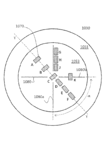
placed at any desired pre-activation reactive region. FIG. 10 illustrates the
placement of integrity sensors 1070 on a rupture disk 1030. As illustrated,
the
rupture disk 1030 has a flange portion 1031 and a rupturable portion 1033. The
rupturable portion 1033 may be provided with one or more features 1080, which
may be used to define a pre-activation reactive region. A sensor 1070 may be
placed adjacent to the pre-activation reactive region. As shown in FIG. 10,
the pre-
activation reactive region may be created¨and the accompanying sensor 1070
correspondingly may be placed¨at any of a number of positions (e.g., A, B, C,
D,
E, F, G, H, J, K, or another position) on the rupture disk 1030. For example,
a pre-
activation reactive region may be defined at position K¨or another position
where
-18-
CA 02769452 2012-01-27
WO 2011/014798
PCT/US2010/043958
the pre-activation reactive region overlaps with a defined area of weakness
(e.g.,
score line 1080b). As another example, a pre-activation reactive region may be
defined at a position such as G, H, or J¨where the pre-activation reactive
regions
is defined adjacent to the defined area of weakness (e.g., one or more score
lines
1080). As yet further examples, a pre-activation reactive region may be
defined at
position such as A, B, C, D, E, or F¨where the pre-activation reactive region
is
defined apart from the defined areas of weakness (e.g., score lines 1080).
Wherever the pre-activation reactive region is created, a sensor 1070 may be
placed at that location.
[075] In one embodiment, a rupture disk 1030 may be provided with four
surface features 1080 in the form of score lines. In this embodiment, the
rupture
disk 1030 is designed to burst along the pattern formed by the score lines
1080,
such that the rupture disk 1030 creates four "petals" upon rupture. The score
lines
1080 may be designed such that at lower pressures, the score lines 1080
actually
act as a support for the rupturable portion 1033. In such an embodiment, as
pressure on the rupturable portion 1033 increases, the rupturable portion 1033
may
experience greater deformation at the center of each 'petal" (e.g., at
position E)
than at each score line 1080. Only after the pressure on the rupturable
portion
1033 increases beyond a threshold level does the rupture disk deform
sufficiently at
the score lines 1080 so as to cause a rupture. In such an embodiment, it has
been
shown to be particularly effective for sensing the integrity of a rupture disk
1030
when a sensor 1070 is positioned at the center of one or more 'petals" of the
rupturable portion 1033. Thus, in one embodiment, an angle a is defined by
score
lines 1080a and 1080b. A line Y-Y bisects the angle a. A sensor may, for
example, be positioned along line Y-Y, such as illustrated by sensors D, E,
and F in
FIG. 10.
[076] The above embodiment is exemplary only, and it is contemplated
that a rupture disk may be designed so that the pre-activation reactive region
is
created in a position other than the center of a "petal" formed by score
lines, and a
sensor may be placed at that alternative pre-activation reactive region. In
addition,
although the rupture disk of FIG. 10 is illustrated as having a circular
contour, it is
contemplated that rupture disks or pressure relief devices of varying shapes
and
dimensions may be used with the present disclosure. No matter the shape of
-19-
CA 02769452 2012-01-27
WO 2011/014798
PCT/US2010/043958
pressure relief device or the pre-activation reactive region, a sensor may be
positioned at or adjacent to the pre-activation reactive region to sense the
integrity
of the rupture disk.
[077] In an embodiment illustrated in FIG. 11A, a rupture disk 1130
includes an indentation 1132 at its apex and a score line 1136 in the form of
an arc
having a first end and a second end. The arc may surround at least a portion
of the
activating portion of the rupture disk 1130. In such an embodiment, the score
line
1136 creates a burst pattern for the rupture disk's activation. The rupture
disk may
burst along the score line 1136, leaving a petal 1131 retained by the hinge
portion
1137 (between the ends of arctuate score line 1136) as illustrated in FIG.
11B. In
this embodiment, a pre-activation reactive region 1135 may be created apart
from
the apex of the rupture disk 1130. For example, where the apex and hinge
portion
1137 define a line Z-Z, a pre-activation reactive region 1135 may be created
along
line Z-Z, on a side of the rupture disk generally opposite of the hinge
portion 1137.
Thus, to monitor the integrity of the rupture disk 1130, a sensor 1170 may be
placed at the pre-activation reactive region 1135. In an alternative
embodiment,
the pre-activation region may be created elsewhere on the rupture disk 1130.
The
sensor 1170 may be placed wherever is appropriate to monitor a pre-activation
reactive region. Although the embodiment illustrated in FIGS. 11A and 11B is
circular, it is contemplated that other geometries may be used with the
disclosure.
Additionally, although FIG. 11A depicts a score line, it is contemplated that
any
suitable designed area of weakness¨including any suitable line of weakness¨
may be used.
[078] While sensors have been described as being attached to or adjacent
to a pre-activation reactive region of a pressure relief device, it is also
contemplated
that other types of sensors may be used with the present disclosure. For
example,
an optical measuring device 1271 may be used, as illustrated in FIG. 12A. The
optical measuring device 1271 may, for example, use a laser beam reflected off
the
surface of a pressure relief device's 1231 pre-activation reactive region to
measure
changes in the pre-activation reactive region. Alternatively, as illustrated
in
FIG. 12B, a radio wave device 1272 may be used as a sensor. Using a radio wave
device 1272, the sensor may measure changes in the pre-activation reactive
region
of a pressure relief device 1232. In yet another alternative embodiment, as
illustrated in FIG. 12C, the sensor may be a vibration detector 1273. The
vibration
- 20 -
CA 02769452 2012-01-27
WO 2011/014798
PCT/US2010/043958
detector 1273 detects vibration frequencies of the pressure relief device
1233. The
vibration frequency of a pressure relief device 1233 may change, for example,
according to the pressure, force, load, temperature, or other conditions
applied to it.
Thus, a change in vibration frequency may indicate a change in the shape or
condition of the pressure relief device 1233.
[079] Before an integrity sensor can be placed at a pre-activation reactive
region, the pre-activation reactive region must be identified. Accordingly,
the
disclosure contemplates a method by which the pre-activation region may be
identified and an integrity sensor applied. According to that method, a strain
gage
(such as strain gage 552 illustrated in FIG. 5A) may be placed on one or more
areas of a pressure relief device, and the strain gage's response may be
measured
when pressures are applied to the pressure relief device. By using a strain
gage at
multiple areas of the pressure relief device, the area or areas with the
highest pre-
activation reaction can be identified. Based on that information, a sensor can
be
installed at or near the pre-activation reactive region so that the pressure
relief
device's integrity may be monitored. Alternatively, the pre-activation
reactive region
may be sensed by a sensor located apart from the pre-activation reactive
region. In
an embodiment wherein the pressure relief device is provided with a designed
area
of weakness, the pre-activation reactive region may or may not overlap with
the
designed area of weakness.
[080] While the above described embodiments of a pressure relief device
integrity sensor have been depicted as utilizing an explosion panel or rupture
disk,
the disclosure is not intended to be limited to this particular structure.
Therefore,
alternative pressure relief devices are intended to be within the scope of
this
disclosure, including all equivalent structures for sealing engagement between
two
sections of different pressures. Also, although the above described
embodiments
have been depicted as monitoring the integrity of a pressure relief device
before
activation, this disclosure is not intended to be limited to that function
alone.
Therefore, embodiments of the described integrity sensor may also monitor
additional parameters of a pressure relief device. Additionally, it is
contemplated
that individual features of one embodiment may be added to, or substituted
for,
individual features of another embodiment. Accordingly, it is within the scope
of
this disclosure to cover embodiments resulting from substitution and
replacement of
different features between different embodiments.
-21 -
CA 02769452 2012-01-27
WO 2011/014798
PCT/US2010/043958
[081] The above described embodiments and arrangements are intended
only to be exemplary of contemplated mechanisms and methods. Other
embodiments will be apparent to those skilled in the art from consideration of
the
specification and practice of the disclosure herein.
- 22 -