Note: Descriptions are shown in the official language in which they were submitted.
ANTI-TIP AND SUSPENSION SYSTEMS FOR WHEELCHAIRS
BACKGROUND
[00021 Some members of society have difficulty walking due to health problems.
To
provide mobility to these people, power wheelchairs have been developed.
Powered wheelchairs
often have six wheels including a pair of center wheels, a pair of rear
wheels, and a pair of front
wheels. Typically, one pair of wheels is driven by, and directly connected to,
a drive. The drive
wheels are typically fixed to the wheelchair and not capable of being
repositioned to
accommodate different sized occupants.
[0003] In cases where the wheelchair is a rear-wheel drive wheelchair the
front wheels
arc configured to ride on the ground surface during normal operation and
provide stability to the
wheelchair during such operation. Typically, these front wheels have the
capability to swivel
about a vertical axis and arc referred to as "casters." When the wheelchair is
driving in a
forward direction the front wheels are configured to overcome an obstacle such
as a curb.
Therefore, these front wheels are connected to a suspension that allows them
to rotate about a
pivot as the wheelchair is overcoming the obstacle. In sonic cases the
suspensions may cause the
front wheels to at first rotate counterclockwise into the obstacle which may
be undesirable.
Additionally, certain suspensions do not maintain the swivel axis of the
casters in a substantially
vertical orientation, which may cause the front casters to catch while the
wheelchair is turning.
[0004] The rear wheels, on the other hand, are fixed and often times referred
to as anti-
tip wheels. The anti-tip wheels may be suspended above the ground plane on
which the
wheelchair rests. The suspension of the anti-tip wheels allows the wheelchair
to clear small
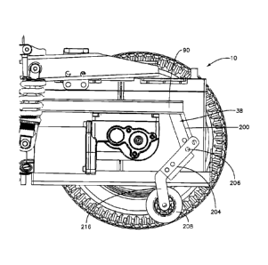
obstacles such as a curb that may be in the path of travel of the wheelchair.
In this case, where
the wheelchair is a rear-wheel drive wheelchair, the anti-tip wheels may
inhibit the wheelchair
from overcoming the obstacle as the wheelchair is backing over the obstacle.
Therefore, it may
be desirable to provide a wheelchair with an anti-tip system that overcomes
this problem.
SUMMARY
[0005l A wheelchair according to one embodiment includes a frame, a pair of
drive
wheels operatively coupled to the frame, a dfive operatively coupled to each
drive wheel, and a
- I -
CA 2813891 2018-01-26
CA 02813891 2013-04-05
WO 2012/047844 PCT/US2011/054702
pair of anti-tip assemblies. Each anti-tip assembly includes a first member, a
second member
pivotally coupled to the first member at a joint that defines a pivot axis, an
anti-tip wheel
rotatably coupled to the second member, and a locking mechanism. The second
member is
capable of pivoting about the pivot axis between an extended position and a
collapsed position.
The locking mechanism is configured to selectively lock the second member in
the extended
position.
[0006] In another embodiment, a wheelchair includes a frame, a pair of drive
wheels
operatively coupled to the frame, and a drive operatively coupled to each
drive wheel to thereby
define respective drive-wheel assemblies. The wheelchair further includes an
anti-tip assembly
operatively attached to each drive wheel assembly. Each anti-tip assembly
includes an anti-tip
wheel. Each anti-tip assembly is configured to have an extended position, and
a collapsed
configuration in which the anti-tip wheel is positioned substantially within a
circumference of
the drive wheel.
DETAILED DESCRIPTION OF THE DRAWINGS
[0007] The foregoing summary, as well as the following detailed description of
a
preferred embodiment of the application, will be better understood when read
in conjunction
with the appended drawings. For the purposes of illustrating the wheelchair
and systems of the
present application, there is shown in the drawings preferred embodiments. It
should be
understood, however, that the application is not limited to the precise
arrangements and systems
shown. In the drawings:
[0008] Fig. lA is a rear perspective view of a wheelchair in accordance with
one
embodiment, the wheelchair including an improved suspension system and a rear
anti-tip system;
[0009] Fig. 1B is a side elevation view of the wheelchair shown in Fig. 1A;
[0010] Fig. 1C is a top plan view of the wheelchair shown in Fig. 1A;
[0011] Fig. 2A is a side perspective view of the wheelchair shown in Fig. 1A,
with a
drive wheel removed for clarity;
[0012] Fig. 2B is a side elevation view of the wheelchair shown in Fig. 2A;
[0013] Fig. 3A is a detailed side elevation view showing the rear anti-tip
system of the
wheelchair shown in Fig. lA in an extended position;
[0014] Fig. 3B is a detailed side elevation view of the anti-tip system shown
in Fig. 3A,
in a partially collapsed position;
[0015] Fig. 3C is a detailed side elevation view of the anti-tip system shown
in Fig. 3B,
in a fully collapsed position;
- 2 -
CA 02813891 2013-04-05
WO 2012/047844 PCT/US2011/054702
[0016] Fig. 4A is a detailed side elevation view of a rear anti-tip system in
accordance
with another embodiment, the anti-tip system including a lock mechanism;
[0017] Fig. 4B is a detailed side elevation view of the rear anti-tip system
shown in Fig.
4A in an unlocked and fully collapsed position;
[0018] Fig. 4C is a detailed side elevation view of the rear anti-tip system
shown in Fig.
4A in a locked and fully extended position; and
[0019] Fig. 5 is a side perspective view of a wheelchair in accordance with
another
embodiment.
DETAILED DESCRIPTION OF ILLUSTRATIVE EMBODIMENTS
[0020] Referring to Figs. 1A-1C, a powered wheelchair 10 is disclosed. In the
illustrated embodiment, the wheelchair 10 is a rear-wheel drive powered
wheelchair. Here, rear-
wheel drive means that the main drive wheels are nominally in the rear of the
wheelchair. The
wheelchair 10 is configured to move in a forward direction along a
longitudinal direction L. It
should be understood, however, that the present invention is not limited to
rear-wheel drive
wheelchairs unless specifically recited in the claims, and this definition is
merely for clarity of
description of the illustrated embodiment.
[0021] As shown in Figs. 1A-1C, the wheelchair 10 includes a frame 14, a pair
of
drive-wheel suspension assemblies 18 that operatively couple respective drive
wheels 22 to the
frame 14, and a pair of front-wheel suspension assemblies 26 that operatively
couple respective
front wheels 30 to the frame 14. The drive-wheel suspension assemblies 18 and
the front-wheel
suspension assemblies 26 are each coupled to respective lateral sides of the
frame 14. As shown,
the wheelchair 10 further includes a pair of anti-tip assemblies 38 that are
operatively coupled to
the frame 14 rearward to the drive wheels 30. The anti-tip assemblies 38 are
configured to
prevent the wheelchair 10 from tipping backwards.
[0022] The frame 14 is a box-like structure that is formed of welded and/or
bolted
square and round tubing and formed plates. The frame 14 includes a forward
transverse shaft 40,
a pair of longitudinally elongate members 44 that are coupled to and extend
rearward from
opposed end portions of the transverse shaft 40, and a seat post 48 that is
rearward to the
transverse shaft 40. The transverse shaft 40 is generally a cylindrical bar
and is elongate in a
direction that is transverse to the longitudinal direction L. As shown in Fig.
1C, the transverse
shaft 40 defines a front end of the frame 14. Also shown in Fig. 1C, the
members 44 are rigidly
connected to the transverse shaft 40 and extend rearward such that each member
44 at least
partially defines a respective lateral side of the frame 14.
- 3 -
CA 02813891 2013-04-05
WO 2012/047844 PCT/US2011/054702
[0023] As shown in Fig. 1A, the scat post 48 extends vertically, and protrudes
from the
frame 14 rearward to the transverse shaft 40. The seat post 48 is configured
to support a
wheelchair seat that is capable of supporting an infirmed occupant. Typical
wheelchair seats
include a seat support, a back support that extends up from the seat support,
and opposed arm
rests that extend forward from the back support.
[0024] As shown in Figs. IA and 1C, the frame 14 further includes a battery
compartment 52 that is configured to support and retain a power supply 56. As
shown, the
battery compartment 52 is generally disposed between the opposed members 44
and rearward to
the seat post 48. In the illustrated embodiment, the power supply 56 is a set
of batteries 60 that
rest within the battery compartment 52 and are accessible from the rear side
of the frame 14.
The batteries 60 are configured to supply power to the wheelchair 10.
[0025] As shown in Figs. 1B and 2A-2B, the wheelchair 10 further includes a
pair of
drive assemblies 70 each coupled to a respective drive wheel 22. Each drive
assembly 70
includes a motor 74 and a gear box 78. Each drive assembly 70 is configured to
drive its
respective drive wheel 22 upon activation by the occupant. As shown in Figs.
2A and 2B, each
motor 74 is mounted in the longitudinal direction such that the motor 74
extends forward from
the drive wheel 22. The drive assemblies 70 including the motors 74 and the
gear boxes 78 are
each translatably coupled to respective drive-wheel suspension assemblies 18.
In this way, each
drive assembly 70 and corresponding drive wheel 22 together define a
respective drive wheel
assembly 82 that is translatably coupled to a respective drive-wheel
suspension assembly 18. To
translatably couple each drive wheel assembly 82 to a respective drive-wheel
suspension
assembly 18 each drive wheel assembly 82 includes a mounting member.
[0026] As shown in Figs. IC and 2A-2B, each drive-wheel suspension assembly 18
is
configured to operatively attach each drive wheel assembly 82 to the frame 14.
As shown, each
drive-wheel suspension assembly 18 includes a swing arm 90 that is rotatably
coupled to the
transverse shaft 40 and a spring 92. Generally, the swing arms 90 are
rotatably coupled to the
end portions of the shaft 40 laterally outside of the members 44. Generally,
the drive wheel
suspension assembly 18 will be described in reference to the left side of the
wheelchair 10 as
shown in Figs. 2A and 2B. It should be understood, however, that the drive
wheel suspension
assembly 18 for the right side of the wheelchair 10 is generally the same as
the drive wheel
suspension assembly 18 for the left side of the wheelchair 10.
[0027] As best shown in Figs. 1C and 2A-2B, each swing arm 90 includes a
forward
swing arm pivot 94, a pair of caster arm pivots 98, and a motor mounting
portion 102 that
extends rearward from the caster arm pivot 98. Each swing arm 90 also includes
a linkage 106
- 4 -
CA 02813891 2013-04-05
WO 2012/047844 PCT/US2011/054702
that extends from the swing arm pivot 94 to the caster arm pivots 98. As shown
in Fig. 2B, the
linkage 106 extends rearward from the swing arm pivot 94 and down at an angle
to the caster
arm pivots 98. Therefore, the caster arm pivots 98 are rearward to and
vertically lower than the
swing arm pivot 94.
[0028] As best shown in Fig. 1C, each swing arm pivot 94 is a barrel 110 that
defines a
horizontal and laterally extending bore 114. The bore 114 is configured to
receive and house the
shaft 40 such that the swing arm 90 is capable of rotating about the shaft 90.
In this way, the
shaft 90 defines a horizontal swing arm pivot axis Sp.
[0029] Similarly and in reference to Fig. 2B, each caster arm pivot 98 is a
barrel 118
that defines a horizontal and laterally extending bore 122. As shown in Fig.
2B, the barrels 118
are generally vertically aligned one on top of the other. Each of the bores
122 of the barrels 118
is configured to receive and house a portion of a respective caster arm such
that the caster arms
are capable of rotating about the barrels 118. In this way, the barrels 118
define horizontal caster
arm pivot axes Cp As shown in Figs. 1C and 2B, both caster arm pivot axes Cp
are rearward to
and vertically lower than the swing arm pivot axis Sp
[0030] As shown in Figs. 1C and 2A-2B, each motor mounting portion 102 of the
swing
arms 90 extends rearward from the caster arm pivots 98 and terminates
proximate to a rear end
of the frame 14. As shown in Fig. 2A, the motor mounting portions 102 each
define a channel
130 that extends along a substantial portion of the motor mounting portion
102. As shown, the
channels 130 are rectangular in shape and include a bottom opening 134 that
extends along the
length of the channel 130. Each channel 130 is configured to receive the
mounting member of a
respective drive wheel assembly 82 such that the mounting member extends
through the channel
opening 134 and the drive assembly 70 is suspended below the swing arm 90. The
entire drive
wheel assembly 82 is capable of translating forward and backward within the
channel 130. This
allows the drive wheels 22 to be placed at different locations along the drive
wheel suspension
assembly 18. Therefore the drive wheel suspension for the wheelchair 10 can be
customized to
the particular occupant of the wheelchair 10. For example, it may be desired
to move the drive
wheels 22 either forward toward the front of the wheelchair or rearward toward
the back of the
wheelchair depending on the weight of the wheelchair occupant. In the
illustrated embodiment,
the drive wheels 22 and in particular the drive wheel assemblies 82 may be
moved along the
swing arm 90 of the drive wheel suspension assembly 18 a distance of at least
3 inches.
[0031] As shown in Fig. 1C, the motor mounting portion 102 of each swing arm
90
includes a plurality of holes 140 that extend through a top surface of the
mounting portion 102
and into the channel 130. As shown, the holes 140 extend along a substantial
portion of the
- 5 -
CA 02813891 2013-04-05
WO 2012/047844 PCT/US2011/054702
mounting portion 102. The holes 140 arc configured to receive fixation members
that lock the
drive wheel assembly 82 in place once the drive wheel assembly 82 has been
properly positioned
along the swing arm 90.
[0032] As shown in Fig. 2B, the drive-wheel suspension assemblies 18 each
further
include a spring 92 that is configured to dampen vibrations or shock
experienced by the
wheelchair 10. As shown, the spring 92 of each drive-wheel suspension assembly
18 extends in
a substantially vertical direction, and is coupled to both the frame 14 and to
a respective drive
wheel assembly 82. In particular, an upper end of each spring 92 is coupled to
a respective
member 44 of the frame 14 and a lower end of each spring 92 is coupled to a
respective motor
74. The springs 92 are configured to absorb shock as the wheelchair 10 moves
over uneven
terrain.
[0033] Referring now to the front wheels 30 of the wheelchair 10 and as shown
in Fig.
2B, each front wheel 30 is part of a caster assembly 150. As shown, the caster
assemblies 150
each include a vertical caster barrel 154 and a wheel support 158 that is
rotatably coupled to the
caster barrel 154. As shown, each caster barrel 154 is substantially
vertically oriented and
includes a bore that is configured to receive a portion of the wheel support
such that the wheel
supports 158 are capable of rotating about their respective caster barrel 154.
In this way, the
caster barrels 154 each define a vertical caster axis A. As shown in Fig. 2B,
the wheel supports
158 extend down from the caster barrels 154 and are coupled to respective
front wheels 30 such
that the front wheels 30 are capable of rotating within the wheel supports 158
along a horizontal
axis. Because the front wheels 30 are operatively coupled to the caster
barrels 154, the front
wheels 30 may swivel as the wheelchair 10 is turned.
[0034] As shown in Figs. IC and 2B, each caster assembly 150 further includes
a pair
of horizontal pivots 164 that are coupled to the caster barrels 154. As shown,
the horizontal
pivots 164 are barrels 168 that are vertically aligned one on top of the
other. Each barrel 168
defines a horizontal laterally extending bore that defines a pivot axis that
is parallel to the caster
arm pivot axes Cp that are defined by the barrels 118 of the swing arms 90.
[0035] As shown in Figs. 1C and 2B, the front-wheel suspension assemblies 26
operatively couple the caster assemblies 150 and in particular the front
wheels 30 to the frame
14. As shown, each front-wheel suspension assembly 26 includes a pair of
caster arms 170, and
a spring 174. Each caster arm 170 is a linkage that is rotatably coupled to a
respective caster
assembly barrel 168 at a front end and a respective swing arm barrel 118 at a
back end. As best
shown in Fig. 2B, an upper caster arm 170 extends from an upper caster
assembly barrel 168 to
an upper swing arm barrel 118. Similarly, a lower caster arm 170 extends from
a lower caster
- 6 -
CA 02813891 2013-04-05
WO 2012/047844 PCT/US2011/054702
assembly barrel 168 to a lower swing arm barrel 118. Each caster arm 170
initially extends
rearward and then down at an angle toward the swing arm barrel 118.
[0036] Each caster arm 170 includes horizontally extending shafts that extend
laterally
from opposed ends of the caster arms 170. The shafts are configured to engage
the bores defined
by the caster assembly barrels 168 and the swing arm barrels 118. Therefore,
as the caster
assemblies 150 are rotated vertically or otherwise in a clockwise direction,
the shafts of the
caster arms 170 may rotate within the barrels 118 and 168.
[0037] As shown in Fig. 2B, each front-wheel suspension assembly 26 further
includes
a spring 174 that is configured to dampen vibrations or shock experienced by
the wheelchair 10.
As shown, each spring 174 of a respective front-wheel suspension assembly 26
extends in a
substantially horizontal direction, and is coupled to the frame 14 and to a
respective upper caster
arm 170. In particular, a rearward end of each spring 174 is coupled to a
respective member 44
of the frame 14 and a forward end of each spring 174 is coupled to a
respective upper caster arm
170. The springs 174 are configured to absorb shock as the wheelchair 10 moves
over uneven
terrain.
[0038] Because of the configuration of the front-wheel suspension assemblies
26, the
wheelchair 10 may traverse obstacles more easily in a forward direction. For
example, by
having two caster arms 170 for each assembly 26 that are rotatably coupled to
both the caster
assembly 150 and to the swing arm 90, the caster arms 170 may be shorter in
length while
maintaining a high pivot for the assembly 26. The shorter arms allow for a
more cost effective
wheelchair. The high pivots allow for all of the forces to go into forcing the
assemblies 26, and
thus the front wheels 30, up (i.e. clockwise) to thereby allow the wheelchair
10 to more easily
traverse an obstacle as the wheelchair 10 moves in a forward direction.
[0039] Furthermore, the configuration of the front-wheel suspension assemblies
26 help
maintain the vertical caster barrels 154 in a substantially vertical
orientation. By maintaining the
vertical orientation, the front wheels 30 will be able to swivel about the
caster barrels 154 more
easily and not get jammed or otherwise impeded during turning of the
wheelchair 10.
[0040] Referring now to Figs. 3A-3C, the wheelchair 10 further includes a pair
of anti-
tip assemblies 38 that are attached to the drive wheel assemblies 82 and thus
operatively attached
to the frame 14. While the anti-tip assemblies 38 are attached to the drive
wheel assemblies 82,
it should be understood that the anti-tip assemblies 38 may be directly
attached to the frame 14,
as desired. In the illustrated embodiment, because the anti-tip assemblies are
attached to the
drive wheel assemblies 82, as the drive wheel assemblies 82 are moved along
the swing arm 90,
the anti-tip assemblies 38 will move as well. As shown, each anti-tip assembly
38 includes a
- 7 -
CA 02813891 2013-04-05
WO 2012/047844 PCT/US2011/054702
first member 200, a second member 204 pivotally coupled to the first member
200 at a joint 206
that defines a pivot axis, and an anti-tip wheel 208 that is rotatably coupled
to the second
member 204. The anti-tip assemblies 38 are configured to or are otherwise
capable of pivoting
between an extended position as shown in Fig. 3A and a collapsed position as
shown in Fig. 3C.
[0041] As shown, each first member 200 extends into a channel 130 of a
respective
swing arm 90 and is coupled to the drive wheel assembly 82 at a first end. In
particular the first
member 200 extends down at an angle from the channel 130 and toward a rear end
of the
wheelchair 10. An opposed end of the first member 200 defines at least part of
the joint 206.
The second members 204 are pivotally coupled to the first members 200 at the
joints 206 such
that the second members 204 may pivot clockwise about the pivot axes defined
by the joints 206,
as shown in Figs. 3B-3C.
[0042] As shown in Fig. 3A, an end of each second member 204 defines a foot
216 that
extends rearward. The anti-tip wheels 208 are rotatably coupled to the ends of
the feet 216. As
shown in Fig. 3A, the anti-tip wheels 208 are positioned at least partially
exterior to the
circumference of the drive wheels 22 when the anti-tip assemblies 38 are in an
extended position.
Additionally, the anti-tip wheels 208 are positioned such that they are
elevated from the ground
when the anti-tip assemblies 38 are in the fully extended position. Therefore,
if the wheelchair
were to hit an obstacle as it is moving in a rearward direction such that the
wheelchair 10 is
caused to pivot or otherwise tip backwards, the extended anti-tip assemblies
38 or at least the
anti-tip wheels 208 will contact the ground and prevent the wheelchair 10 from
fully tipping.
[0043] If the wheelchair were required to traverse an obstacle such as a curb,
the anti-
tip assemblies 38 may be configured to have the second members 204 collapse or
otherwise
pivot clockwise about the joints 206 until the anti-tip wheels 208 are
positioned substantially
within the circumference of the drive wheels 22, as shown in Figs. 3B and 3C.
Preferably the
anti-tip wheels 208 are positioned entirely within the circumference of the
drive wheels 22 as
shown in Fig. 3C. In operation, as the wheelchair 10 moves in a rearward
direction, the anti-tip
wheels 208 will contact the curb. As the wheelchair continues rearward the
second members 204
and thus the anti-tip wheels 208 begin to pivot about the joints 206. Once
fully collapsed the
anti-tip wheels 208 will be within the circumference of the drive wheels 22
and the wheelchair
will be able to more easily traverse the curb.
[0044] In some circumstances it may be desirable to lock the anti-tip
assemblies 38
such that the assemblies 38 are not capable of collapsing. For example, if the
wheelchair is on an
incline and facing up-hill, it may be desirable to lock the anti-tip
assemblies 38 such that if the
wheelchair 10 moves rearward down the hill and contacts a curb, the anti-tip
assemblies 38
- 8 -
CA 02813891 2013-04-05
WO 2012/047844 PCT/US2011/054702
remain in their extended position. To lock the anti-tip assemblies, the anti-
tip assemblies 38 may
further include a locking mechanism 220 that is coupled to either the first
member 200 or the
second member 204. As shown in Figs. 4A-4C, the locking mechanism 200 may
include a
solenoid having a retractable pin 228 and a sliding member 224 attached to the
pin 228. As
shown in Figs. 4A and 4B, each locking mechanism 220 may have an unlocked
position in which
the pin 228 and thus the sliding member 224 are retracted. When retracted, the
second members
208 are capable of pivoting about the joints 206. Alternatively, the locking
mechanisms 220
may have a locked position in which the pins 228 are forced down to thereby
move the sliding
members 224 down such that the sliding members 224 at least partially extend
over the joints
206 and the second members 204, as shown in Fig. 4C. Because the sliding
members 224 extend
over the joints 206 and the second members 204, the second members 204 will
not be capable of
pivoting about the pivot axis defined by the joints 206. Therefore, the anti-
tip assemblies 38 will
be locked in their extended positions. It should be understood, that the
locking mechanisms 220
may include other configurations and are not limited to a solenoid and sliding
member.
[0045] The lockable anti-tip assemblies 38 may include a sensor that indicates
when the
wheelchair 10 is on an incline. Such sensors may include but are not limited
to ball angle
sensors, and gyros. Such sensors may be configured to selectively lock the
anti-tip assemblies
38 depending on the angle of the ground on which the wheelchair is moving.
[0046] Now referring to Fig. 5 the wheelchair may include a front-wheel
suspension
assembly in accordance with another embodiment. As shown, a wheelchair 310
includes a frame
314, a pair of drive-wheel suspension assemblies 318 that operatively coupled
a pair of drive
wheels 322 to the frame 314, and a pair of front-wheel suspension assemblies
326 that
operatively couple a pair of caster assemblies 330 to the frame 314. The drive-
wheel suspension
assemblies 318 are substantially similar to the assemblies 18 of the
embodiment shown in Figs.
1A-1C unless otherwise described.
[0047] The front-wheel suspension assemblies 326, on the other hand, are
slightly
different than the assemblies 26 of the embodiment shown in Figs. 1A-IC in
that the caster arms
are shorter and the spring has a substantially vertical orientation. In that
regard, the suspension
326 includes a pair of caster arms 334 and a spring 338. As shown, the caster
arms 334 are
generally short substantially straight linkages that are vertically aligned
one on top of the other.
The linkages are rotatably coupled to respective barrels of the castor
assemblies 330 and extend
rearward toward respective barrels. As shown, the upper arms 334 extend
rearward and are
rotatably coupled to respective caster barrels 342 that are fixed to the frame
314. The lower arms
- 9 -
CA 02813891 2013-04-05
WO 2012/047844 PCT/US2011/054702
334, on the other hand, extend rearward and are rotatably coupled to
respective caster barrels 346
that are fixed to the swing arms of the drive-wheel suspension assemblies 318.
[0048] Extending rearward of the upper arm 334 is a linkage 350 that is
configured to
couple to the spring 338. As shown, the spring 338 is attached to the motor at
one end and
attached to the linkage 350 at an opposed end. As shown, the spring 338 is
substantially
vertically oriented.
[0049] Like assembly 26, the front-wheel suspension assembly 326 allows the
wheelchair 310 to traverse obstacles more easily in a forward direction. For
example, by having
two caster arms 334 for each assembly 326 that are rotatably coupled to both
the caster assembly
330 and to the swing arm and frame 314, the caster arms 330 may be shorter in
length while
maintaining a high pivot for the assembly 326. The shorter arms allow for a
more cost effective
wheelchair. The high pivots, on the other hand, allow for all of the forces to
go into forcing the
assemblies 326, and thus the front wheels, up (i.e. clockwise) to thereby
allow the wheelchair
310 to more easily traverse an obstacle as the wheelchair 310 moves in a
forward direction.
[0050] Furthermore, like the assemblies 26, the configuration of the front-
wheel
suspension assemblies 326 help maintain the vertical caster barrels of the
caster assemblies 330
in a substantially vertical orientation. By maintaining the vertical
orientation, the front wheels
will be able to swivel about the caster barrels more easily and not get jammed
or otherwise
impeded during turning of the wheelchair 310.
[0051] The foregoing description is provided for the purpose of explanation
and is not
to be construed as limiting the invention. While the invention has been
described with reference
to preferred embodiments or preferred methods, it is understood that the words
which have been
used herein are words of description and illustration, rather than words of
limitation.
Furthermore, although the invention has been described herein with reference
to particular
structure, methods, and embodiments, the invention is not intended to be
limited to the
particulars disclosed herein, as the invention extends to all structures,
methods and uses that are
within the scope of the appended claims. Further, several advantages have been
described that
flow from the structure and methods; the present invention is not limited to
structure and
methods that encompass any or all of these advantages. Those skilled in
personal mobility
technology, having the benefit of the teachings of this specification, may
effect numerous
modifications to the invention as described herein, and changes can be made
without departing
from the scope and spirit of the invention as defined by the appended claims.
Furthermore, any
features of one described embodiment can be applicable to the other
embodiments described
herein. For example, while the suspension assemblies and anti-tip assemblies
have been
- 10 -
CA 02813891 2013-04-05
WO 2012/047844
PCT/US2011/054702
described in relation to a rear-wheel drive wheel chair, it should bc
understood that the
suspensions assemblies and anti-tip wheel assemblies may be used on other
wheelchairs such as
front-wheel drive wheelchairs.
- 11-