Language selection

Search

Patent 2847493 Summary

Third-party information liability

Some of the information on this Web page has been provided by external sources. The Government of Canada is not responsible for the accuracy, reliability or currency of the information supplied by external sources. Users wishing to rely upon this information should consult directly with the source of the information. Content provided by external sources is not subject to official languages, privacy and accessibility requirements.

Claims and Abstract availability

Any discrepancies in the text and image of the Claims and Abstract are due to differing posting times. Text of the Claims and Abstract are posted:

  • At the time the application is open to public inspection;
  • At the time of issue of the patent (grant).
(12) Patent: (11) CA 2847493
(54) English Title: ADJUSTABLE CIRCULATING CHAMBER FOR FIRE INSERTS
(54) French Title: CHAMBRE DE CIRCULATION REGLABLE POUR INSERTS DE CHEMINEE
Status: Granted
Bibliographic Data
(51) International Patent Classification (IPC):
  • F24B 1/195 (2006.01)
  • F24B 1/198 (2006.01)
(72) Inventors :
  • MARCAKIS, EMMANUEL (Canada)
(73) Owners :
  • MARCAKIS, EMMANUEL (Canada)
(71) Applicants :
  • MARCAKIS, EMMANUEL (Canada)
(74) Agent:
(74) Associate agent:
(45) Issued: 2019-12-03
(22) Filed Date: 2014-03-26
(41) Open to Public Inspection: 2014-09-27
Examination requested: 2018-01-11
Availability of licence: N/A
(25) Language of filing: English

Patent Cooperation Treaty (PCT): No

(30) Application Priority Data:
Application No. Country/Territory Date
1305647.8 United Kingdom 2013-03-27

Abstracts

English Abstract

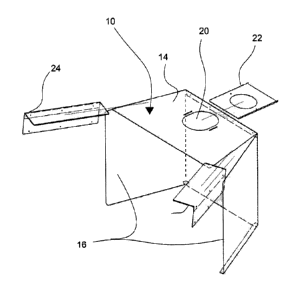
An adjustable circulating chamber for a fireplace insert having a rear wall including two linear sets of perforations forming two bendable side walls, and adapted such that the chamber can be adjusted to fit within fireplace inserts of differing dimensions and a top member including a linear set of perforations forming a flange portion thereon. The flange portion is adapted to be adjustably attached to the rear wall to thereby provide means to vary the height of the top member with respect to the rear wall. The top member further includes an oval- shaped opening therethrough and an adjustable flange member slidably mounted thereto and over the oval-shaped opening and having a circular opening therethrough, such that the oval- shaped opening and the adjustable flange member working together are adapted to receive, adjust, and fit fireplace flue pipes of differing dimensions to the fireplace insert.


French Abstract

La présente invention concerne une chambre à circulation réglable dun poêle encastrable comportant une paroi arrière, y compris deux groupes de trous linéaires qui forment deux parois latérales pliables et qui sont adaptés de telle sorte que la chambre puisse être adaptée dans des poêles encastrables de différentes dimensions et un élément supérieur, y compris un groupe de trous linéaires qui forment une partie de bride en son sein. La partie de la bride est adaptée pour être fixée de manière réglable à la paroi arrière pour fournir ainsi un moyen de faire varier la taille de lélément supérieur en ce qui concerne la paroi arrière. Lélément supérieur comprend en outre une ouverture transversante de forme ovale et un élément bride réglable monté coulissant sur celui-ci et louverture de forme ovale, et ayant une ouverture circulaire transversante, de sorte que louverture de forme ovale et lélément bride réglable travaillant ensemble soient adaptés pour recevoir, ajuster et adapter des tuyaux dévacuation de la cheminée de différentes dimensions au foyer encastrable.
Claims

Note: Claims are shown in the official language in which they were submitted.


8
CLAIMS
1.) An adjustable circulating chamber for a fireplace insert, said adjustable
circulating chamber comprising a rear wall including two linear sets of
perforations forming two bendable side walls, and adapted such that said
chamber can be adjusted to fit within fireplace inserts of differing
dimensions;
and a top member including a linear set of perforations forming a flange
portion
thereon, said flange portion adapted to be adjustably attached to said rear
wall
to thereby provide means to vary the height of said top member with respect to

said rear wall, said top member further including an oval-shaped opening
therethrough and an adjustable flange member slidably mounted thereto and
over said oval-shaped opening and having a circular opening therethrough,
such that said oval-shaped opening and said adjustable flange member working
together are adapted to receive, adjust, and fit fireplace flue pipes of
differing
dimensions to said fireplace insert, a pair of L-shaped brackets adapted to
join
said top member to said side walls of said rear wall, each said L-shaped
bracket
including a track portion along an edge thereon and adapted to slide along and

retain therein a respective edge of said top member, and further including
sheet
metal screws used to secure said L-shaped brackets to said top member and
respective side walls when in place
2.) The adjustable circulating chamber of claim 1, wherein said top member is
formed in the shape of a trapezoid.
3.) The adjustable circulating chamber of claim 1, wherein said top member is
adjustably attached to said rear wall via rivets passing through said flange
portion and through an upper edge portion of said rear wall.
4.) The adjustable circulating chamber of claim 1, wherein said adjustable
flange
portion is slidably and adjustably attached to said top member via wing nuts
passing through holes in said adjustable flange portion and through elongated
slots within said top member.

9
5.) The adjustable circulating chamber of claim 1, wherein said rear wall and
said top member are formed from sheet metal.

Description

Note: Descriptions are shown in the official language in which they were submitted.


CA 02847493 2014-03-26
1 =
Adjustable circulating chamber for fire inserts
FIELD OF THE INVENTION
[001] The present invention relates generally to a circulating chamber for
fireplaces but more particularly to an adjustable circulating chamber for
fire inserts.
BACKGROUND OF THE INVENTION
[002] Fireplace inserts are wood or gas stoves that incorporate a circulating
chamber installed inside the fire chamber of a masonry fireplace to
make the fireplace more efficient. The circulating chamber is an integral
part of the insert as it enhances the flow of heat.
[003] As there is a variation in the sizes of masonry fireplaces,
manufacturers
of fireplace inserts fabricate them with small circulating chambers so as
to fit all sizes. This reduction in dimension restricts air circulation and
efficiency besides being more complicated to install and requiring strong
circulating blowers which run on electricity.

CA 02847493 2014-03-26
2
[004] There hence exists a need for an easier to install, larger and more
efficient circulating chamber for a fireplace insert.
SUMMARY OF THE INVENTION
[005] In view of the foregoing disadvantages inherent in the known devices
now present in the prior art, the present invention, which will be
described subsequently in greater detail, is to provide objects and
advantages which are:
[006] To provide for an adjustable circulating chamber whose width and the
height is adjusted to the size of the existing fireplace, maximizing the
circulating area.
[007] Another advantage of this invention is that the top of the circulating
chamber incorporates an adjustable opening to accommodate the flue
pipe thereby allowing the flue pipe to be easily aligned with the flue
collar of the insert and existing chimney of the masonry fireplace.
[008] In order to do so, the invention comprises an adjustable circulating
chamber for a fireplace insert having a rear wall including two linear sets
of perforations forming two bendable side walls, and adapted such that
the chamber can be adjusted to fit within fireplace inserts of differing
dimensions and a top member including a linear set of perforations

CA 02847493 2014-03-26
3
forming a flange portion thereon. The flange portion is adapted to be
adjustably attached to the rear wall to thereby provide means to vary the
height of the top member with respect to the rear wall. The top member
further includes an oval-shaped opening therethrough and an adjustable
flange member slidably mounted thereto and over the oval-shaped
opening and having a circular opening therethrough, such that the oval-
shaped opening and the adjustable flange member working together are
adapted to receive, adjust, and fit fireplace flue pipes of differing
dimensions to the fireplace insert.
[009] The adjustable circulating chamber further comprises a pair of L-shaped
brackets adapted to join the top member to the side walls of the rear
wall, each of the L-shaped bracket includes a track portion along an
edge thereon and adapted to slide along and retain therein a respective
edge of the top member, and further includes sheet metal screws used
to secure the L-shaped brackets to the top member and respective side
walls when in place.
[0010] The top member is formed in the shape of a trapezoid and is adjustably
attached to the rear wall via rivets passing through the flange portion
and through an upper edge portion of the rear wall.

CA 02847493 2014-03-26
4
[0011] The adjustable flange portion is slidably and adjustably attached to
the
top member via wing nuts passing through holes in the adjustable flange
portion and through elongated slots within the top member.
[0012] The rear wall, the top member, and L-shaped brackets are formed from
sheet metal.
[0013] There has thus been outlined, rather broadly, the more important
features of the invention in order that the detailed description thereof
that follows may be better understood, and in order that the present
contribution to the art may be better appreciated. There are additional
features of the invention that will be described hereinafter and which will
form the subject matter of the claims appended hereto.
[0014] In this respect, before explaining at least one embodiment of the
invention in detail, it is to be understood that the invention is not limited
in its application to the details of construction and to the arrangements
of the components set forth in the following description or illustrated in
the drawings. The invention is capable of other embodiments and of
being practiced and carried out in various ways. Also, it is to be
understood that the phraseology and terminology employed herein are
for the purpose of description and should not be regarded as limiting.

CA 02847493 2014-03-26
[0015] As such, those skilled in the art will appreciate that the conception,
upon
which this disclosure is based, may readily be utilized as a basis for the
designing of other structures, methods and systems for carrying out the
several purposes of the present invention. It is important, therefore, that
5 the claims be regarded as including such equivalent constructions
insofar as they do not depart from the spirit and scope of the present
invention.
[0016] These together with other objects of the invention, along with the
various
features of novelty which characterize the invention, are pointed out with
particularity in the claims annexed to and forming a part of this
disclosure. For a better understanding of the invention, its operating
advantages and the specific objects attained by its uses, reference
should be made to the accompanying drawings and descriptive matter
which contains illustrated preferred embodiments of the invention.
BRIEF DESCRIPTION OF THE DRAWINGS
[0017] Fig. 1 Exploded view of the invention.
[0018] Fig.2 Isometric views of the side and rear of the invention.

CA 02847493 2014-03-26
6
[0019] Fig.3a-b-c Isometric views with close up view of the L-shaped bracket,
top and side view of the invention.
DETAILED DESCRIPTION OF THE PREFERRED EMBODIMENT
[0020] An adjustable circulating chamber (10) having a rear wall (12) with
perforations (18) that allow an installer (not shown) to bend a pair of
side walls (16) according to the size of the fireplace insert (not shown) it
is being fitted within. A top member (14) in the shape of a trapezoid is
attached by means of rivets (21) to the rear wall (12) and a flange
portion with perforations (19) allows an installer to vary the height of the
top (14) to fit the fireplace insert it is being installed within.
[0021] An oval opening (20) on the top (14) with an adjustable flange (22)
having a circular opening that slides on the oval opening (20) allows
adjustment for a round flue pipe (not shown) to be fitted to the fireplace
insert. The adjustable flange (22) is affixed to the top (14) using pre-
installed wing nuts (not shown).
[0022] A pair of L-shaped brackets (24) is used to join the top (14) with the
side
walls (16) of the circulating chamber (10). Each L-shaped bracket (24)
has a track member (26) allowing it to slide along the side edge (28) of

CA 02847493 2014-03-26
7
the top (14) of the circulating chamber (10). The L-shaped brackets (24)
are affixed to the top (14) and side walls (16) using sheet metal screws
(17).
[0023] As to a further discussion of the manner of usage and operation of the
present invention, the same should be apparent from the above
description. Accordingly, no further discussion relating to the manner of
usage and operation will be provided.
[0024] With respect to the above description then, it is to be realized that
the
optimum dimensional relationships for the parts of the invention, to
include variations in size, materials, shape, form, function and manner of
operation, assembly and use, are deemed readily apparent and obvious
to one skilled in the art, and all equivalent relationships to those
illustrated in the drawings and described in the specification are
intended to be encompassed by the present invention.
[0025] Therefore, the foregoing is considered as illustrative only of the
principles of the invention. Further, since numerous modifications and
changes will readily occur to those skilled in the art, it is not desired to
limit the invention to the exact construction and operation shown and
described, and accordingly, all suitable modifications and equivalents
may be resorted to, falling within the scope of the invention.

Representative Drawing
A single figure which represents the drawing illustrating the invention.
Administrative Status

For a clearer understanding of the status of the application/patent presented on this page, the site Disclaimer , as well as the definitions for Patent , Administrative Status , Maintenance Fee  and Payment History  should be consulted.

Administrative Status

Title Date
Forecasted Issue Date 2019-12-03
(22) Filed 2014-03-26
(41) Open to Public Inspection 2014-09-27
Examination Requested 2018-01-11
(45) Issued 2019-12-03

Abandonment History

Abandonment Date Reason Reinstatement Date
2016-03-29 FAILURE TO PAY APPLICATION MAINTENANCE FEE 2016-05-18

Maintenance Fee

Last Payment of $125.00 was received on 2024-03-07


 Upcoming maintenance fee amounts

Description Date Amount
Next Payment if small entity fee 2025-03-26 $125.00
Next Payment if standard fee 2025-03-26 $347.00

Note : If the full payment has not been received on or before the date indicated, a further fee may be required which may be one of the following

  • the reinstatement fee;
  • the late payment fee; or
  • additional fee to reverse deemed expiry.

Patent fees are adjusted on the 1st of January every year. The amounts above are the current amounts if received by December 31 of the current year.
Please refer to the CIPO Patent Fees web page to see all current fee amounts.

Payment History

Fee Type Anniversary Year Due Date Amount Paid Paid Date
Application Fee $200.00 2014-03-26
Reinstatement: Failure to Pay Application Maintenance Fees $200.00 2016-05-18
Maintenance Fee - Application - New Act 2 2016-03-29 $50.00 2016-05-18
Maintenance Fee - Application - New Act 3 2017-03-27 $50.00 2017-01-09
Request for Examination $400.00 2018-01-11
Maintenance Fee - Application - New Act 4 2018-03-26 $50.00 2018-01-11
Maintenance Fee - Application - New Act 5 2019-03-26 $100.00 2019-03-18
Final Fee $150.00 2019-10-16
Maintenance Fee - Patent - New Act 6 2020-03-26 $100.00 2020-02-04
Maintenance Fee - Patent - New Act 7 2021-03-26 $100.00 2021-01-08
Maintenance Fee - Patent - New Act 8 2022-03-28 $100.00 2022-02-11
Maintenance Fee - Patent - New Act 9 2023-03-27 $100.00 2023-03-09
Maintenance Fee - Patent - New Act 10 2024-03-26 $125.00 2024-03-07
Owners on Record

Note: Records showing the ownership history in alphabetical order.

Current Owners on Record
MARCAKIS, EMMANUEL
Past Owners on Record
None
Past Owners that do not appear in the "Owners on Record" listing will appear in other documentation within the application.
Documents

To view selected files, please enter reCAPTCHA code :


To view images, click a link in the Document Description column. To download the documents, select one or more checkboxes in the first column and then click the "Download Selected in PDF format (Zip Archive)" or the "Download Selected as Single PDF" button.

List of published and non-published patent-specific documents on the CPD .

If you have any difficulty accessing content, you can call the Client Service Centre at 1-866-997-1936 or send them an e-mail at CIPO Client Service Centre.


Document
Description 
Date
(yyyy-mm-dd) 
Number of pages   Size of Image (KB) 
Maintenance Fee Payment 2020-02-04 3 52
Maintenance Fee Payment 2021-01-08 2 56
Maintenance Fee Payment 2022-02-11 2 56
Maintenance Fee Payment 2023-03-09 3 61
Cover Page 2014-10-07 1 44
Abstract 2014-03-26 1 22
Description 2014-03-26 7 186
Claims 2014-03-26 2 52
Drawings 2014-03-26 3 92
Representative Drawing 2014-09-02 1 14
Claims 2019-08-01 2 48
Request for Examination / Amendment 2018-01-11 9 285
Maintenance Fee Payment 2018-01-11 1 34
Claims 2018-01-11 4 118
Amendment 2018-10-18 9 275
Claims 2018-10-18 4 127
Interview Record Registered (Action) 2018-11-02 1 29
Amendment 2018-11-13 5 126
Claims 2018-11-13 2 51
Examiner Requisition 2019-01-02 3 201
Amendment 2019-01-21 3 69
Claims 2019-01-21 2 47
Maintenance Fee Payment 2019-03-18 1 28
Interview Record Registered (Action) 2019-07-23 1 23
Amendment 2019-08-01 5 122
Final Fee 2019-10-16 1 28
Representative Drawing 2019-11-14 1 13
Cover Page 2019-11-14 1 43
Maintenance Fee Payment 2024-03-07 3 66
Assignment 2014-03-26 4 75
Change to the Method of Correspondence 2016-01-07 1 24
Maintenance Fee Payment 2016-05-18 1 27
Fees 2017-01-09 1 22