Note: Descriptions are shown in the official language in which they were submitted.
CA 02895600 2015-06-29
ACOUSTIC DATA COMPRESSION TECHNIQUE
FIELD
Embodiments disclosed herein relate to acoustic logging techniques, and more
specifically to acoustic logging techniques for logging while drilling (LWD)
systems.
BACKGROUND
Acoustic logging is frequently used in oil and gas operations to determine
various
properties of an earth formation in which a borehole has been drilled. Many
acoustic logging
data processing and analysis techniques were developed in conjunction with
wireline acoustic
logging tools, which are run in the wellbore after drilling is completed.
These tools are
operatively electrically connected to surface processing equipment by the
wireline, which allows
relatively large quantities of acoustic data to be transmitted to the surface
for analysis. With the
advent of measuring while drilling (MWD) and/or logging while drilling (LWD)
systems, the
wireline connection was no longer available. (Throughout this document LWD
will be used to
refer to both MWD and LWD systems.) Although there are a variety of techniques
for
communicating with LWD tools during the drilling operation, including, for
example,
electromagnetic and mud pulse telemetry, these channels tend to be somewhat
bandwidth
constrained as compared to wireline applications. As a result, many of the
data processing and
analysis techniques that were developed using wireline tools were adapted to
perform more
processing downhole and limit the amount of data that is transmitted to the
surface.
For example, acoustic logging is often undertaken to determine compressional
and shear
wave velocities of the formation. These velocities can subsequently be used to
determine other
parameters of interest, such as, porosity, lithology, and pore pressure, all
of which relate to the
amount of oil or other hydrocarbons in the formation and/or the ease with
which the
hydrocarbons can be recovered. The velocities (as well as Stonely velocities
and other
parameters) can be determined as a function of depth using a technique known
as semblance
processing. Advances in downhole tool design and capabilities have permitted
better semblance
processing results to be generated downhole, yet the problem of getting this
data to the surface
remains. Historically, various (usually lossy) compression techniques have
been used.
Unfortunately, these techniques have often resulted in less-than-optimal
results, as too much data
1
CA 02895600 2015-06-29
is sacrificed to comply with bandwidth limits. The data lost as a result of
these techniques can
often lead to ambiguities in the data transmitted to drilling engineers at the
surface, resulting in
sub-optimal decisions relating to both the steering of the wellbore and
appropriate completions
techniques. Thus, what is needed is a better technique for compressing
acoustic data measured
and/or generated by a downhole LWD system so that more and/or better
information can be
transmitted to the surface despite the constraints of commonly used downhole
telemetry systems.
Although disclosed in the context of LWD systems, such data compression
techniques could also
be used in wireline systems.
SUMMARY
In one broad aspect, a method of acquiring and processing acoustic data in a
logging
while drilling (LWD) system is provided. The method comprises firing an
acoustic transmitter.
The method further comprises receiving acoustic signals (which have interacted
with a
formation) at a plurality of receivers spaced apart from the transmitter. This
step is followed by
semblance processing the received acoustic signals to generate a semblance
projection for each
of a plurality of depths. The final step comprises telemetering one or more
peak values of said
semblance projection for each of the plurality of depths to the surface. The
one or more
telemetered peak values include at least a slowness measurement and a
coherence value.
In another broad aspect, a logging while drilling (LWD) system comprising an
LWD
borehole instrument is provided. The borehole instrument comprises a pressure
housing, a drill
bit operatively coupled to a lower end of the borehole instrument, and a
connector which
operatively connects the borehole instrument to a drill string at an upper end
of the borehole
instrument. The borehole instrument further comprises an acoustic transmitter.
The borehole
instrument also comprises an acoustic receiver assembly comprising a plurality
of receivers
axially spaced from the transmitter. The borehole instrument further comprise
an electronics
section that provides power and control circuitry for the acoustic transmitter
and acoustic
receiver assembly. The electronics section further comprises a downhole
processor unit which is
configured to fire the acoustic transmitter. The downhole processor unit is
also configured to
receive acoustic signals (which have interacted with a formation) from the
acoustic receiver
assembly. The downhole processor unit is further configured to perform
semblance processing of
the received acoustic signals to generate a semblance projection for each of a
plurality of depths.
2
CA 02895600 2015-06-29
The downhole processor unit also telemeters one or more peak values of said
semblance
projections for each of the plurality of depths to the surface. The one or
more telemetered peak
values include at least a slowness measurement and a coherence value.
In another broad aspect, an electronics section for a logging while drilling
(LWD) system
is provided. The LWD system comprises a downhole processor which is configured
to fire an
acoustic transmitter of an LWD tool. The downhole processor is also configured
to receive
acoustic signals (which have interacted with a formation) from an acoustic
receiver assembly of
an LWD tool. The acoustic receiver assembly comprises a plurality of receivers
spaced apart
from the acoustic transmitter. The downhole processor also performs semblance
processing of
the received acoustic signals to generate a semblance projection for each of a
plurality of depths.
Finally, the downhole processor telemeters one or more peak values of said
semblance
projections for each of the plurality of depths to the surface. The one or
more telemetered peak
values include at least a slowness measurement and a coherence value.
BRIEF DESCRIPTION OF THE DRAWINGS
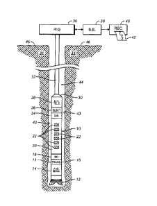
Figure 1 illustrates an exemplary LWD acoustic logging system;
Figure 2 illustrates an exemplary plot of acoustic signals received by a
plurality of
receivers of an acoustic logging system;
Figure 3 illustrates an exemplary semblance plot based on acoustic signals
received by a
plurality of receivers of an acoustic logging system;
Figure 4 illustrates an exemplary semblance projection based on the semblance
plot of
Fig. 3;
Figure 4B illustrates an example of a plurality of semblance projections
assembled into a
variable density log (VDL);
Figure 5A illustrates an exemplary log generated from semblance projections as
a
function of depth;
Figure 5B illustrates the log of Fig. 5A using the compression techniques
disclosed
herein;
3
CA 02895600 2015-06-29
Figure 6A illustrates the exemplary log of Fig. 5A with compression and shear
velocity
as a function of depth superimposed thereon; and
Figure 6B illustrates the log of Fig. 6A using the compression techniques
disclosed
herein.
DETAILED DESCRIPTION
Fig. 1 illustrates an LWD acoustic system disposed in a borehole drilling
environment.
The LWD borehole instrument or "tool" component of the borehole assembly is
designated as a
whole by the numeral 10, and comprises a pressure housing 11, which is
typically a drill collar.
The tool 10 is disposed within a well borehole 44 defined by borehole walls 43
and penetrating
earth formation 34. A drill bit 12 terminates a lower end of the tool 10, and
a connector 30
terminates an upper end of the tool. The connector 30 operationally connects
the tool 10 to a
lower end of a drill string 32. The upper end of the drill string terminates
at a rotary drilling rig
36, which is known in the art and is illustrated conceptually at 36.
Again referring to Fig. 1, the tool 10 comprises a transmitter 16 and a
receiver assembly
20. An acoustic isolation section 18 separates the transmitter 16 from the
receiver assembly 20.
The receiver section 20 comprises a plurality of receivers 22 axially spaced
from the transmitter
16. Six receivers are illustrated for purposes of discussion, although more or
fewer receivers can
be used. The receivers 22 are also shown axially aligned, although axial
alignment is not
required if the transmitter firing sequence is suitably adjusted.
In the embodiment shown in Fig. 1, the tool comprises a directional section 24
that
provides a real time measure of azimuthal angle therefore provides azimuthal
orientation of the
tool 10 within the borehole 44. The directional section 24 can comprise
magnetometers,
accelerometers, or both magnetometers and accelerometers. The tool 10 can
optionally comprise
an auxiliary sensor section 14 with one or more auxiliary sensors responsive
to a variety of
borehole environs parameters. It should be understood that the acoustic
measurement system
disclosed herein does not necessarily require measurements from the auxiliary
sensor section 14.
An electronics section 26 provides power and control circuitry for the
acoustic transmitter 16,
receiver elements 22 of the receiver section 20, the directional section 24,
and any auxiliary
sensors in the auxiliary sensor section 14. Power is typically supplied by
batteries, but may be
supplied by a mud powered turbine generator (not shown).
4
CA 02895600 2015-06-29
Still referring to Fig. 1, a down-hole processor unit (not shown) is
preferably located
within the electronics section 26. The processor receives and processes
responses from the
receiver elements 22. The processor also controls, among other things, the
firing of the
transmitter 16 as a function of information received from the directional
section 24. The
electronics section 26 is operationally connected to a down-hole telemetry
unit 28. Data, from
elements within the tool 10, whether processed downhole as parameters of
interest or in the form
of "raw" data, are telemetered to the surface 46 of the earth by means of a
suitable telemetry
system. Suitable telemetry systems include a mud pulse system, and
electromagnetic telemetry
system, or an acoustic telemetry system that uses the drill string 32 as a
data conduit. The
telemetered data are received by an up-hole telemetry element (not shown)
preferably disposed
in a surface equipment module 38. As the borehole assembly comprising the
logging tool 10 is
conveyed along the borehole 44 by the drill string 32, one or more parameter
of interest, or
alternately raw data, are input to a recorder 40. The recorder 40 tabulates
the data as a function of
depth within the borehole 44 at which they are measured. The recorder output
42 is typically a
"log" of the data as a function of borehole depth. The data can alternately be
recorded in down-
hole processor memory (not shown), and subsequently downloaded to the surface
equipment
module 38 when the tool 10 is returned to the surface 46 during or after the
drilling operation is
completed. The downloaded data are typically processed further within the
surface equipment
module 38 to obtain additional parameters of interest that cannot be
determined in the down-hole
processor unit.
As stated previously, the pressure housing 11 is typically a steel drill
collar with a conduit
through which drilling fluid flows. Elements of the tool 10 illustrated
conceptually in Fig. 1 are
typically disposed within the wall of the drill collar pressure housing 11.
Fig 2 illustrates acoustic signals 100 received by the plurality of receivers
22. Each
acoustic signal is a plot of amplitude (in arbitrary units) versus time. The
lowermost signal
corresponds to the signal from the receiver 22 nearest transmitter 16, with
the next higher signal
corresponding to the next nearest receiver, etc. As can be seen, the receivers
located farther from
the transmitter will experience signal arrival at a later time. Semblance
processing techniques can
be applied to acoustic signals 100 like those illustrated in Fig. 2 to
generate a semblance map like
that illustrated in Fig. 3.
5
CA 02895600 2015-06-29
Fig 3 shows a conceptual slowness time coherence ("STC") map (a/k/a "semblance
map") of an acoustic data set like that illustrated in Fig. 2. The semblance
map has been
conceptualized for brevity and comprises a plot of slowness (ordinate) as a
function of arrival
times from the wave field responses recorded by the receivers 22 shown in Fig.
1. Slowness and
arrival times are expressed in units of microseconds per foot (us/ft) and
microseconds (us),
respectively. Contours 52, 54 and 56 indicate values of increasing magnitude
of coherence,
typically expressed as a percentage. In practice, semblance maps are typically
depicted in color.
For example, low coherence values might be depicted in blue to green shades,
with intermediate
coherence values depicted by yellow shades, with the highest coherence values
depicted by
orange to red shades. The exemplary semblance map illustrated in Fig. 3 shows
a compressional
wave arrival at lower left. Moving upward and to the right (i.e., slower/later
arrivals), the
compressional wave arrival is followed by a shear arrival, and other arrivals,
which could be
Stonely or fluid wave arrivals, etc.
Fig 4 illustrates a semblance projection of the semblance map illustrated in
Fig. 3. In this
plot, semblance expressed as a percentage (ordinate) is plotted as a function
of slowness (us/ft).
This semblance projection provides key information to a drilling engineer,
primarily in the
values of the peaks for the various arrivals. For example, the peak 60
indicates the compression
velocity (slowness) of the formation, peak 62 indicates the shear velocity
(slowness) of the
formation, and peak 64 indicates the Stonely velocity (slowness) of the
formation or a borehole
fluid arrival.
Each of the foregoing plots discussed with reference to Figs. 2, 3 and 4 are
indicative of
parameters measured only at a certain depth. In practice, it is frequently
desirable to obtain
semblance projections like that illustrated in Fig. 4 at a plurality of
depths. This collection of
semblance projections can be used to generate a log of pertinent velocities
(or other parameters
derived therefrom) as a function of depth. An example of such a log is
illustrated in Fig. 4B. In
Fig. 4B, increasing depth is illustrated downward on the vertical axis.
Slowness is illustrated on
the horizontal axis, with slowness increasing (velocity decreasing) in the
rightward direction.
Semblance is illustrated on the left as a curve and on the right as a variable
density log (VDL) by
shading the curves, with darker values corresponding to higher semblance
values.
6
CA 02895600 2015-06-29
Fig 5A illustrates an exemplary variable density log. Fig. 6A illustrates a
variation of
Fig. 5A in which a compressional velocity as a function of depth curve 601 has
been
superimposed. Additionally, a shear velocity as a function of depth curve 602
has been
superimposed. Further inspection of Fig. 6A shows that there may be an
additional relatively
slower arrival in region 603 illustrated at the far right of Fig. 6A. However,
interpretation of
such an arrival is somewhat complicated by the faintness and relatively low
semblance. In any
case, this type of information is highly useful to a drilling engineer in
seeking to steer a wellbore
for optimal recovery of hydrocarbons.
While the plots illustrated in Fig. 5A and 6A are highly useful, transmission
of such
curves in real time during a LWD operation requires a prohibitively large
amount of data. Thus,
historically, one approach has been to only transmit the slowness value
corresponding to peak
semblance for each depth. As an example, eight bits might be allocated to each
of two peaks for
a given depth; the two peaks corresponding to a compression velocity and a
shear velocity at that
depth. This allows curves 601 and 602 to be regenerated at the surface. One
significant problem
with this approach has been realized when transitioning from a fast to a slow
formation. In such
a transition, the compression slowness may fairly suddenly transition from a
relatively low value
(in the fast formation) to a higher value in the slow formation) that
generally corresponds to the
shear velocity in the faster formation. In such a case, another peak may be
lost due to sampling
frequency or other measurement limitations. In such a case, without all of the
other data being
sacrificed as a result of the somewhat crude compression techniques, it might
not be recognized
that there had been a transition from a fast to a slow formation. Obviously
this information
would be of significant importance to the drilling engineer, and thus its
masking by the prior art
compression technique is somewhat problematic.
To address these deficiencies, other compression techniques based on wavelet
compression have been introduced. These techniques generally operate as
follows: for each
depth, a semblance projection like that illustrated in Fig. 4 is divided along
the horizontal axis
into multiple bins, e.g., 96 bins. If an 8-bit value for each bin were to be
transmitted, a total of
768 (96x8) bits per depth would be required. However, using wavelet
compression this can be
compressed into 32 bits per depth. This requires a "smearing" of the semblance
projection,
caused by collapsing six bins into one, for a total of 16 bins. While this
compression technique
is effective, the resultant "smearing" can cause the peak to be shifted to the
left or right,
7
CA 02895600 2015-06-29
corresponding to a decrease or increase in slowness. The introduced
measurement error is itself
undesirable for obvious reasons.
To overcome these deficiencies of prior compression techniques, the inventor
has
developed the following compression technique. First, for each depth, velocity
values
corresponding to the first three peaks of the semblance projection (e.g.,
peaks 60, 62, and 64
illustrated in Fig. 4) will be telemetered to the surface. In addition to the
velocity values
corresponding to the peaks, the semblance value (a/k/a "coherence") will also
be transmitted.
Transmission of the semblance values makes it easier to follow movement of the
peak as a
function of depth. In other words, sending the peak plus the coherence allows
an image
corresponding to that in Figs. 5A and 6A to be reproduced. Such reconstructed
images are
illustrated in Figs. 5B and 6B, respectively. In general the added coherence
data allows the
curvature of the peak in the vicinity of the peak to be inferred. In other
words, giving color to
the point allows correlation between depths of which peaks are which. Thus,
even in the event
of a dramatic shift from a faster formation to a slower formation, compression
velocities can still
be associated with compression velocities, shear with shear, etc.
Additionally, further refinement possible based on the known properties of the
measurement system. For example, peak width is generally a function of
transmitter frequency
and receiver spacing. Thus, when gentlated reconstructed curves illustrated in
Figs. 5B and 6B,
the plotting program can be customized to reintroduce appropriate curvature.
As can be seen by
comparing Figs. 5B to 5A and 6B to 6A, the compression technique described
herein conveys all
of the pertinent information in the original plots while dramatically reducing
the number of bits
required to convey the information. As can be further seen, by comparing Fig.
6B to Fig. 6A, it
is quite easy to trace the velocities as a function of depth for the
compression velocity 601a, the
shear velocity 602a, and the third arrival 603a, which quite difficult to make
out in Fig. 6A.
In one embodiment, 10 bits can be allocated to each of three peaks, with 7
bits for the
velocity (slowness) value and three bits allocated to the coherence value of
each peak. This
allows two extra bits to be used for enhanced precision while still matching
the total of 32 bits
per depth realized by the wavelet compression technique described above. Of
course, other
numbers of bits or bit allocations could also be used while using the same
principle of
compression.
8
CA 02895600 2015-06-29
Some portions of the detailed &scription were presented in terms of processes,
programs
and workflows. These processes, programs and workflows are the means used by
those skilled in
the data processing arts to most effectively convey the substance of their
work to others skilled in
the art. A process or workflow is here, and generally, conceived to be a self-
consistent sequence
of steps (instructions) contained in memory and run or processing resources to
achieve a desired
result. The steps are those requiring physical manipulations of physical
quantities. Usually,
though not necessarily, these quantities take the form of electrical, magnetic
or optical signals
capable of being stored, transferred, combined, compared and otherwise
manipulated. It has
proven convenient at times, principally for reasons of common usage, to refer
to these signals as
bits, values, elements, symbols, characters, terms, numbers, or the like.
It should be borne in mind, however, that all of these and similar terms are
to be
associated with the appropriate physical quantities and are merely convenient
labels applied to
these quantities. Unless specifically stated otherwise as apparent from the
following discussion,
it is appreciated that throughout the description, discussions utilizing terms
such as "processing,"
"receiving," "calculating," "determining," "displaying," or the like, refer to
the action and
processes of a computer system, or similar electronic computing device, that
manipulates and
transforms data represented as physical (electronic) quantities within the
computer system
memories or registers or other such information storage, transmission or
display devices.
The present invention also relates to an apparatus for performing the
operations herein.
This apparatus may be specially constructed for the required purposes, or it
may comprise a
general-purpose computer, selectively activated or reconfigured by a computer
program stored in
the computer. Such a computer program may be stored in a computer readable
storage medium,
which could be, but is not limited to, any type of disk including floppy
disks, optical disks, CD-
ROMs, an magnetic-optical disks, read-only memories (ROMs), random access
memories
(RAMs), EPROMs, EEPROMs, magnetic or optical cards, application specific
integrated circuits
(ASICs), or any type of media suitable for storing electronic instructions,
and each coupled to a
computer system bus. Furthermore, the computers referred to in the
specification may include a
single processor, or may be architectures employing multiple processor designs
for increased
computing capability.
9
CA 02895600 2015-06-29
The systems and techniques described herein are not inherently related to any
particular
computer or other apparatus. Various gs.neral-purpose systems may also be used
with programs
in accordance with the teachings herein, or it may prove convenient to
construct more
specialized apparatus to perform the required method steps. The required
structure for a variety
of these systems will appear from the description above. In addition, the
present invention is not
described with reference to any particular programming language, software
application, or other
system. It will be appreciated that a variety of languages, applications,
systems, etc. may be used
to implement the teachings of the present invention as described herein, and
any references to
specific languages, applications, or systems are provided only for purposes of
enabling and
disclosing the best mode of practicing the invention.