Note: Descriptions are shown in the official language in which they were submitted.
CA 2903177 2017-04-06
ICE SKATE BLADE GUARD WITH SAFETY FEATURE
DESCRIPTION
[0001] The invention comprises a safety feature for an ice skate blade guard,
a skate
guard including the safety feature, and/or a method of manufacturing or using
the same.
BACKGROUND
[0002] Field of the Disclosure
[0003] The present invention relates generally to a device worn on an ice
skate to
partially enclose and/or otherwise protect the blade, and, more specifically,
to such a device
including a safety feature to limit or prevent falls if the skater enters the
ice, that is, steps, glides,
slides, jumps, or otherwise moves onto the ice, with the device still on the
ice skate. The use of
the preferred device would b,e recognized as extremely beneficial by ice
skaters who have
accidentally left their ice skate blade guards in place, and, upon entering
the ice, have sustained
a fall due to either undesirable type or direction of slippage of the blade
guards upon the ice
surface. Especially common are injuries sustained when one or both of the
wearer's skates slide
sideways out from under the wearer. Such injuries may be common, in part,
because a skater
frequently accelerates upon entering (moving onto) the ice by pushing his/her
feet and skates in
a direction having a vector transverse to the length of the skate blades.
[0004] Related Art
[0005] Ice skates and ice skate blade guards are well known. For example, see
Figures
22 and 23, where an example, prior art ice skate S and an example prior art
blade guard BG
(also "guard") are shown. The blade guard BG of Figure 23 may be manufactured
or retro-fit
with an embodiment of the invented slip-prevention system, underneath the
guard main body.
The guards are used to protect ice skate blades B from damage or dulling, to
prevent injury to
persons coming in contact with sharp skate blades, and/or to protect floors
and other surfaces
upon which the skater walks. Also well-known is the fact that blade guards are
designed to be
CA 2903177 2017-04-06
worn by the skater only when not upon ice. For example, when a skater is
waiting a turn to
skate, the blade guards are installed upon the skates to protect the skate
blades from damage by
surfaces other than ice, such as wood or concrete surfaces. Some skaters also
use the blade
guards when they don their skates at a location distant from the ice, where-
after they wear the
skates and guards through a building or from a parking lot to the ice, for
example.
[0006] If blade guards are not removed before entering the ice, serious injury
may occur
as the result of a fall because the blade guard interferes with the normal
interaction between the
skate blade and the ice and/or interfering with normal skating movements by
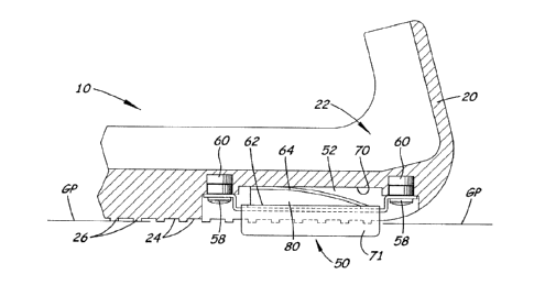
the skater. This
interference may depend on the material from which the guard is made, and may
include
"catching" of the guards on the ice as the skater tries to glide forward
across the ice as he/she
would typically do upon entering the ice, or, more frequently, slippage or
other lack of control
created because the broad, non-sharp base of many guards slides on the ice.
Consistent with
their original object and aim, conventional guards do not comprise the same
shape, sharp edges,
and/or material that a skate blade comprises, and so the guards seldom or
never allow a skater to
move on the ice in a controlled and safe way until the skater can remove the
guards for leaving
the ice or for carrying on with the intended skating.
[0007] The skate and blade guard main body shown in Figures 22 and 23 are only
examples of many styles and types of skates and guards, as will be understood
by those of skill
in this field. There are many other styles of figure skates, and there are
many styles of hockey
and racing skates. Features common to many skates are a front "toe" T of the
blade and a rear
"heel" H of the blade, and openings 0 between the blade and the sole of the
skate shoe. One or
more of these features are typically used for connection of conventional blade
guards to the
skate/blade. For example, the front and rear portions of the guard BG main
body shown in
Figure 23 slide apart longitudinally to receive and extend around the toe T
and the heel H of the
blade, whereafter the portions may be slid back together to capture the blade.
Other guards may
be somewhat flexible/bendable, so they can be pushed or pulled onto the blade
and around the
toe and heel. Other guards, for example ones enclosing only one of the toe T
and heel H rather
than both, will at least partially rely on structure extending through one or
both openings 0, or a
loop over the heel H. to hold the guard on the blade. Therefore, many
different skates and many
2
CA 02903177 2015-09-08
different guards may be manufactured or retro-fit with embodiments of the
invented safety
mechanism.
[0008] The blade of an ice skate is configured to bite into ice during many
movements.
The blade may be slightly concave edge to edge, with sharp side edges
(corners), and in some
designs, slightly convex end to end. Many skating actions require the skater
to be "on an edge",
wherein an edge of the blade is "biting" or "cutting" into the ice while the
skater's moves in a
curved direction on the ice, wherein said "biting" or "cutting" provides
control. One may easily
see the effect of such biting or cutting, that is, corresponding marks on the
ice that result
because the skate blade cuts into, shaves, or gouges the ice, which is
relatively softer than the
metal skate blade.
[0009] Conventional ice skate blade guards, on the other hand, have broad
bases,
typically of rigid or generally rigid polymeric or rubber-like materials. Some
bases have
transverse channels across the base of the guard, for example, for cooperating
with attachment
means that connect to the skate. Some blade guards may be made of flexible or
soft, even
fabric, materials. Conventional guards, therefore, may be described as having
bases for
contacting the ground or floors that are broad and/or entirely or
substantially non-sharp, for
example, not having any edge or surface that is adapted to bite into the ice.
Skate blade guards
from the patent literature include: U.S. Patent #4,252,345; Cabral,U.S.Patent
#4,264,090,
Davies; U.S.Patent #4,365,828, Hall, et.al.; U.S. Patent #4,382,615, Gronborg,
et.al; U.S. Patent
#4,382,616, Olivieri; U.S. Patent #4.392,674, Evon; U.S. Patent #4,546,999,
Lehr; U.S. Patent
#4,673,196, Hall; U.S. Patent #5,941,568, White 11; U.S. Patent #6,142,528,
Riley; and U.S.
Patent #6,666,479, Maddaleni.
SUMMARY
[0010] The invented device and/or method comprise a guard that at least
partially
encloses, covers, and/or otherwise protects at least a portion of the blade of
an ice skate,
preferably the sharpened edges of the blade, and that is adapted to limit or
prevent sideways-slip
to minimize or prevent injury to the skater. The guard comprises a slip-
prevention system
comprising at least one element/member that limits or prevents sideways-slip
on the ice, in case
the guard is accidentally left installed upon the icc skate when the skater
moves onto the ice (or
3
CA 02903177 2015-09-08
"enters the ice"). The at least one element may comprise a longitudinally-
extending bar, blade,
protrusion, ridge, or other member that is adapted, for example, by being
narrow, sharp, and/or
having sharp side edge(s), to bite-into (cut into, grip, engage) or otherwise
interact with the ice
to limit or stop sideways motion. Urged against the ice by a bias and/or by
weight of the
wearer, the elongated element(s) is/are adapted to allow at least some safe
forward movement,
but to limit(s) or prevent(s) sideways slipping. The wearer is thus typically
protected from
falling until he/she may stop, and/or safely return to the rink-side, to
remove the guards for
skating if desired.
BRIEF DESCRIPTION OF THE DRAWINGS
[0011] Figure 1 is a side view of one embodiment of an improved ice skate
blade guard
that comprises an embodiment of the slip-prevention system, wherein dual-blade
assemblies are
installed near the toe-end and the heel-end of the guard.
[0012] Figure 2 is a bottom view of the guard of Figure l
[0013] Figure 3 is a longitudinal, cross-sectional, partial side view of the
guard of
Figures 1 and 2, for example the toe-end, showing in detail a dual-blade
assembly of Figures 1
and 2. No weight is being placed on the guard, as if the wearer has raised
his/her foot up from
the floor/ground/ice.
[0014] Figure 4 is a cross-sectional, partial view of the guard of Figures 1
and 2, as in
Figure 3 except that the wearer has put his/her foot down on ice, so that the
guard main body
rests on the ice, and the dual-blade unit is biased down from the guard main
body to be pressed
against/into the ice. The dual-blade unit has moved slightly up into the guard
main body due to
being pressed against/into the ic,e, but the bias still forces the dual-blade
unit below the guard
main body to bite into the ice sufficiently to limit/prevent sideways movement
when sideways
force is applied to the skate and guard, that is, when incipient sideways
movement
occurs/begins.
[0015] Figure 5 is a cross-sectional end view along the line 5-5 in Figure 4.
[0016] Figure 6 is a top perspective view of the dual blade assembly of Figure
1 - 5,
detached from the guard and showing one embodiment of the bias-cushion used in
addition to
the bias-spring of the assembly.
4
CA 02903177 2015-09-08
[0017] Figure 7 is an exploded top perspective view of the pieces-parts of thc
dual-blade
assembly of Figures 1 ¨ 6.
[0018] Figure 8 is a cross-sectional side view of the dual-blade assembly of
Figs. 1 - 7.
[0019] Figure 9A is an end view along the line 5 -5 in Figure 4, as in Figure
5 except
enlarged for convenience in calling-out portions of the dual-blade assembly as
installed in the
main body of the guard and calling-out the blade plane, guard plane, and ice
plane.
[0020] Figure 9B is an enlarged end view of an alternative embodiment wherein
the bias
is adapted to be so forceful so that the blades, shown biting into the ice,
carry the guard, skate,
and wearer above the plane of the top surface of the ice, and limit/prevent
sideways movement.
[0021] Figure 10 is an enlarged bottom view of one end of the embodiment of
Figures 1
and 2, again for convenience in calling-out portions of the dual-blade
assembly as installed in
the main body of the guard.
[0022] Figure 11 is a top perspective view of an alternative dual-blade
assembly,
comprising a two-spring dual-blade unit, two cushions, and a retainer for
being connected to the
guard by bolts or other fasteners.
[0023] Figure 12 is an exploded view of the device of Figure 11.
[0024] Figure 13 is a top perspective view of yet another alternative dual-
blade
assembly, comprising a two-spring dual-blade unit wherein the springs extend
toward each
other, two cushion portions of a single cushion unit, and a retainer for being
connected to the
guard by bolts or other fasteners.
[0025] Figure 14 is an exploded view of the device of Figure 13.
[0026] Figure 15 is a top perspective view of yet another alternative dual-
blade
assembly, similar to that in Figures 11 and 12, except that the relative
dimensions of the dual-
blade unit and the retainer have been altered, as may be useful depending on
the dimensions of
the skate guard body, and/or to maintain the two blades in a morc exposed
position for better
contact with, and biting into, the ice during incipient sideways movement.
[0027] Figure 16 is an exploded view of the device of Figure 15.
[0028] Figure 17 is a side view of an example blade guard with an alternative
slip-
prevention system, installed near the toe and near the heel of the blade
guard, that is one
embodiment of a fixed slip-prevention system that does not move relative to
the guard body.
5
CA 2903177 2017-04-06
[0029] Figure 18 is a bottom view of the embodiment of Figure 17.
[0030] Figure 19 is a cross-sectional end view of the embodiment of Figures 17
and 18,
viewed along the line 19 ¨ 19 in Figure 18.
[0031] Figure 20 is a top perspective view of the dual-blade member of the
embodiment
of Figures 17¨ 19.
[0032] Figure 21 is a bottom perspective view of the dual-blade member of the
embodiment of Figures 17 ¨ 20.
[0033] Figure 22 is a perspective view of one example of a conventional ice
skate.
[0034] Figure 23 is a perspective view of the ice skate of Figure 22 with one
example of
a conventional blade guard main body installed on the ice skate.
[0035] Figure 24 is a bottom view of an alternative embodiment of a slip-
prevention
system on a skate guard main body, featuring a blade unit that has two
downwardly-depending
blades that are each at an obtuse angle relative to the top plate of the blade
unit and the guard
plane, and wherein this blade unit is another embodiment of a fixed slip-
prevention system that
does not move relative to the guard body.
[0036] Figure 25 is an end view of only the blade unit (with fasteners) of
Fig. 25,
viewed from the line 25-25 in Fig. 24.
[0037] Figure 26 is a bottom view of an alternative embodiment of a slip-
prevention
system on a skate guard main body, and featuring a blade unit that has three
downwardly-
depending blades that are each at a right angle relative to the top plate of
the blade unit and the
guard plane, wherein this blade unit is another embodiment of a fixed slip-
prevention system
that does not move relative to the guard body.
[0038] Figure 27 is an end view of only the blade unit (with fasteners) of
Fig. 26,
viewed from the line 27-27 in Fig. 26.
[0039[ Figure 28 is a bottom view of an alternative embodiment of a slip-
prevention
system on a skate guard main body, featuring a blade unit that has three
downwardly-depending
blades that are each at a right angle relative to the top plate of the blade
unit and the guard plane,
and also featuring a bracket fastened to the main body and extending across
and below the blade
6
CA 02903177 2015-09-08
unit to hold the blade unit on the skate guard main body, for example, ill a
recess in the main
body wherein the blade unit may slide up and down relative to the recess.
[0040] Figure 29 is an end view of only the blade unit and bracket (with
fasteners) of
Fig. 28, viewed from the line 29-29 in Fig. 28.
[0041] Figure 30 is a bottom view of an alternative embodiment of a slip-
prevention
system on a skate guard main body, and featuring a blade unit that has many
downwardly-
depending protrusions/ridges, wherein this blade unit is another embodiment of
a fixed slip-
prevention system that does not move relative to the guard body.
[0042] Figure 31 is an end view of only the blade unit (with fasteners) of
Fig. 30,
viewed from the line 31-31 in Fig. 30.
[0043] Figure 32 is a bottom view of an alternative slip-prevention system on
a skate
guard main body, which comprises multiple blade units that each comprise only
a single blade
connected to the main body of the skate guard, and wherein such blade units
are another
embodiment of a fixed slip-prevention system that does not move relative to
the guard body.
[0044] Figure 33 is a cross-sectional view of one of the single blades and
main body of
Fig. 32, showing how the blade may be connected to the main body, for example,
by its top end
being embedded in the main body.
[0045] Figures 34 ¨ 36 are front views of bottom ends of three different
example blades,
wherein the longitudinal dimension of each blade extends into the paper, and
wherein Figures
34 ¨ 36 show some examples of different edge forming/sharpening, specifically:
[0046] Figure 34 shows a blade that is sharpened to a single edge (extending
into the
paper) that is midway between the sides of the blade.
[0047] Figure 35 shows a blade that is sharpened to an edge (extending into
the paper)
that is at one side of the blade.
[0048] Figure 36 shows a blade that is sharpened to have two edges (extending
into the
paper), one at each side of thc blade, with a concave "trough" between the two
edges.
DESCRIPTION OF PREFERRED EMBODIMENTS
[0049] Certain embodiments of the invention may include a slip-prevention
system for
installation in/on a skate blade guard, a guard comprising the slip-prevention
system, and/or
7
CA 02903177 2015-09-08
methods of making or using an improved guard. The preferred embodiments of the
invented
slip-prevention system minimize or prevent injury to ice skaters who
accidentally, or otherwise,
leave their guards on their skates when moving onto the ice. Preferred
embodiments are
especially effective for preventing or limiting the side-ways slip-and-fall
scenarios, but
preferably are also effective for allowing smooth and safe forward
sliding/motion of the skater
for at least the time/distance it takes for the skater to realize the problem
and stop safely or leave
the ice.
[0050] The slip-prevention system may be manufactured or retrofit into guards
of
various conventional, or new, styles and structures that may be connected to a
conventional
skate by conventional means, as will bc understood by those of skill in the
art. Therefore,
embodiments of the disclosed apparatus and methods may be used or adapted for
many designs
and styles of ice skates and blade guards, including ones not detailed or
drawn herein.
[0051] Conventional ice skates each comprises a boot to be worn upon the foot
of a
skater, and, extending downwardly from the lower surface of said boot, an ice
skate blade that
may be inserted into or otherwise connected to a skate blade guard. The blade
typically extends
generally all along the length of the boot of the skate and may have a shape,
curvature, and
edges that are specially-constructed and sharpened, for example, for figure
skating, ice-hockey,
or racing.
[0052] Conventional guards have been made of many different shapes and
compositions
and with many different attachment systems. For example, conventional guards
may be made
of one or more pieces, with one or more fasteners, straps, or elastic members,
and/or be adapted
to remain on a skate blade by virtue of a flexible and resilient pocket
structure for receiving the
skate blade. Importantly, most conventional guards comprise broad, smooth or
otherwise non-
sharp, and, in some versions soft or flexible, bottom surfaces ("base
surfaces") that are not
constructed for, or capable of, normal skating motions. Conventional skate
guards are not
intended to be used on ice, and do not provide safe and effective control of
movement on ice.
[0053] Guards with firm, substantially rigid, or rigid guard main bodies that
are quite
securely connected to the skate/blade are especially-preferred for the slip-
prevention systems
herein disclosed, because such guards will house and cooperate well with
various embodiments
of the slip-prevention system. Also, such guards will transfer force from the
foot/skate/blade to
8
CA 02903177 2015-09-08
the slip-prevention system and, hence, to the ice for good control of movement
on the ice, rather
than the guard merely popping, sliding, or pivoting off of the skate. Also,
such guards may be
preferred for biased slip-prevention systems, as such systems may comprise a
spring that
requires a rigid surface against which to push against or by which to be
anchored. Two of many
example blade guards, with which certain embodiments may be used, are
GUARDOGTM blade
guards or A & RTM Hockey Bladeguards.
[0054] Preferred embodiments of the slip-prevention system comprise at least
one
elongated member positioned at or near the bottom of the guard main body and
orientated
parallel to the length of the main body and of the skate blade. The at least
one member may be,
for example, a bar, blade, ridge, or protrusion, a "mini-blade", "side-slip-
stop", or "edge-grip
member" that is narrow, sharp, or has at least one edge that is sharp enough,
and that is
positioned and/or biased to be exposcd cnough, to bite into (gouge, cut,
shave) the ice to stop
sideways movement upon application of force in the sideways/transverse
direction. The slip-
prevention member(s) are preferably harder than ice. It is preferred that the
portion of the slip-
prevention system protruding from the guard is longitudinally smooth, for
example, without
transversely-protruding ridges or texture, at least to an extent that allows
the wearer to
glide/slide forward at least a few feet without the guards "catching" and the
wearer falling
forward. Due to their narrowness and/or sharpness and hardness relative to the
ice, the slip-
prevention member(s) may cut into the ice to some extent while gliding forward
on the ice; this
may leave "tracings" and other marks in the ice, but should not stop the
skater from forward
movement, as the elongated member will glide smoothly with its length parallel
to the direction
of gliding.
[0055] In certain embodiments, said at least one elongated member is movably
mounted
in, and biased out from, the main body of the guard. The movable member(s) may
be slidable
relative to the guard main body, so that, if the main body is horizontal, the
movable member(s)
may be described as slidable upward and downward and as biased downward. The
bias ensures
that the at least one elongated member, even after some wear and tear, is
forced against the ice
when the wearer mistakenly enters the ice. As mentioned above, the
longitudinally smooth
blade portion protruding down from the main body of the guard should allow the
wearer to
glide/slide forward at least a few feet without the guards "catching" and the
wearer tripping or
9
CA 02903177 2015-09-08
falling forward. The longitudinally smooth blade portion may cut into the ice
to some extent
while gliding forward on the ice, but not to an extent or in a direction that
will suddenly stop or
trip-up the forward motion.
[0056] In alternative embodiments, the slip-prevention system is non-moveably
installed on/in the guard, for example, without any slidable or other movement
relative to the
guard and without any bias means. The immovable/un-biased member(s) is placed
and sized so
that it/they protrude(s) beyond the guard plane GP, so that the lowermost
extremity(ies) of the
member(s) bite into the ice when the skate/guard starts to slide sideways. As
mentioned above,
the longitudinally smooth portion protruding down from the main body of the
guard should
allow the wearer to glide/slide forward a few feet without the guards
"catching" and the wearer
tripping/falling forward. The longitudinally smooth portion may cut into the
ice to some extent
while gliding forward on the ice, but not to an extent or in a direction that
will suddenly stop or
trip-up the forward motion.
[0057] During movement on a non-ice surface, such as a floor, pavement, or
sidewalk,
the slip-prevention system tends not to interfere with walking and normal
movement. The
system will preferably be strong and durable enough that wear and tear on the
system, by very
hard or abrasive surfaces, will be minimal or at least slow. Slip-prevention
members(s) that are
installed in the guard by means of a biased, slidable mounting may slide to
some extent up into
the main body, for easier walking on uneven surfaces, and for possible
reduction of wear of the
member(s). Certain slip-prevention systems may not be optimal for walking on a
delicate floor,
but the skater may normally avoid such surfaces.
[0058] In embodiments with bias, the bias may be determined without undue
experimentation, and expected to range from a bias that forces one or more
narrow/sharp blades
to bite into the ice surface even when portions of the guard bottom surface
rest on the ice to
support (carry) much or most, or nearly all, of the weight of the user and the
skate-plus-guard, to
a bias that is strong enough to carry the entire weight of the user and the
skate-plus-guard and so
lift the guard main body (and, hence, the skate and wearer) up off the ice.
[0059] In certain embodiments, the one or more slip-prevention member(s)
extend(s)
only part way along the main body of the guard, resulting in the bottom of the
guard being
substantially a conventional guard base and only partly being a base adapted
by the slip-
CA 02903177 2015-09-08
prevention member(s). For example, multiple slip-prevention members may be
spaced along the
length of the guard main body. Alternatively, the slip-prevention member(s)
may extend(s)
most or all of the way along the length of the main body of the guard. In
certain embodiments,
two of the slip-prevention members are provided, for example, one near the
front (toe) end of
the main body and one near the rear (heel) end of the main body. In
alternatively embodiments,
more than two slip-prevention members are spaced along the length of the main
body. It will be
understood from this document and the drawings, that slip-prevention
adaptations are preferably
installed in at least at front and rear positions on the guard to prevent
sideways slipping of the
entire guard, rather than just the toe or the heel end. Also, in less-
preferred embodiments
wherein it is desired to lift the main body and skate and wearer up off the
ice, slip-prevention
adaptations also will typically be installed at least at front and rear
positions on the guard, in
order to lift the entire guard/skate/wearer. Said installation at least at the
front and rear may
include a continuous, long, slip-prevention system extending along most or all
of the guard.
Thus, in certain embodiments, contact with the ice of various portions of the
guard main body
and the slip-prevention system may depend on the size, shape, and
rigidity/flexibility of the
guard; the size, shape, location, and bias if any, of the slip-prevention
system; and the position
and/or tilt of the wearer's foot and skate (and therefore the guard and slip-
prevention) relative to
the ice at any given moment, and that these variables may be taken into
account by one of skill
in the art after viewing this document and the drawings.
[0060] Certain of the slip-prevention members may comprise two or more blades
placed
side-by-side or transversely-adjacent on/in the bottom of the guard, as such
systems, in effect,
provide slip-prevention at or near opposite side edges (right and left) of the
guard main body.
An especially-preferred embodiment comprises a dual-blade unit that has two
parallel, side-by-
side, spaced-apart, depending blades that are each much smaller in width
(transverse to the
length of the guard) compared to their length and depth dimensions. The front
ends of the two
blades typically extend forward to the same extent and the rear ends of the
two blades typically
extend rearward to the same extent. The blades, or at least their lowermost
extremities, may be
spaced apart by 50 ¨ 120 percent of the width of the bottom of the guard, for
example. More
preferably, the blades are spaced apart by about 70 ¨ 95 percent of the width
of the bottom
surface of the guard, so a portion of the guard main body extends outside and
along the blades,
11
CA 02903177 2015-09-08
for reinforcing or retaining the blades on the guard and in a recess, and
helping prevent the
blades of the guard on one skate/foot from catching on the blades of the other
skate/foot. While
these and certain other embodiments may be described as slip-prevention
"blades", as they cut
into the ice, the preferred slip-prevention blades are not conventional skate
blades, and
preferably are thinner (narrower) and shorter than conventional skate blades,
and in some
embodiments, are not concave from right to left, and in some embodiments have
a single sharp
edge but not sharp right and left edges.
[0061] Referring Specifically to the Figures
[0062] In the Figures, there are shown several, but not the only, embodiments
of the
invented slip-prevention system, ice skate blade guard devices incorporating
the system, and
methods of use. Guard 10 comprises main body 20, which includes an interior
longitudinal
space 22 which receives the skate blade, and which is adapted for slip-
prevention as described
herein. Main body 20 comprises transverse channels 24 recessed into its bottom
surface or
"base". While there might be some curvature and ridges in the bottom surface
of the guard, the
bottom surface of the guard (right-most in Figurc 1 and downward in Figures 3-
5) may be said
to have a bottommost extremity lying on a bottom guard plane GP. The guard
plane GP that is
typically horizontal near/around each slip-prevention element/member, when
that portion of the
guard is pressed against the floor/pavement/ice. See guard plane GP, in
Figures 3 and 4, which
is co-planar with the distal extremities of ridges 26 extending downward on
each side of the
channels 24.
[0063] Front and rear slip-prevention systems 50 are provided near the toe and
heel of
the main body 20 of the guard, with the duel-blade unit 56 of each being
biased downward from
the main body of the guard. Each slip-prevention system 50 (also "dual-blade
assembly")
comprises a retainer bracket 54, a mini-blade unit (also, "dual-blade unit")
56, and fastener
structure for connecting the system 50 to the main body. The unit 56 is
recessed into a space 52
formed/cut into the main body 20. The retainer bracket 54 extends underneath
the mini-bladc
unit 56 and the combination is held in the space 52 by bolts 58 that
threadably connect to nut-
serts 60 retained in the main body. The retainer bracket 54 includes portions
that may be called
12
CA 02903177 2015-09-08
a main plate 55, for being underneath the slip-prevention unit 56, and wings
57, for extending
beyond each end of the unit 56 for fastening into the main body 20 on each end
of the space 52.
[0064] The unit 56 comprises a top plate 62 and two downwardly-extending slip-
prevention blades 71, 72, one at each side (right and left) of the top plate
62. A spring member
64, such as a leaf-spring, protrudes up from the top plate 62 for pressing
against the top surface
70 of the space 52 and biasing the unit 56 downward relative to the main body
20. A bias-pad
or other firm cushion 80 may be inserted into the unit 56, to further bias the
unit 56 downward
in the space 52, and/or to stabilize the unit 56 in the space 52, for example,
to prevent the unit
56 from jiggling or rattling. For example, the cushion 80, as shown in Figures
6 and 7, may rest
on the main plate 55 and extend through the aperture 82 in the top plate 62,
filling or
substantially filling the space between the retainer bracket main plate 55 and
the bottom surface
of the spring member 64. Alternatively, the cushion could rest on top of the
top plate 62 and
fill/substantially-fill the space between the top plate 62 and the bottom
surface of the spring
member 64.
[0065] The unit 56 is held from falling out of the space 52, by retainer
bracket 54, but it
can and preferably does slide upward and downward in the space 52. The
downward bias on the
unit 56, and therefore its blades 71, 72, is created by the spring member 64
and preferably also
by the cushion 80. Other bias systems, such as other springs and/or other
cushions, spring(s)
alone, of cushion(s) alone, may be used. Further, the spring(s) or other bias
members may not
be fixed or secured to the blade-unit, but rather may be loose or otherwise
provided in the space
52, or may be fixed/secured to a wall(s) of the guard main body rather than
being fixed/secured
to the blade unit. In unattached-bias-member embodiments, the bias member(s)
may be retained
from falling out of the space simply by the blade unit and/or the retainer
bracket and/or other
structure. Other means of slidably/movably retaining the slip-prevention unit
in the guard are
envisioned by the inventor.
[0066] Blades 71, 72 of the dual-blade unit 56 have lowermost extremities 73,
75 on
blade plane BP, below guard plane GP. Thus, while blade plane BP may be said
to be parallel
to, and "generally near" to, the guard plane GP, it should be at least
slightly lower than the
guard plane GP to bite into the ice at least in a sideways direction. During
forward movement,
the dual-blade unit may "cut" into the ice, such as would leave "tracings" or
other marks on the
13
CA 02903177 2015-09-08
ice, but will glide forward sufficiently smoothly, to not stop or trip-up the
skater, until the skater
can safely stop or leave the ice. See particularly Figure 9A, illustrating the
blade plane BP at
the lowermost extremities of the blades 71, 72 (where they are cuttomg into
the ice), and also
illustrating the guard plane GP (bottom of the guard main body) and the ice
plane (top of the
ice) that are typically and preferably the same or generally the same plane
because the main
body rests on the top of the ice.
[0067] The lowermost extremities 73, 75 of the dual-blade unit may be various
distances from the guard plane GP, as long as they protrude sufficiently
beyond the guard plane
GP to bite into the ice at least in response to incipient sideways motion.
Said various distances
may correspond to blades 71, 72 or other slip-prevention blade(s) protruding
beyond the guard
plane GP, for example, a distance in the range of 1/64 ¨ 1 inch, 1/32 ¨ 1 inch
or 1/16 ¨ I inch, or
more preferably, 1/64 ¨ 1/4 inch, 1/32 ¨ 1/4 inch, 1/32 ¨ 1/16, or about 1/16
inch, for example.
ln many embodiments wherein the blade unit(s)/blade(s) are movable and biased,
the distance
blade(s) protrude beyond the guard plane GP will depend on whether weight is
on the guard and
the blade unit(s)/blade(s); preferably, with weight on the guard and the blade
unit(s)/blade(s),
the slip-prevention blade(s) will protrude beyond the guard plane GP and cut
into the ice (as
shown in Fig. 9A) a distance in the range of 1/64 ¨ 1/4, 1/32 ¨ 1/4, 1/32 -
1/16 inch, or about
1/16 inch. In many embodiments wherein the slip-prevention blade(s) are not
movable, the
slip-prevention blade(s) will protrude beyond the guard plane GP and cut into
the ice a distance
in the range of 1/64 ¨ 1/2, 1/64 ¨ 1/4, 1/32 ¨ 1/4, 1/32 - 1/16 inch, or about
1/16 inch, for
example.
[0068] One may see to better advantage details of the embodiments of Figures 1
¨ 8 in
enlarged Figures 9A and 10. Note that, in certain embodiments, the thickness T
(left to right as
the blades are drawn in Figure 9A) of each of the blades 71, 72 is very small
(narrow) compared
to the thickness of the example skate blade TS. This thinness and the
preferred rigidity of each
blade 71, 72 adapts the blades 71, 72 well for quickly biting-into the ice
against sideways-
motion when the blades 71, 72 are pressed against the ice. The blades 71, 72
bottom edges
(corners) may be, for example, 90 degree edges/corners or other angles of
edges/corners, or, in
alternative embodiments, the extremities may be sharpened to a single edge, or
multiple edges,
for example, a "knife edge" or "concave edges", such as illustrated in Figs.
34-36. Especially-
14
CA 02903177 2015-09-08
preferred embodiments are sharp enough (either a single edge or right and left
edges or concave
edges) to bite into the ice but not so sharp as to easily cut human skin.
Examples of the
thickness T of each blade may be in the range of 0.1 ¨ 10 mm, 0.2 - 4 mm, or
about 0.5 ¨2.5
mm, about 1 ¨ 2 mm, for example, while the typical skate blade may have a
thickness TS of
about 5 mm or more. In certain embodiments, T may be less than the thickness
of ice skate
blades, half of the thickness of ice skate blades, or less than 1/4 of the
thickness of ice skate
blades. The blades 71, 72 in the embodiment shown in the Figurcs may be about
4 ¨ 8 cm long,
for example, and spaced apart almost as far as the main body of the guard is
wide. The blades
71, 72, and the entire slip-prevention unit may be stainless steel, for
example or other water and
wear-resistant material(s). The blades 71, 72 are preferably rigid, and non-
bending, and non-
compressible.
[0069] When the skate and guard 10 are lifted up, as in Figure 3, the dual-
blade unit 56
is urged by the bias so that the blades 71, 72 protrude significantly down
from the bottom of the
guard (guard plane GP). When the wearer steps on the ice, however, the
wearer's weight on the
guard pushes the dual-blade unit upward a certain extent, as shown by the
changing positions of
thc blade 71 and the spring 64 in Fig. 4 compared to Fig. 3. In Figures 4 and
Figure 5, and
enlarged Figure 9A, the guard is shown on the ice (dashed line ice plane I)
with the bottom of
the guard main body (guard plane GP) resting on the ice (ice plane I), and the
dual-blade
assembly biased downward from the main body so that the lower extremities of
the blades 71,
72 bite into the ice to be lower than the guard plane GP (solid line plane)
and the top surface of
the ice (dashed ice plane 1). This way, the guard supports most, or nearly
all, of the weight of
thc wearer on the ice, with the blades 71, 72 biting/digging into the ice a
millimeter up to
several millimeters, for example.
[0070] In Figure 9B, an alternative embodiment is shown that is constructed
very
similarly to that in Figure 9A, except that the total spring/bias force of the
two dual-blade
assemblies is so strong that the weight of the wearer (with skates and guard)
is supported on the
blade lower extremities 73, 75, and the guard main body is lifted above thc
ice. Thus, the blade
plane BP of the lower extremities 73, 75, which are biting into the ice, are
shown slightly lower
than the top surface of the ice (ice plane I, dashed line), and the guard
plane GP is above the ice
plane I. The blades cut into the ice a millimeter up to several millimeters,
for example. but the
CA 02903177 2015-09-08
ice at that point supports the blades and the highly-biased blades support the
guard, skate and
wearer.
[0071] The thickness T of the blades in Figures 9A and B is much smaller than
the
thickness/width of the guard, and especially much smaller than the
thickness/width GW at or
near the bottom surface of the guard. For example, the thickness T of each
blade may be less
than 1/5, less than 1/10, less than 1/20, 1/5 ¨ 1/50, 1/5 ¨ 1/20, 1/10 ¨ 1/50,
or 1/10 ¨ 1/20, of
width GW.
[0072] The thickness T of each blade and the length of each blade will
typically be such
that the total bottom surface area (or lowermost extremity surface area) of
all the blades will
total to be much less than the bottom surface area of the main body of the
guard. For example,
the total bottom surface area of the blades may be less than three square
inches, or less than 2
square inches, or less than 1 square inch, while the total bottom surface area
of the main body of
the guard may be in the range of about 7 ¨ 20 square inches, and more
typically 10 ¨ 15 square
inches. Thus, in many embodiments, the ratio of guard bottom surface area
contacting the ice to
blade bottom surface area (or lowermost extremity surface area) touching the
ice may be 7 up to
20, or even higher, for example.
[0073] As described above, in certain embodiments, the guard main body will
rest on
the ice while the slip-prevention blades are biased downward to bite into the
ice sufficiently to
perform the desired function. In other words, the inventor believes that a
total spring/bias force
less than the total weight of the wearer, skate, and guard may be effective in
certain
embodiments in urging the blade bottom ends (lowermost extremities 73, 75)
into the ice
sufficiently to accomplish the desired slip prevention while not lifting the
entire main body of
the guard main body (with the skate and the wearer) up off the ice. For
example, the inventor
expects that a total spring/bias force of about 40 ¨ 100 pounds may be
acceptable, wherein the
lower end of the range could be used for smaller/lighter people and the higher
end of the range
could be used for larger/heavier people, for example. In certain embodiments,
a total
spring/bias force of 40 ¨ 60 pounds or about 50 pounds is expected to be
effective for many
skaters; this would allow for only one or a few differently-biased guards to
be made to fit and
work for many different sizes and ages of people.
16
CA 02903177 2015-09-08
[0074] In other embodiments, the slip-prevention units/systems support all of
the total
weight of the wearer, skate and guard, hence, lifting the wearer, skate and
guard main body up
off the ice. In such embodiments, the bias/spring strength would need to be
substantially greater
than in embodiments wherein the guard or portions of the guard also rest on
the ice and/or such
embodiments would be applicable to light-weight wearers.
[0075] The pressure (pounds per square inch) exerted on the ice by the blades
71, 72 will
depend on the surface area of the blades touching the ice. One may note from
the drawings that
the surface area of the bottom surfaces of the blades is intentionally very
small in many
embodiments, for example, less than three square inches, or less than 2 square
inches, or less
than 1 square inch, of total slip-prevention blade surface area. The resulting
pounds per square
inch will be fairly large (for example, 40-60 pounds force total per 1 square
inch total surface
area) and this is expected to be effective in many, but not necessarily all,
cases for slip-
prevention. In embodiments wherein the guard, skate and wearer are lifted up
off the ice by the
slip-prevention blades, the pounds per square inch on the blade cxtrcmitics
will typically bc
large, given the small area of the slip-prevention blade lower extremities.
[0076] If the bias spring 64 is not strong enough to push the top plate 62
away from the
top of the top surface 70 of the space 52, when the wearer's weight is on the
guard 10, then the
dual-blade unit 56 may in certain embodiments "collapse" with spring 64 and
top plate 62
pushed/collapsed against the top surface 70 (not shown). Still, the blades 71,
72 may still
function to bite into the ice for slip-prevention as long as the height
dimension of the blades 71,
72 is sufficient, to reach at least slightly beyond the guard plane GP to bite
into ice. As will be
understood from reading description later in this document, such a "collapsed"
dual-blade unit
may perform similarly to an un-biased, immovable slip-protection system such
as shown in
Figurcs 17 ¨ 21.
[0077] Figures 11 and 12 illustrate an alternative dual-blade assembly 150,
wherein the
dual-blade unit 156 has two springs 164, 165, which may be leaf-springs, that
extend up and
outward toward the rear and the front of the unit 156. Two separate cushions
181, 182, which
rest on the retainer bracket 154 and protrude up through apertures in the unit
156, are used.
Like in dual-blade assembly 50, a retainer bracket 154 supports the dual-blade
unit 156 and
connects it to the guard main body.
17
=
CA 02903177 2015-09-08
[0078] Figures 13 and 14 illustrate an alternative dual-blade assembly 250,
wherein the
dual-blade unit 256 has two springs 264, 265 that extend up and generally
toward the center of
the unit 256. A single cushion unit 280 having two cushion portions 281, 282
rests on the
retainer bracket 254 so that the cushion portions 281, 282 protrude up through
apertures in the
unit 256. Like in dual-blade assemblies 50 and 150, a retainer bracket 254
supports the dual-
blade unit 256 and connects it to the guard main body.
[0079] Figures 15 and 16 illustrate an alternative dual-blade assembly 350,
much like
assembly 150 in Figures 11 and 12, except that certain dimensions relative to
others are
changes. Specifically, the height of the retainer bracket 354 is greater than
that of bracket 154,
113 and the height of the blades is greater than that of blades in assembly
150. This illustrates
certain, but not all, alterations that may be done to fine-tune slip-
performance system
performance, for example, to ensure the dual-blade unit will be stable and
reliable in/on the
guard and will contact and bite into the ice. The dual-blade unit 356 has two
springs 364, 365
that extend up and rearward and forward. Two cushions 381, 382 rest on the
retainer bracket
354 and protrude up through apertures in the unit 356. Like in dual-blade
assemblies 50, 150,
and 250, retainer bracket 354 supports the dual-blade unit 356 and connects it
to the guard main
body.
[0080] In many embodiments, such as slip-prevention systems 50, 150, 250, 350,
wherein the blade units/blades are biased downward from the guard main body,
it may be
understood that the bias may be provided by various means other than those
shown. For
example, a spring(s), cushion(s), and/or or other bias member(s) may be
attached/connected to
the guard main body rather than to the blade unit/blade, to be "carried" by
the main body (such
as the top wall of a recess in the main body) while lying between the main
body and the blade
unit/blade. Or, a spring(s), cushion(s), and/or or other bias member(s) may be
placed between
the main body and the blade unit/blade but not attached or fixed to either,
for example, received
in a portion of the recess in the main body and retained by the recess walls
on the top and sides
and the blade unit/blade below.
[0081] An alternative slip-prevention system 450, shown in Figures 17 - 21, is
one but
not the only embodiment that is non-biased and non-moving relative to the
guard. A duel-blade
unit (or "channel member") 456 has a horizontal plate 462 and two spaced
blades 471, 471'
18
CA 02903177 2015-09-08
depending down from the outer longitudinal edges of the horizontal plate 462.
The dual-blade
unit may be noted to be similar to the dual-blade units 56, 156, 256, 356, but
without the bias
springs and without apertures except for fasteners. The dual-blade unit is
fixed to the bottom of
the guard, via said fasteners, preferably with the horizontal plate and heads
of fasteners in a
recess in the guard so that only the dual blades reach and depend beyond/below
the guard plane
GP. The depending blades may also be partly or substantially in the recess,
but the lowermost
extremities are exposcd below the guard panel GP to an extent that they bite
into the ice upon
incipient sideways movement. One may expect these non-movable slip-prevention
blade(s) to
protrude beyond the guard plane GP a distance in the range of 1/64 ¨ 1/2, 1/64
¨ 1/4, 1/32 ¨ 1/4,
1/32 - 1/16 inch, or about 1/16 inch, for example.
[0082] Therefore, the dual-blade unit 456 works similarly to units 56, 156,
256, 356,
except unit 456 is not slidable in the guard and is not biased. Unit 456 is
bolted or otherwise
fixed to the guard, and does not move relative to the guard, and so the
dimensions of the unit
456, the sharpness or thinness of the depending blades, may be important for
ensuring they bite
properly into the ice without stopping or tripping-up the forward motion. The
blades, as in units
56, 156, 256, and 356 may be spaced apart by 50 ¨ 120 percent of the width of
the bottom of the
guard, for example. More preferably, they are spaced apart by about 70 ¨ 95
percent of the
width of the bottom surface of the guard, so a portion of the guard extends
outside and along the
blades, for reinforcing or retaining the blades on the guard and in a recess.
The depending
blades are rigid, non-pivoting, non-compressible. When the wearer walks on non-
ice surfaces,
or enters the ice, the wearer, skate and guard will typically be supported by
the blades, rather
than the bottom surface of the guard, and said blades will prevent slipping as
discussed above
for other embodiments. Such non-movablc embodiments may wear sooner than
slidable/movable ones, but still may be effective and economical, especially
as this slip-
prevention system preferably has no moving parts.
[0083] Figures 24 ¨ 33 illustrates alternative slip-prevention systems that
have features
and uses in common with those of Figures 1 ¨ 21, and it will be understood how
the discussion
above applies to the embodiments of Figs. 24 ¨ 33, and how details discussed
above may be
combined with the features specifically shown in Figures 24 ¨ 33 and discussed
below. Figs. 24
- 33 particularly illustrate how alternative blades units/blades may be used
in slip-prevention
19
CA 02903177 2015-09-08
systems, for example, blades at various angles to the guard plane GP, blades
of various
numbers, positions, and locations on the guard, and blades of various shapes.
[0084] Figures 24 and 25 illustrate a slip-prevention embodiment wherein a
blade unit
550 includes two downwardly-depending blades that each are at a non-
perpendicular angle
relative to the top plate of the blade unit and relative to the guard plane GP
that may be called
"horizontal", and hence may be called "non-vertical" blades. The two blades
are not parallel to
each other, extending away from each other, each at an obtuse angle to the top
plate of the blade
unit and the guard plane. For example, the obtuse angle of each blade may be
in the range of 91
¨ 160 degrees or 91 ¨ 135 degrees, for example, from the guard plane GP. The
blade unit 550 is
fastened to the guard main body preferably in a recess, so that the blade unit
and its fasteners are
recessed in the main body and do not contact the ice. The blade unit 550 is
shown as a fixed,
non-movable system, fastened to the main body by two fasteners, but one of
skill in the art will
understand that non-vertical blades may be used in a biased, moving slip-
prevention system.
[0085] Figures 26 and 27 illustrate a slip-prevention embodiment wherein a
blade unit
650 includes three downwardly-depending blades 671 that each are at a
perpendicular angle
relative to the top plate of the blade unit and relative to the "horizontal"
guard plane GP, and
hence may be called "vertical" blades. The three blades extend parallel to
each other, each at 90
degrees or about 90 degrees to the top plate of the blade unit and the guard
plane GP. The blade
unit 650 is fastened to the guard main body preferably in a recess, so that
the blade unit and its
fasteners are recessed in the main body and do not contact the ice. The blade
unit 650 is shown
as a fixed, non-movable system, fastened to the main body by four fasteners,
but one of skill in
the art will understand that blade units with more than two blades may be used
in a biased,
moving slip-prevention system. Three blades are shown as an example of "more
than two
blades" in a blade unit, but more or fewer may be used in certain embodiments.
[0086] Figures 28 and 29 illustrate a slip-prevention embodiment wherein a
blade unit
750 includes three downwardly-depending blades 771 that each are at a
perpendicular angle
relative to the top plate 756 of the blade unit and relative to the bottom
plane (guard plane GP)
of the main body of the skate guard, and hence may be called "vertical"
blades. The three
blades extend parallel to each other, each at 90 degrees or about 90 degrees
to the top plate 756
of the blade unit and the guard plane. The blade unit 750 is shown as a
movable system that
CA 02903177 2015-09-08
may be understood to include a bias system such as spring(s), cushion(s)
and/or other bias
elements, not shown in Figs. 28 and 29 but discussed above for other
embodiments. The blade
unit 750 is connected to the main body by a bracket 754 that is fastened
preferably in a recess in
the main body of the guard, so that the bracket 754 and its fasteners, and the
top plate 756, are
recessed in the main body and do not contact the ice. Three blades are shown
as an example of
"more than two blades" in a blade unit, but more or fewer may be used in
certain embodiments.
Also, other brackets and fasteners may be used to connect the moving, biased
blade(s) to the
guard.
[0087] Figures 30 and 31 illustrate a slip-prevention embodiment wherein a
blade unit
850 includes many downwardly-depending blades that take the form of many
longitudinal
protrusions or ridges. The protrusions depend parallel to each other and
perpendicularly from a
block or plate, at or generally at 90 degrees to the block or plate, and
bottom of the guard (guard
plane GP). Alternatively, the longitudinal protrusions may protrude at non-
perpendicular (non-
vertical) angles. The blade unit 850 is shown as a fixed, non-movable system,
fastened to the
main body by two fasteners, but one of skill in the art will understand that
blade units with many
blades may be used in a biased, moving slip-prevention system. The blade unit
850 should be
recessed sufficiently, and preferably curved/rounded at least at its forward
end, so that the front
end of the blade unit 850 does not stop or trip-up forward motion. Eight
blades are shown as an
example of "more than two blades/protrusions/ridges" or "many
blades/protrusions/ridges" in a
blade unit, but more or fewer more may be used in certain embodiments.
[0088] Figures 32 and 33 illustrate a slip-prevention embodiment wherein each
blade
unit 950 includes a single downwardly-depending blade, and wherein the blades
are spaced
apart along the length of the guard and alternate near opposite sides of the
guard. These blades
are shown as being "vertical" blades, that is, perpendicular to the
"horizontal" guard plane GP,
but certain embodiments may include all or some non-vertical blades, for
example, blades at
obtuse angles to the "horizontal" guard plane GP. In Figure 32, the single-
blade blade units
950 are parallel to each other, with two at the ends of the guard and two
nearer the middle,
including two at or near the right side edge of the guard and two at or near
the left side edge of
the guard. Ile blade units 950 are shown as fixed, non-movable systems, fixed
to the main
21
CA 02903177 2015-09-08
body by being embedded in the guard main body, as shown in Fig. 33; other
means of fixing or
fastening the single-blade units may be used.
[0089] It may be noted that the one or more longitudinally-extending bar,
blade,
protrusion, ridge, or other longitudinally-extending member may each have
curved, radiused, or
rounded ends, for example, as shown the radiused/rounded front and rear lower
ends of blades
of systems 50, 150, 250, 350. and 450. This will help smooth forward movement
when the user
goes upon the ice and help prevent the blades from "catching" and the wearer
tripping/falling
forward.
[0090] Therefore, the one or more, or many, longitudinally-extending bar(s),
blade(s),
protrusion(s), ridge(s), or other member longitudinally-extending member may
be provided in
various forms, combinations, angles, positions, and motions (movable and
biased, or non-
movable and non-biased, for example), for biting-into (cut into, grip, engage)
or otherwise
interacting with the ice to limit or stop sideways motion. "One or more"
longitudinally-
extending members may include, for example, 1 ¨ 20, 1 ¨ 10, 1 ¨ 5, 1 ¨ 3, or
any number within
those ranges, with the spacing between said one or more members preferably
large enough to
allow individual of said members to bite into the ice sufficiently to stop the
side-ways sliding.
Also, the longitudinally-extending member(s) may protrude down from the guard
main body at
various angles including 90 degrees or more from the bottom plane of the guard
main body;
therefore, one may say said member(s) may extend straight down (90 degrees) or
at more than
90 degrees, for example, 91 ¨ 160 degrees or 91 ¨ 135 degrees from the guard
plane GP, so
from 90 to 160 degrees or 90 to 135 degrees from the guard plane GP, for
example. An
important feature of many or all embodiments is that transversely-extending
bar(s), blade(s),
protrusion(s), ridge(s), or other transverse members on the guard, that might
contact and catch
on/in the ice when the wearer goes onto the ice, are minimized or prevented,
except possibly the
non-sharp polymeric ridges 26 extending downward on each side of the channels
24 (see Fig. 1)
of a conventional guard. The longitudinally-extending member(s), in many
embodiments, are
made of durable metal and will have a thickness and/or reinforcement that will
result in long
effective use. Many conventional skate guard designs may be adapted to include
embodiments
of the invented slip-prevention system, and the adaptations may in many
embodiments comprise
the addition of one or more metal elements to/in the polymeric bottom of the
guard.
22
CA 02903177 2015-09-08
Alternatively, skate guards may be made according to certain embodiments
wherein the
longitudinally-extending meinbers are manufactured integrally in/on the skate
guard main body,
and do not necessarily in all embodiments need to be of different materials
than the main body.
Also, alternatively, skate guards with wider-than-conventional guard main
bodies may be
provided to accept/fit higher numbers or thicker longitudinally-extending
member(s)/adaptations in the bottom surface of the guard.
[0091] Certain embodiments may be described as: An ice skate blade guard for
limiting
or preventing sideways slipping when the guard remains on a skate when a
wearer goes onto the
ice, the icc skate blade guard comprising: an elongated main body with a front
end, a rear end, a
right side and a left side, and a longitudinal axis between the front end and
rear end, the main
body further having a lowermost surface lying on a guard plane, and an
interior longitudinal
space with a top opening for receiving at least a portion of a skate blade for
protecting the skate
blade; and a slip-prevention system connected to the main body and comprising
at least one
elongated member extending longitudinally along the main body, wherein a
portion of the at
least one elongated member extends below said guard plane for biting into ice
at or near
beginning of movement of the guard on the ice transverse to the length of the
main body;
wherein said at least one elongated member has smooth longitudinally-extending
right and left
sides for smooth forward movement on the ice. The main body may be made of
polymeric
material and said at least one elongated member may be made of metal. The at
least one
elongated member may have a sharp single bottommost edge, or a sharp right
bottom edge and a
sharp left bottom edge, for example. The at least one elongated member may be
and preferably
is permanently attached to the main body. Preferably, none of the at least one
elongated member
(and preferably none of said members if there are plural) extends right past
the right side of the
main body and none of the at least one elongated member (and preferably none
of said members
if there are plural) extends left past the left side of the main body.
Preferably, the at least one
elongated member (and preferably all of said members if there are plural) is
smaller in width
than the main body, and none of the at least one elongated members (preferably
none of said
members if there are plural) extends out past the right side of the main body
and none of the at
least one elongated members (preferably none of said members if there are
plural) extends out
past the left side of the main body. Preferably, the at least one elongated
member (and
23
CA 02903177 2015-09-08
preferably all of said members if there are plural) has an upper end that
extends up into the
bottom surface of the main body and none the at least one elongated member
(and preferably
none of said members if there are plural) extends out and around the right
side or the left side of
the main body.
[0092] Certain other embodiments may be described as: An ice skate blade guard
adapted for limiting or preventing falls, the guard comprising an elongated
main body having a
generally planar bottom surface with a length and a transverse width, and an
interior
longitudinal space with a top opening for receiving at least a portion of a
skate blade for
protecting the skate blade; wherein the improvement comprises a plurality of
at least three
to blades (or "at least three blades"), preferably connected together in a
single blade unit,
depending from the bottom surface of the main body and having lengths parallel
to the length of
the bottom surface, said blades being longitudinally smooth so that safe
forward movement on
the ice occurs if the wearer fails to remove the guard before entering the
ice, and said blades
each having a transverse thickness that is less than 1/5 of the transverse
width of said bottom
surface so that the blades are adapted to bite into the ice upon incipient
transverse movement of
the guard relative to the ice, whereby the guard and skate will be limited or
prevented from
sliding sideways on the ice out from under the wearer to cause a fall. Said
plurality of blades
may be provided together as a multiple-blade unit biased to move downward away
from the
main body of the guard for biting into the ice. Said plurality of blades may
be provided together
as a multiple-blade unit fixed, and immovable relative, to said broad bottom
surface, wherein
the multiple-blade unit may be biased to move downward by a bias element
selected from the
group consisting of: a spring, springs, a cushion, cushions, and a combination
of two or more of
said bias elements. Certain embodiments feature the main body being made of
polymer material
and said plurality of blades being metal. Certain embodiments features said
plurality of blades
comprising multiple blades depending side-by-side from the main body, and
wherein one of said
multiple blades depends down at or near said right side of the main body and
one of said
multiple blades depends down at or near said left side of the main body.
Certain embodiments
feature said plurality of blades comprising only three blades, wherein the
only three blades may
be provided in a unit that is a) fixed to the guard main body, so it is not
slidable, moveable, or
biased relative to the main body, or b) connected but not fixed to the guard
main body, so it is
24
CA 02903177 2015-09-08
slidable, moveable, and biased relative to the main body. Certain embodiments
feature said
plurality of blades comprising more than three blades in a multiple-blade
unit, for example, 4 ¨
15 blades, 4 ¨ 10 blades, 6 ¨ 8 blades, 8 blades (see Figs. 30 and 31, for
example), 8 blades or
more ("at least 8 blades"), or more than 8 blades, preferably in a multiple-
blade unit wherein the
multiple-blade unit is: a) fixed to the guard main body, so it is not
slidable, moveable, or biased
relative to the main body, or b) connected but not fixed to the guard main
body, so it is slidable,
moveable, and biased relative to the main body.
[0093] Although this disclosure includes description with reference to
particular means,
materials and embodiments, it is to be understood that the invention is not
limited to these
lo disclosed particulars, but extends instead to all equivalents within the
scope of the following
claims.