Note: Descriptions are shown in the official language in which they were submitted.
SYSTEM AND METHOD FOR VEHICLE DETECTION
[0001] The present invention relates to a system and method for traffic
detection and more
particularly to an optical system that detects the presence, location, lane
position, direction and
speed of vehicles in a traffic zone using an active three-dimensional sensor
based on the time-of-
flight ranging principle and an image sensor.
BACKGROUND OF THE ART
[0002] Growth in transportation demand has a major impact on traffic
congestion and safety. To
enhance the on-road safety and efficiency, major investments in transport
infrastructures,
including capital, operation and maintenance, are made all over the world.
Intelligent systems
collecting and disseminating real time traffic information is a key element
for the optimization of
traffic management.
[0003] Traffic monitoring can consist in different activities such as
detecting the presence of a
vehicle in a specific zone, counting the number of vehicles (volume),
determining the lane
position, classifying each vehicle, determining the direction of travel,
estimating the occupancy
and determining the speed.
[0004] Other traffic surveillance applications such as electronic toll
collection and traffic
enforcement require the same kind of information with a very high level of
reliability.
[0005] In the United States, the FHWA has defined a vehicle classification
based on 13
categories of vehicles from motorcycles, passenger cars, buses, two-axle-six-
tire-single unit
trucks, and up to a seven or more axle multi-trailer trucks classes. Several
alternative
classification schemes are possible. Often, the aggregation of the
1
CA 2998166 2018-05-08
WO 2013/128427 PCT/1B2013/051667
FHWA 13 classes is split into 3 or 4 classes. Other countries have their own
way to
define a classification for vehicles.
[0006] In the case of speed infringement, determining the position and
the lane,
measuring accurately the speed of a specific vehicle in a multi-lane high-
density
highway, and associating this information without any ambiguity with the
vehicle
identified using an Automatic License Plate Recognition (ALPR) system is quite
challenging.
[0007] A red light enforcement system has comparable requirements. There is a
need for an automatic red light enforcement system but the high reliability
required for
this application is also challenging. It implies the detection of vehicles at
specific
locations, the tracking of each of these vehicles in dense traffic at the
intersection, the
identification of each of these vehicles with the ALPR system, the
confirmation of a
red light violation by a specific vehicle and the collection of all
information to support
the issuance of a traffic violation ticket to the registered owner of the
vehicle without
any ambiguity.
[0008] Different kinds of detectors are used to collect data for these
applications.
Intrusive detectors such as inductive loop detectors are still common for
detecting the
presence of vehicles but have some disadvantages such as lengthy disruption to
the
traffic flow during installation and maintenance, inflexibility and inability
to track a
vehicle. Cameras with video processing have some drawbacks notably for speed
measurement.
[0009] Radar technology is known to perform well for speed measurement but has
some limitations in terms of lateral resolution making difficult the
association between
a speed measurement and the identification of a specific vehicle in dense
traffic, for
example, at an intersection. Radar technology presents difficulties in the
correlation of
a specific speed measurement to a specific vehicle when two or more vehicles
traveling at different speeds simultaneously enter into the measurement beam.
This
- 2 -
CA 2998166 2018-03-14
WO 21113/128427 PCT/1132013/1151667
limitation has an impact for speed enforcement applications. In some
countries,
legislation requires that ambiguous situations simply be discarded to reduce
errors in
the process. Installation of radar technology for speed enforcement is
demanding
because it requires adjusting the angle of the axis of the main lobe of
emission in
both the horizontal and vertical directions with respect to the axis of the
road, with
accuracy typically less than one-half degree angle to limit the cosine effect.
[0010] Thus, there is a need for a method and system for reliable multipurpose
traffic detection for traffic management and enforcement applications.
SUMMARY
in [0011] According to one broad aspect of the present invention, there is
provided a
method for tracking and characterizing a plurality of vehicles simultaneously
in a
traffic control environment. The method comprises providing a 3D optical
emitter at
an installation height oriented to allow illumination of a 3D detection zone
in the
environment; providing a 3D optical receiver oriented to have a wide and deep
field of
view within the 3D detection zone, the 3D optical receiver having a plurality
of
detection channels in the field of view; driving the 3D optical emitter into
emitting
short light pulses toward the detection zone, the light pulses having an
emitted light
waveform; receiving a reflection/backscatter of the emitted light on the
vehicles in the
3D detection zone at the 3D optical receiver, thereby acquiring an individual
digital
full-waveform LIDAR trace for each detection channel of the 3D optical
receiver;
using the individual digital full-waveform LIDAR trace and the emitted light
waveform,
detecting a presence of a plurality of vehicles in the 3D detection zone, a
position of
at least part of each the vehicle in the 3D detection zone and a time at which
the
position is detected; assigning a unique identifier to each vehicle of the
plurality of
vehicles detected; repeating the steps of driving, receiving, acquiring and
detecting,
at a predetermined frequency; at each instance of the repeating step, tracking
and
recording an updated position of each vehicle of the plurality of vehicles
detected and
an updated time at which the updated position is detected, with the unique
identifier.
- 3 -
CA 2998166 2018-03-14
WO 2013/128427 PCT/IB2013/051667
[0012] In one embodiment,
the traffic control environment is at least one of a traffic
management environment and a traffic enforcement environment.
[0013] In one embodiment, detecting the presence includes extracting
observations in the individual digital full-waveform LIDAR trace: using the
location for
the observations to remove observations coming from a surrounding environment;
extracting lines using an estimate line and a covariance matrix using polar
coordinates; removing observations located on lines parallel to the x axis.
[0014] In one embodiment, detecting the presence includes extracting
observations in the individual digital full-waveform LI DAR trace and
intensity data for
the observations; finding at least one blob in the observations; computing an
observation weight depending on the intensity of the observations in the blob;
computing a blob gravity center based on the weight and a position of the
observations in the blob.
[0015] In one embodiment, the method further comprises setting at least one
trigger line location and
recording trigger line trespassing data with the unique
identifier.
[0016] In one embodiment,
the method further comprises setting the trigger line
location relative to a visible landmark in the environment.
[0017] In one embodiment, detecting the time at which the position is detected
includes assigning a timestamp for the detecting the presence and wherein the
tinnestannp is adapted to be synchronized with an external controller.
[0018] In one embodiment,
the method further comprises obtaining a classification
for each detected vehicles using a plurality of detections in the 3D detection
zone
caused by the same vehicle.
- 4 -
CA 2998166 2018-03-14
WO 2013/128427 PCT/1B2013/051667
[0019] In one embodiment, detecting the presence further comprises
detecting a
presence of a pedestrian in the environment.
[0020] In one embodiment, the part of the vehicle is one of a front, a side
and a
rear of the vehicle.
[0021] In one embodiment, emitting short light pulses includes emitting
short light
pulses of a duration of less than 50 ns.
[0022] In one embodiment, the 3D optical emitter is at least one of an
infrared LED
source, a visible-light LED source and a laser.
[0023] In one embodiment, providing the 3D optical receiver to have a wide and
deep field of view includes providing the 3D optical receiver to have a
horizontal field
of view angle of at least 20 and a vertical field of view angle of at least 4
.
[0024] In one embodiment, the method further comprises determining and
recording a speed for each the vehicle using the position and the updated
position of
one of the instances of the repeating step and an elapsed time between the
time of
the position and the updated time of the updated position, with the unique
identifier.
[0025] In one embodiment, the method further comprises using a Kalman filter
to
determine an accuracy for the speed to validate the speed; comparing the
accuracy
to a predetermined accuracy threshold; if the accuracy is lower than the
predetermined accuracy threshold, rejecting the speed.
[0026] In one embodiment, the method further comprises retrieving a speed
limit
and identifying a speed limit infraction by comparing the speed recorded for
each the
vehicle to the speed limit.
[0027] In one embodiment, the method further comprises providing a 2D optical
receiver, wherein the 2D optical receiver being an image sensor adapted to
provide
images of the 2D detection zone; driving the 2D optical receiver to capture a
2D
- 5 -
CA 2998166 2018-03-14
WO 2013/128427 PCT/1112013/051667
=
image: using image registration to correlate corresponding locations between
the 2D
image and the detection channels; extracting vehicle identification data from
the 2D
image at a location corresponding to the location for the detected vehicle;
assigning
the vehicle identification data to the unique identifier.
[0028] In one embodiment,
the vehicle identification data is at least one of a picture
of the vehicle and a license plate alphanumerical code present on the vehicle.
[0029] In one embodiment,
the vehicle identification data includes the 2D image
showing a traffic violation.
[0030] In one embodiment, the method further comprises extracting at least one
of
a size of characters on the
license plate and a size of the license plate and comparing
one of the size among different instances of the repeating to determine an
approximate speed value.
[0031] In one embodiment, the method further comprises providing a 2D
illumination source oriented to allow illumination of a 2D detection zone in
the 3D
detection zone and driving the 2D illumination source to emit pulses to
illuminate the
2D detection zone and synchronizing the driving the 2D optical receiver to
capture
images with the driving the 2D illumination source to emit pulses to allow
capture of
the images during the illumination.
[0032] In one embodiment,
driving the 2D illumination source includes driving the
21:1 2D illumination source to emit pulses of a duration between 10 ps and 10
ms.
[0033] In one embodiment,
the 2D illumination source is at least one of a visible
light LED source, an infrared LED light source and laser.
[0034] In one embodiment,
the 3D optical emitter and the 2D illumination source
are provided by a common infrared LED light source.
- 6 -
CA 2998166 2018-03-14
WO 2013/128427 PCT/1B2013/051667
[0035] In one
embodiment, the vehicle identification data is at least two areas of
high retroreflectivity apparent on the images, the detecting a presence
includes
extracting observations in the individual digital signals and intensity data
for the
observations, the method further comprising correlating locations for the
areas of high
retroreflectivity and high intensity data locations in the observations,
wherein each the
area of high retroreflectivity is created from one of a retroreflective
license plate, a
retro-reflector affixed on a vehicle and a retro-reflective lighting module
provided on a
vehicle.
[0036] In one embodiment, the method further comprises combining multiples
ones
to of the captured images into a combined image with the vehicle and the
vehicle
identification data apparent.
[0037] According to another broad aspect of the present invention, there is
provided a system for tracking and characterizing a plurality of vehicles
simultaneously in a traffic control environment, the system comprising: a 3D
optical
emitter provided at an installation height and oriented to allow illumination
of a 3D
detection zone in the environment; a 3D optical receiver provided and oriented
to
have a wide and deep field of view within the 3D detection zone, the 3D
optical
receiver having a plurality of detection channels in the field of view; a
controller for
driving the 3D optical emitter into emitting short light pulses toward the
detection
zone, the light pulses having an emitted light waveform; the 3D optical
receiver
receiving a reflectionibackscatter of the emitted light on the vehicles in the
3D
detection zone, thereby acquiring an individual digital full-waveform LIDAR
trace for
each channel of the 3D optical receiver; a processor for detecting a presence
of a
plurality of vehicles in the 3D detection zone using the individual digital
full-waveform
LIDAR trace and the emitted light waveform, detecting a position of at least
part of
each the vehicle in the 3D detection zone, recording a time at which the
position is
detected, assigning a unique identifier to each vehicle of the plurality of
vehicles
detected and tracking and recording an updated position of each vehicle of the
- 7
CA 2998166 2018-03-14
WO 2013/128427 PCT/IB2013/051667
plurality of vehicles detected and an updated time at which the updated
position is
detected, with the unique identifier.
[0038] In one
embodiment, the processor is further for determining and recording a
speed for each the vehicle using the position and the updated position of one
of the
instances of the repeating step and an elapsed time between the time of the
position
and the updated time of the updated position, with the unique identifier.
[0039] In one
embodiment, the system further comprises a 2D optical receiver,
wherein the 2D optical receiver is an image sensor adapted to provide images
of the
2D detection zone; and a driver for driving the 2D optical receiver to capture
a 2D
image; the processor being further adapted for using image registration to
correlate
corresponding locations between the 2D image and the detection channels and
extracting vehicle identification data from the 2D image at a location
corresponding to
the location for the detected vehicle; and assigning the vehicle
identification data to
the unique identifier.
[0040] In one embodiment, the system further comprises a 2D illumination
source
provided and oriented to allow illumination of a 2D detection zone in the 30
detection
zone; a source driver for driving the 2D illumination source to emit pulses; a
synchronization module for synchronizing the source driver and the driver to
allow
capture of the images while the 2D detection zone is illuminated.
[0041] According to another broad aspect of the present invention, there is
provided a method for tracking and characterizing a plurality of vehicles
simultaneously in a traffic control environment, comprising: providing a 3D
optical
emitter; providing a 3D optical receiver with a wide and deep field of view;
driving the
3D optical emitter into emitting short light pulses; receiving a
reflection/backscatter of
the emitted light, thereby acquiring an individual digital full-waveform LIDAR
trace for
each detection channel of the 3D optical receiver; using the individual
digital full-
waveform LIDAR trace and the emitted light waveform, detecting a presence of a
- 8 -
CA 2998166 2018-03-14
plurality of vehicles, a position of at least part of each vehicle and a time
at which the position is
detected; assigning a unique identifier to each vehicle; repeating the steps
of driving, receiving,
acquiring and detecting, at a predetermined frequency; tracking and recording
an updated
position of each vehicle and an updated time at which the updated position is
detected.
[0041a] According to another broad aspect of the present invention
there is provided a
vehicle-mountable LIDAR system, comprising: a vehicle-mountable optical
emitter configured to
emit an illumination signal including at least one emitted pulse, the
illumination signal configured
for illuminating a three-dimensional field of illumination of an extent
sufficient to span a plurality
target roadway objects; a vehicle-mountable optical receiver configured for
detecting an optical
return signal generated by reflection of the illumination signal from multiple
ones of the target
roadway objects that are simultaneously present in a field of view covered by
the field of
illumination, the optical receiver being a multi-channel optical receiver
including multiple channels,
each channel being configured to output channel return data representative of
a portion of the
optical return signal captured by that channel; and a vehicle-mountable
processing device
configured to: receive as inputs the channel return data output by each
channel of the multiple
channels; derive distance and position information of the detected roadway
objects at least in part
on the basis of the channel return data; simultaneously track, in real-time,
updated distance and
position information of the detected roadway objects as they move into, within
and partly out of a
tracking zone.
[0041b] According to another broad aspect of the present invention,
there is provided a
method for implementation in a vehicle-mountable LIDAR system, comprising:
emitting an
illumination signal including at least one emitted pulse, the illumination
signal configured for
illuminating a three-dimensional field of illumination of an extent sufficient
to span a plurality target
roadway objects; detecting an optical return signal generated by reflection of
the illumination
signal from multiple ones of the target roadway objects that are
simultaneously present in a field
of view covered by the field of illumination, the optical receiver being a
multi-channel optical
receiver including multiple channels, each channel being configured to output
'channel return data
representative of a portion of the optical return signal captured by that
channel; and receiving the
channel return data output by each channel of the multiple channels; deriving
distance and
position information of the detected roadway objects at least in part on the
basis of the channel
return data; simultaneously tracking, in real-time, updated distance and
position information of the
detected roadway objects as they move into, within and partly out of a
tracking zone.
9
CA 2998166 2018-10-05
=
[0041c] According to another broad aspect of the present invention,
there is provided a
vehicle-mountable LIDAR system mountable to a vehicle occupying a first lane
of a roadway,
comprising: a vehicle-mountable optical emitter configured to emit an
illumination signal including
at least one emitted pulse, the at illumination signal configured for
illuminating a three-
dimensional field of illumination of an extent sufficient to span a plurality
target vehicles in multiple
lanes including the first lane and one or more other lanes of the roadway; a
vehicle-mountable
optical receiver configured for detecting an optical return signal generated
by reflection of the
illumination signal from multiple ones of the target vehicles that are
simultaneously present in a
field of view covered by the field of illumination, the optical receiver being
a multi-channel optical
receiver including multiple channels, each channel being configured to output
channel return data
representative of a portion of the optical return signal captured by that
channel; and a vehicle-
mountable processing device configured to: receive as inputs the channel
return data output by
each channel of the multiple channels; derive distance and position
information on each of said
multiple ones of the detected vehicles at least in part on the basis of the
channel return data;
simultaneously track, in real-time, updated distance and position information
of the detected
vehicles as they change lanes.
[0041d] According to another broad aspect of the present invention,
there is provided a
method for implementation in a vehicle-mountable LIDAR system mountable to a
vehicle
occupying a first lane of a roadway, the method comprising: emitting an
illumination signal
including at least one emitted pulse, the illumination signal configured for
illuminating a three-
dimensional field of illumination of an extent sufficient to span a plurality
target vehicles in multiple
lanes including the first lane and one or more other lanes of the roadway;
detecting an optical
return signal generated by reflection of the illumination signal from multiple
ones of the target
vehicles that are simultaneously present in a field of view covered by the
field of illumination, the
optical receiver being a multi-channel optical receiver including multiple
channels, each channel
being configured to output channel return data representative of a portion of
the optical return
signal captured by that channel; and receiving as inputs the channel return
data output by each
channel of the multiple channels; deriving distance and position information
on each of said
multiple ones of the detected vehicles at least in part on the basis of the
channel return data;
simultaneously tracking, in real-time, updated distance and position
information of the detected
vehicles as they change lanes.
9a
CA 2998166 2018-10-05
[0041e]
According to another broad aspect of the present invention, there is provided
in combination, a vehicle and a LIDAR system mounted to the vehicle, the
ground vehicle
being driven on a roadway, the LIDAR system comprising: an optical emitter
configured to
emit an illumination signal including at least one emitted pulse, the
illumination signal
configured for illuminating a three-dimensional field of illumination of an
extent sufficient to
span a plurality target objects on the roadway; an optical receiver configured
for detecting
an optical return signal generated by reflection of the illumination signal
from multiple ones
of the target objects that are simultaneously present in a field of view
covered by the field of
illumination, the optical receiver being a multi-channel optical receiver
including multiple
channels, each channel being configured to output channel return data
representative of a
portion of the optical return signal captured by that channel; and a vehicle-
mountable
processing device configured to: receive as inputs the channel return data
output by each
channel of the multiple channels; derive distance and position information of
the detected
objects on the roadway at least in part on the basis of the channel return
data;
simultaneously track, in real-time, updated distance and position information
of each of the
detected objects as the vehicle is driven on the roadway.
[0041f]
According to another broad aspect of the present invention, there is provided
a method for implementation in a LIDAR system mounted to a vehicle being
driven on a
roadway, the method comprising: emitting an illumination signal including at
least one
emitted pulse, the illumination signal configured for illuminating a three-
dimensional field of
illumination of an extent sufficient to span a plurality target objects on the
roadway;
detecting an optical return signal generated by reflection of the illumination
signal from
multiple ones of the target objects that are simultaneously present in a field
of view covered
by the field of illumination, the optical receiver being a multi-channel
optical receiver
including multiple channels, each channel being configured to output channel
return data
9b
CA 2998166 2019-01-23
representative of a portion of the optical return signal captured by that
channel; and
receiving as inputs the channel return data output by each channel of the
multiple channels;
deriving distance and position information of the detected objects on the
roadway at least in
part on the basis of the channel return data; simultaneously tracking, in real-
time, updated
distance and position information of each of the detected objects as the
vehicle is driven on
the roadway.
[0041g] According to another broad aspect of the present invention,
there is provided
a vehicle-mountable data processing device for performing real-time LIDAR
detection and
tracking of a plurality of vehicle lanes in a roadway, the date processing
device including: an
input configured for receiving an output from an optical receiver, the optical
receiver
configured for detecting an optical return generated by reflection of an
illumination signal
including at least one illumination pulse directed at a field of view and
configured for
simultaneously illuminating at least portions of a plurality of target
objects, the optical
receiver being a multi-channel optical receiver and including multiple
channels, each
channel configured to output channel return data representative of a portion
of the optical
return signal captured by that channel, the output of the optical receiver
conveying the
output channel return date of the multiple channels; and at least one
processor configured
to process the output for: i. detecting a position of each target object in
the field of view; ii.
simultaneously tracking, in real time, the plurality of detected target
objects including
determining an updated position of each detected target object as the detected
target
objects move within the field of view.
[0041h] According to another broad aspect of the present invention,
there is provided
a data processing device for performing real-time LIDAR detection and tracking
of a
plurality of vehicles in a field of view spanning a plurality of adjacent
vehicle lanes in a
9c
CA 2998166 2019-01-23
roadway where the vehicles are distributed over two or more of the adjacent
lanes of the
roadway, the data processing device including: an input configured for
receiving a return
signal conveying an optical return of an illumination signal directed at the
field of view and
having a horizontal extent sufficient to simultaneously illuminate at least a
portion of a
vehicle residing in a respective lane of the plurality of adjacent lanes, the
optical return
conveying individual reflections of the illumination signal generated by
respective ones of
the plurality of vehicles; and at least one processor configured to process
the signal for: i.
detecting a position of each vehicle of the plurality of vehicles in the field
of view based on a
respective reflection in the optical return; ii. simultaneously tracking, in
real time, the
plurality of vehicles including determining an updated position of each
detected vehicle as
the detected vehicles move within the field of view.
[0042] Throughout this specification, the term "object" is intended to include
a moving
object and a stationary object. For example, it can be a vehicle, an
environmental particle, a
person, a pedestrian, a passenger, an animal, a gas, a liquid, a particle such
as dust, a
pavement, a wall, a post, a sidewalk, a ground surface, a tree, etc.
[0043] Throughout this specification, the term "vehicle" is intended to
include any movable
means of transportation for cargo, humans and animals, not necessarily
restricted to ground
transportation, including wheeled and unwheeled vehicles, such as, for
example, a truck, a
bus, a boat, a subway car, a train wagon, an aerial tramway car, a ski lift, a
plane, a car, a
motorcycle, a tricycle, a bicycle, a SegwayTM' a carriage, a wheelbarrow, a
stroller, etc.
[0044] Throughout this specification, the term "environmental particle" is
intended to include
any particle detectable in the air or on the ground and which can be caused by
an
9d
CA 2998166 2019-01-23
environmental, chemical or natural phenomenon or by human intervention. It
includes fog,
water, rain, liquid, dust, dirt, vapor, snow, smoke, gas, smog, pollution,
black ice, hail, etc.
[0045] Throughout this specification, the term "red light" is intended to mean
a traffic light
(traffic signal, traffic lamp or signal light) which is currently signaling
users of a road, at a
road intersection, that they do not have the right of way into the
intersection and that they
should stop before entering the intersection. Another color and/or symbol
could be used to
signal the same information to the user depending on the jurisdiction.
9e
CA 2998166 2019-01-23
WO 2013/12842'7 PCT/II32013/05160 /
[0046] Throughout this specification, the term "green light" is intended
to mean a
traffic light (traffic signal, traffic lamp or signal light) which is
currently signaling users
of a road, at a road intersection, that they have the right of way into the
intersection
and that they should enter the intersection if it is safe to do so. Another
color and/or
symbol could be used to signal the same information to the user depending on
the
jurisdiction.
BRIEF DESCRIPTION OF THE DRAWINGS
[0047] The accompanying drawings, which are included to provide a better
understanding of the main aspects of the system and method and are
incorporated in
and constitute a part of this specification, illustrate different example
embodiments.
The accompanying drawings are not intended to be drawn to scale. In the
drawings:
[0048] FIG. 1 is a functional bloc diagram of an example of the
multipurpose traffic
detection system showing its main components and the way they are
interconnected;
[0049] FIG. 2 is an example installation of the traffic detection system
on the side
of a 3-lane highway;
[0050] FIG. 3 shows an example installation of the traffic detection
system on a
gantry;
[0051] FIG. 4 shows the impact on the depth of a detection zone of the height
of
installation of the system;
[0052] FIG. 5 shows an example casing for the multipurpose traffic
detector;
[0053] FIG. 6 shows a top view of the detection zone on a 3-lane highway;
[0054] FIG. 7 shows a top view of the detection zone in a red light
enforcement
application;
- 10 -
CA 2998166 2018-03-14
WO 2013/128427 PCT/1B2013/0S106
[0055] FIG. 8A and 8B are photographs showing example snapshots taken by the
image sensor with the overlay of the 3D sensor displaying a vehicle in the
detected
zone with distance measurements;
[0056] FIG. 9A is a photograph showing an example snapshot taken by the image
sensor with the overlay of the 3D sensor at an intersection for red light
enforcement
application and FIG. 90 is a graph of data acquired by the detection system
showing
the range of detection of vehicles on 3 lanes in Cartesian coordinates;
[0057] FIG. 10 is a top view of an example road side installation with
the tracking
system being installed next to a one-directional three-lane highway and for
which the
detection zone is apparent and covers, at least partly, each of the lanes, all
vehicles
traveling in the same direction;
[0058] FIG. 11 is a top view of the example installation of FIG. 10 on
which four
vehicle detections are visible in some of the 16 separate channels with
simultaneous
acquisition capability;
[0059] FIG. 12 is a top view of the example installation of FIG. 10 on
which a
detection is visible between two trigger lines;
[0060] FIG. 13 includes FIGS. 13A, 13B, 13C, 13D, 13E and 13F, in which
FIGS. 13A, 13C and 13E are photographs which show a few frames of vehicle
tracking when vehicles arrive at an intersection with a red light and FIGS.
13B, 13D,
and 13F show a graph of data acquired by the detection system for each
corresponding frame;
[0061] FIG. 14 includes FIGS. 14A, 14B, 14C, 14D, 14E and 14F, in which
FIGS. 14A, 14C and 14E are photographs which show a few frames of vehicle
tracking when vehicles depart the intersection of FIG, 13 at the green light
and
FIGS. 14B, 14D, and 14F show a graph of data acquired by the detection system
for
each corresponding frame;
- 11 -
CA 2998166 2018-03-14
WO 2013/128427 PCT/11320131051667
[0062] FIG. 15 is a flowchart illustrating an example method for tracking
several
vehicles based on a space-based tracking disjoint;
[0063] FIG. 16 is a flowchart illustrating an example method for tracking
several
vehicles for a red-light enforcement application, this algorithm uses a space-
based
tracking joint;
[0064] FIG. 17 is a flowchart illustrating the selection of appropriate
measures
among the detections;
[0065] FIG. 18 shows an example segment extraction line for a long
vehicle;
[0066] FIG. 19 is a state diagram illustrating the tracking system used
without a
traffic light state;
[0067] FIG. 20 is a state diagram illustrating the tracking system used
with a traffic
light state;
[0068] FIG. 21 is a flowchart showing example steps performed to compute the
vehicle position;
[0069] FIG. 22 is a flowchart showing example steps performed for object
tracking
without a traffic light state;
[0070] FIG. 23 is a flowchart showing example steps performed for object
tracking
with a traffic light state;
[0071] FIG. 24 is a flowchart illustrating an example classification
process;
[0072] FIG. 25 includes FIGS. 25A, 25B and 25C which illustrate the
relationship
between the detections of a vehicle and its geometric features of width and
length;
[0073] FIG. 26 illustrates the direct geometric relationship between
height of the
vehicle and distance of vehicle detection;
- 12 -
CA 2998166 2018-03-14
WO 2013/128427 PCT/I132013/051667
[0074] FIG 27 includes FIGS. 27A, 27B, 27C and 27D which show top view frames
of a vehicle detected by the LEDDAR sensor;
[0075] FIG. 28 includes FIGS. 28A, 28B, 28C and 28D which show corresponding
side view frames of the vehicle of FIG. 27;
[0076] FIG. 29 is a flowchart illustrating an example segmentation
algorithm based
on a 3D bounding box;
[0077] FIG. 30 is a top view of an example scenario used for the analysis
of
Posterior Cramer-Rao lower bound;
[0078] FIG. 31 is a graph showing theoretical performance of the tracking
algorithm
given by the PCRB;
[0079] FIG. 32 includes FIG. 32A, 32B, 32C and 32D in which FIG. 32A is a
photograph showing an example snapshot taken by the image sensor during the
day,
FIGS. 32B, 32C and 32D are photographs showing a zoom in on license plates in
the
snapshot of FIG. 32A;
[0080] FIG. 33 includes FIG. 33A, 33B and 33C in which FIG. 33A is a
photograph
showing an example snapshot taken by the image sensor at night without any
light,
FIG. 33B is a photograph showing the same scene as FIG. 33A taken by the image
sensor at night with an infrared light illumination, FIG. 33C is a photograph
showing a
zoom in on a license plate extracted from the image of FIG 33B;
[0081] FIG. 34 includes FIG. 34A, 34B, 34C and 34D in which FIG. 34A is a
photograph showing another example snapshot taken by the image sensor at night
with infrared light, FIG. 34B is a photograph showing a zoom in on a license
plate
extracted from the image of FIG. 34A, FIG. 34C is a photograph showing an
example
snapshot taken by the image sensor with a shorter integration time at night
with
- 13 -
CA 2998166 2018-03-14
WO 2013/128427 PCT/1112013/0s166/
infrared light, FIG. 34D is a photograph showing a zoom in on a license plate
extracted from the image of FIG. 34C; and
[0082] FIG. 35 is a photograph showing an example panoramic snapshot taken by
the image sensor using infrared illumination in which two vehicles are present
in the
detection zone and on which the overlay of the 3D sensor is shown with dashed
lines.
DETAILED DESCRIPTION
Description of the multipurpose traffic detection system
[0083] Reference will now be made in detail to example embodiments. The system
and method may however, be embodied in many different forms and should not be
construed as limited to the example embodiments set forth in the following
description.
[0084] The functionalities of the various components integrated in an example
multipurpose traffic detection system 10 can be better understood by referring
to the
functional block diagram shown in FIG. 1. The 3D Optical Emitter 12 (3DOE)
emits
short pulses of light, for example of a length less than 50 ns, within a
predetermined
zone. In the example embodiment, the 3DOE 12 is an IR LED illumination source
determining a Field-of-Illumination F013D covering the 3D detection zone
FOV3D. The
optical source of the 3DOE can also be based on Laser technology. The
horizontal
angles of the F0130 and F0V30 are wide enough to cover at least one lane. For
example, a system with a horizontal FOI / FOV of 35 would be able to cover 3
lanes,
each lane having a width of 3.5 m, when installed at 15 m from the side of the
detection zone.
[0085] An example mounting configuration of the multipurpose traffic detection
system 10 can be seen in FIG. 2, which depicts a schematic view of a roadway
with 3
lanes being shown. The traffic detection system 10 is shown mounted on a pole
27
with an orientation towards traffic direction. Pole 27 can be a new dedicated
road
- 14 -
CA 2998166 2018-03-14
WO 2013/128427 PCT/1132013/051667
infrastructure for the sensor installation or an already existing road
infrastructure
streetlight assembly or other types of infrastructures like gantries or
buildings. This
exemplary roadway comprises three adjacent traffic lanes for vehicles. The
traffic
detection system is intended to detect any type of objects that may be present
within
the predetermined 3D detection zone.
[0086] The mounting height of the traffic detection system 10 is, for example,
between 1 to 10 m with a lateral distance from the nearest traffic lane of,
for example,
between 1 to 5 m. In FIG. 2, three vehicles travelling in the same direction
on the
traffic lanes enter in the 3D detection zone. When the vehicles reach the 3D
detection
zone, the multipurpose traffic detection system is used for detection,
localization,
classification and measurement of the speed of the vehicles through the zone.
The
system can also be installed over the roadway on a gantry as shown in FIG. 3.
The
system can also detect vehicles traveling in opposite directions.
[0087] The detection system can be installed at different heights, from the
ground
up to 10 m. FIG. 4 shows the impact of the installation height on the
longitudinal
length of the detection zone. With a fixed starting distance of detection, the
longitudinal length of the detection zone will be shorter with a system
installed higher.
The vertical angles of the FOI3D and FOV3D have to be wide enough to detect
and
track vehicles over several meters, for example over at least 8 m. For
example, a
.. system installed at a height of 3.5 m with a vertical FOI / FOV of 60 and a
detection
zone beginning at 15 m from the detector will have a detection zone depth of
approximately 13 m.
[0088] Referring back to FIG. 1, part of the light diffusively reflected
by the vehicles
and objects in the FOI3D is directed towards the collecting aperture of the 3D
Optical
Receiver 14 (3DOR) for its 3D optical detection and subsequent conversion into
digital waveforms. To be detected, an object should appear within the F0V30 of
the
3DOR, which is defined by its optics as well as by the dimensions of its
optically
sensitive device. The 3DOR is composed of one or more optical lenses,
multichannel
- 15 -
CA 2998166 2018-03-14
WO 2013/128427 PCT/1132013/051667
optical detectors, for example photodiode arrays, an analog frontend and
analog-to-
digital converter. Usually, the channels are digitalized in parallel and the
system
implements a full-waveform signal processing of the signal waveforms generated
by
the plurality of optical detection channels.
[0089] The multipurpose traffic detection system provides a good accuracy in
terms of lateral resolution and is less dependent on the angle of installation
than
Radar technology.
[0090] In FIG. 1, the 2D Optical Receiver 16 (2DOR) is at least one image
sensor,
for example a CMOS or CCD (including front end and AD conversion) which
provides
images of the portion of the roadway area that encompasses or overlaps at
least a
section of the FOI3D of the 3DOE and the FOV3D of the 300R. The 2DOR will be
used during installation, to transmit video data, and, for some applications,
to help
identify vehicles using, for example, Automatic License Plate Recognition
(ALPR)
techniques. For applications requiring vehicle identification, the requirement
for the
image sensor in terms of resolution is high. An external image sensor or
camera can
also be used for this function. The average size of a character on a license
plate is
between 50 mm to 80 mm. It takes at least 16 pixels per character (height) to
obtain
good results with an Optical Character Recognition (OCR) processing within an
ALPR
system. Based on that criterion, the identification of a license plate of a
vehicle
circulating on a 3-lane highway (3.5 m x 3 m) requires an image sensor with a
least
5 Mpixels (2.5K x 2K). High resolution image sensors are expensive. One way to
reduce the cost is to use at least two image sensors each with lower
resolution and to
combine the information coming from both images using image stitching
techniques.
The synchronization, acquisition and image processing are performed by Control
and
processing unit 22.
[0091] The 2D Illumination 18 (2DI) is an optical source emitting
infrared and/or
visible light. The 2DI can be embedded in the sensor enclosure or can be an
external
module. In one example embodiment, the optical source of 2DI 18 is at least
one
- 16 -
CA 2998166 2018-03-14 ----
WO 2013/128427 PCT/IB2013/051667
LED. LEDs are efficient and the FOI can be optimized with optical collimators
and
diffusors. The pulse width of 2DOE can be in the range of 10 ps to 10 ms and
can be
synchronized with the image capture (integration time) of the image sensor(s).
For
vehicles traveling at high speed, the integration time can be in the range of
500 ps
and less. A vehicle moving at 150 km/h will travel 21 cm in 500 ps.
[0092] A single set of infrared LEDs can be used for both the 3DOE and 2DOE.
Very high-short intensity pulses (for example <50 ns) for 3D detection can be
mixed
with longer pulses (for example 10 ps to 10 ms) for 2D sensor(s). The LEDs can
have
a wavelength between 800 and 1000 pm, for example.
[0093] Source Driver Electronics (SDE) 20 uses dedicated electronics for
driving
the 3DOE 12 with current pulses having peak amplitude and duration suitable
for
effective implementation of the optical ranging principle on which the
operation of the
multipurpose traffic detection system is based. A pulsed voltage trig signal
forwarded
by the Control and Processing Unit 22 commands the generation of each current
pulse by the drive electronics. The operating conditions and performance
requirements for the multipurpose traffic detection system call for the
emission of
short optical pulses having a duration in the range of 5 to 50 ns, for
example.
Depending on the repetition rate at which the pulses are emitted, the duty
cycle
(relative ON time) of the optical emission can be as low as 0.1 %. In order to
get the
desired peak optical output power for the radiated light pulses, any lowering
of the
peak drive level of the LEDs or Laser can be compensated by mounting
additional
LED or Laser sources in the 3DOE 12 and appropriately duplicating their drive
electronics.
[0094] The SDE 20 can also drive 2D illumination with current pulses having
peak
amplitude and duration suitable for effective illumination of the scene for
the 200R
16. A pulsed voltage trig signal forwarded by the Control and Processing Unit
22
commands the generation of each current pulse by the drive electronics. The
operating conditions and performance requirements for the multipurpose traffic
- 17 -
CA 2998166 2018-03-14
WO 2013/128427 PCT/IB2013/051667
detection system call for the emission of 20 optical pulses having a duration
in the
range of 10 ps to 10 ms, for example.
[0095] The SDE 20 can control and receive information from 3DOE and 2D
illumination about the intensity of the current pulse. LEDs/Laser temperature,
etc_
[0096] All of these modules exchange data and receive commands and signals
from the control and processing unit 22. The Control and processing unit 22
can
include digital logic (for example by a Field-Programmable Gated Array (FPGA))
for
pre-processing the 3D raw data and for the synchronization and control, a
memory,
and a processing unit. The processing unit can be a digital signal processing
(DSP)
unit, a microcontroller or an embarked personal computer (PC) board as will be
readily understood.
[0097] The primary objective of the 3D full-waveform processing is to detect,
within
a prescribed minimum detection probability, the presence of vehicles in a lane
that is
mapped to a number of adjacent detection channels. Because of the usual
optical
reflection characteristics of the vehicle bodies and of various constraints
that limit the
performances of the modules implemented in a traffic detection system, the
optical
return signals captured by the 3DOR are optimized by acquisition shifting
techniques,
accumulation techniques and filtering and correlation technique to enhance the
signal-to-noise ratio (SNR) of the useful signal echoes and detect a digital
replica of
the pulse emitted by the 3DPE. The properties (peak amplitude, shape,
time/distance
location) of the useful features present in the waveforms should remain
ideally
unchanged during the time period required to capture a complete set of
waveforms
that will be averaged. This condition may cause issues when attempting to
detect
vehicles that move rapidly, this situation leading to signal echoes that drift
more or
less appreciably from waveform to waveform. The detrimental impacts of this
situation can be alleviated by designing the traffic detection system so that
it radiates
light pulses at a high repetition rate (e.g., in the tens to hundreds of kHz
range). Such
high repetition rates will enable the capture of a very large number of
waveforms
- 18 -
CA 2998166 2018-03-14
WO 2013/128427 PCT/1B2013/051667
during a time interval sufficiently short to keep the optical echoes
associated to a
moving vehicle stationary. Detection information on each channel can then be
upgraded, for example between a few tens to a few hundred times per second.
For
example, with a multipurpose traffic detection system using a frame rate at
200 Hz, a
car at 250 km/h would have moved forward by 35 cm between each frame.
[0098] The Control and processing unit 22 has numerous functions in the
operation
of the multipurpose traffic detection system, one of these being the
calibration of the
system. This calibration process can be done by connecting a remote computer
to the
Control and processing unit 22 and communicating using a Power management and
data Interface 24.
[0099] During normal operation of the multipurpose traffic detection
system, Power
management and data Interface 24 receives information from the external
controller
(including parameters like a speed limit) and also allows the Control and
processing
unit 22 to send data The data sent can be related to the detection of each
vehicle
and can comprise information such as an accurate timestamp of the detection
time
synchronized with the external controller, a unique identifier (ID number),
the lane
and position of the vehicle (lateral and longitudinal) for each trigger event,
the
position of the vehicle in an image, video streaming, identification by ALPR,
speed,
classification, weather information, etc., to the external controller.
[00100] In another embodiment, part of the process and algorithms can be
integrated in the external controller which receives the raw data from the
Control and
processing unit by the Power Management and Interface.
[00101] Several types of interfaces can be used to communicate with the
external
controller: Ethernet, RS-485, wireless link, etc. Power over Ethernet (PoE)
may be
used for its simplicity of connection including power, data and distance (up
to 100 m).
[00102] The data information can also be stored in memory and retrieved later.
- 19 -
CA 2998166 2018-03-14
WO 2013/128427 PCT/132013/051667
[00103] Power management and data Interface 24 can also send electrical
trigger
signals to synchronize events like the detection of the front or the rear of a
vehicle at
a specific position to other devices like an external camera, an external
illuminator or
other interface and external controller.
[00104] The Power Supply Management and Data Interface 24 can also be useful
in
transmitting images and videos to an external system or network to allow a
remote
operator to monitor different traffic events (ex.: accident, congestion,
etc.). Video
compression (ex.: MPEG) can be done by a processor to limit the bandwidth
required
for the video transmission.
[00105] The four optical modules can be rigidly secured to the attachment
surface of
an actuator assembly (not shown). The modules can then pivot in a controlled
manner about up to three orthogonal axes to allow a precise alignment of their
common line of sight after the multipurpose traffic detection unit has been
installed in
place and aligned in a coarse manner. The fine tuning of the orientation of
the line of
sight is, for example, performed remotely by an operator via a computer device
connected to the multipurpose traffic detection system, for example through
PoE or a
wireless data link.
[00106] FIG. 1 also shows a functional bloc labeled Sensors 26 for measuring
different parameters. The internal temperature in the system enclosure can be
monitored with a temperature sensor which can be used to control a
heating/cooling
device, not shown. The current orientation of the system can be monitored
using an
inclinometer/compass assembly. Such information may be useful for timely
detection
of the line of sight that may become misaligned. The sensor suite may also
include an
accelerometer for monitoring in real-time the vibration level to which the
system is
submitted to as well as a global positioning system (GPS) unit for real-time
tracking of
the location of the system and/or for having access to a real-time clock.
- 20 -
CA 2998166 2018-03-14
WO 2013/128427 PCTTIB2013/051667
[00107] FIG. 5 shows an example casing with a window 28 for the multipurpose
traffic detection system. The casing can house a more or less complete suite
of
monitoring instruments, each of them forwarding its output data signals to the
control
and processing unit for further processing or relay. In other configurations
of the
casing, lateral sections can be integrated to protect the window from the road
dust.
Use, set-up, basic principles, features and applications
[00108] FIG. 6 shows a top view of an installation of the multipurpose
detection
system. The multichannel 3DOR detects vehicles present within a two-
dimensional
detection zone, the active nature of the traffic detection system provides an
optical
1.0 ranging capability that enables measurement of the instantaneous
distances of the
detected vehicles from the system. This optical ranging capability is
implemented via
the emission of light in the form of very brief pulses along with the recordal
of the time
it takes to the pulses to travel from the system to the vehicle and then to
return to the
system. Those skilled in the art will readily recognize that the optical
ranging is
performed via the so-called time-of-flight (TOE) principle, of widespread use
in optical
rangefinder devices. However, most optical rangefinders rely on analog peak
detection of the light pulse signal reflected from a remote object followed by
its
comparison with a predetermined amplitude threshold level. In the present
system,
the traffic detection system numerically processes the signal waveform
acquired for a
certain period of time after the emission of a light pulse. The traffic
detection system
can therefore be categorized as a full-waveform LIDAR (Light Detection and
Ranging)
instrument. The system analyses the detection and distance measurements on
several 3D channels and is able to track several vehicles at the same time in
the
detection zone. The system can determine the lane position, the distance from
the
detector and the speed, for each individual vehicle.
[00109] As can be seen in FIG. 6, the detection system 10 is installed at a
reference
line 60, has a wide FOV 61, has a large and wide detection and tracking zone
62
- 21 -
CA 2998166 2018-03-14
WO 2013/128427 PCT/I132013/051667
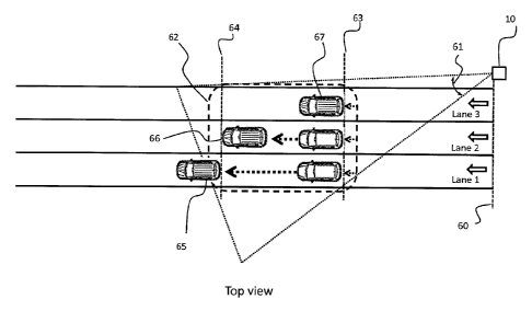
covering several lanes and several meters of depth and detects several
vehicles on
several lanes in a roadway.
[00110] The detection system can be configured with two trigger positions. The
first
trigger 63 is set in the first section of the detection zone and the second
trigger 64 is
set a few meters away, in this case close to the end of the detection zone. In
this
example, a first vehicle 65 was detected when entering the detection zone on
lane 1,
was tracked, was detected at the position of the first trigger 63, was
continuously
tracked and is now being detected at the position of the second trigger 64.
Information about its lane position, speed, etc., can be constantly sent or
can be sent
only when the vehicle reaches pre-established trigger positions. A second
vehicle 66
was detected when entering the detection zone on lane 2, was tracked, was
detected
at the position of the first trigger 63, and is continuously tracked until it
reaches the
position of the second trigger 64. A third vehicle 67 was detected when
entering the
detection zone on lane 3, was tracked, is detected at the position of the
first trigger
63, will continue to be tracked and will reach the position of the second
trigger 64.
[00111] The detection system has the capability to identify, track and send
information about multiple vehicles at the same time and its multiple receiver
channels greatly reduce the cosine effect for speed measurement.
[00112] The system can capture several snapshots using the 2DOR at different
levels of illumination using the 2DOE. Information about each vehicle
(date/hour of an
event, speed, position, photographs and identification based on Automatic
License
Plate Recognition) can be sent to the external controller. This is useful for
applications like traffic management (for vehicle detection, volume,
occupancy, speed
measurement and classification), speed enforcement, red light enforcement,
etc. The
system can be permanently or temporarily installed. It can even be a mobile
system,
for example a system installed on a vehicle.
- 22 -
CA 2998166 2018-03-14
WO 24113/128427 PCT/I132013/051667
[00113] An example of configuration for Red Light Enforcement is shown in FIG.
7.
The capability of the system to detect, track, determine the lane position,
measure the
speed and take photographs (or videos) for each vehicle several meters away
from
the stop bar has great value for this application. Red light enforcement
applications
require the detection of a vehicle entering an intersection when the traffic
light is at
the red state and the automatic capture of several images of the vehicle as it
crosses
the stop bar and runs the red light. The detection system needs to provide
evidence
that a violation occurred without ambiguity.
[00114] For most applications, detection rates should be high, for example of
the
order of 95 % and more (without occlusion), and false detections should occur
only
very rarely_ Images and information about the date and time of the infraction
will allow
the authorities to transmit a traffic infraction ticket. Identification of the
driver and/or
owner of the vehicle is generally made by the authorities using the
information from
the license plate of the vehicle. Since speed information is available, speed
infractions can also be detected when the traffic light is green. As will be
readily
understood, the detection system can also be used for other detection
applications
such as stop line crossing and railway crossing.
[00115] In FIG. 7, the detection system is installed on the side of the road
at an
example distance of 15 to 25 m from the stop bar 70. The detection and
tracking zone
zo 71 starts few
meters before the stop bar 70 and covers several meters after the bar,
allowing a large and deep zone for detecting and tracking any vehicle on
several
lanes (three lanes in that example), at different speeds (from 0 to more than
100 km/h), at a rate of up to ten vehicles detected per second. The detection
system
can take several images of a red light infraction including, for example, when
the
vehicle is located at a predetermined trigger distance, for example at first
trigger 72
when the back of the vehicle is close to the stop bar 70 and at second trigger
73
when the back of the vehicle is few meters away from the stop bar 70. Optional
- 23 -
CA 2 9981 66 2 0 1 8-0 3-1 4
WO 2013/128427 PCT/I132013/051667
detection of the lane position is useful when a right turn on red is allowed
at the
intersection.
[00116] Speed enforcement is another application that requires providing
evidence
that a speed violation occurred. The correlation between the detected speed
and the
actual vehicle guilty of the infraction needs to be trustworthy. Sufficient
information
should be provided to allow identification of the vehicle owner, using
information from
the license plate, for example. The capability of the detection system to
measure the
speed of several vehicles at the same time with high accuracy and to make the
association between each speed measurement and the specific identified vehicle
is
useful for traffic enforcement applications. This is made possible by, among
others,
the multiple FOV, the robustness and accuracy of the sensor and the capability
to
store several images of a violation.
[00117] The detector can store speed limit data (which can be different for
each
lane) and determine the occurrence of the infraction.
[00118] The detector can be mounted on a permanent installation or can also be
temporary, provided on a movable tripod for example. Detectors can also be
installed
at the entry and at the exit of a point-to-point enforcement system allowing
the
measurement of the average speed of a vehicle by determining the amount of
time it
takes to displace the vehicle between the two points. The position of each
vehicle
and its classification are also information that the detector can transmit to
the external
controller. In some countries, lane restriction can be determined for specific
vehicles,
such as trucks for example.
[00119] Moreover, the multipurpose traffic detection system can fulfill more
than one
application at a time. For example, the system used for traffic management
near an
intersection can also be used for red light enforcement at that intersection.
Methods for alignment and detection of the traffic detection system
- 24 -
CA 2998166 2018-03-14
WO 2013/128427 PCT/1132013/051067
[001201 A method that allows a rapid and simple alignment step for the
multipurpose
traffic detection system after it has been set in place is provided.
[00121] FIGS. 8A and B show examples images of a roadway captured by the
2DOR during the day_ The image is overlaid with the perimeters of a set of 16
contiguous detection zones of the 3DOR. In FIG. 8A, a vehicle present in the
first
lane 32 would be detected by several adjacent channels at a respective
detected
distance between 17.4 m to 17.6 m (see the numbers at the bottom of the
overlay). In
FIG. 8B, the vehicle is detected in the second lane 34 between 24.0 m to 24.4
m.
Note that the overall detection zone is wide enough to cover more than two
lanes. In
some situations depending on the context of the installation, some objects or
even
the ground can be detected by the system but can be filtered out and not be
considered as an object of interest.
[00122] FIG. 9A shows a photograph of a red light enforcement application
installation. Some channels detect echo back signals from the ground (see the
numbers at the bottom of the overlay) but the system is able to discriminate
them as
static objects. FIG. 9B is a graph showing a top view of the 3D 16 field of
view of a
road with 3 lanes. In a Cartesian coordinate system, if the detection system
represents the origin, the horizontal direction from left to right is taken as
the positive
x-axis and represents the width of the 3 lanes in meters, and the vertical
direction
from bottom to top is taken as the positive y-axis and represents the
longitudinal
distance from the sensor. To facilitation installation, the installation
software will
indicate the beginning and the end of the detection zone by showing a
detection line
as seen in FIG. 9B.
Multi-vehicle simultaneous detection and tracking for position determination,
speed
measurement and classification
[00123] FIG. 10 shows a top view of an example road facility equipped with a
multipurpose traffic detection system 10. The system 10 mounted on an existing
- 25 -
CA 2998166 2018-03-14
WO 2013/128427 PCT/IB2013/051667
traffic infrastructure is used to illuminate a detection zone 42. In this
example, the
mounting height is between 1 and 10 m with a distance from the road between 1
and
m. In FIG. 10, the vehicles 46 travel in lanes 43, 44 and 45 in a direction
indicated
by arrow A through the detection system illumination zone 42. The detection
system
5 10 is used for detecting information of the rear surface of vehicles 46
coming in the
illumination zone 42. The detection system 10 is based on IR LED illumination
source
with a multiple field-of-view detector.
[00124] In FIG. 11, the 16 fields of view 52 covering a section of the road
are
shown. In a Cartesian coordinate system, if the detection system represents
the
origin 49, the horizontal direction from left to right is taken as the
positive x-axis 50,
and the vertical direction from bottom to top is taken as the positive y-axis
51 then,
each 3D detection 53 gives the distance between an object and the sensor.
[00125] FIG. 12 shows the system in an example configuration with two trigger
lines
56 and 57 located at a distance from the sensor between 10 and 50 m, for
example.
The two trigger lines 56 and 57 are configured by the user. Blob 55
illustrates a
detectable vehicle rear. When the blob reaches the trigger line, the system
returns a
trigger message.
[00126] FIG. 13 and FIG. 14 show example data for vehicle tracking in the
context
of traffic light enforcement. Thanks to a projection of the field-of-view of
the detection
system on the real 2D image, the relationship between the top view (FIGS. 13B,
13D,
13F) and the scene (FIGS. 13A, 13C, 13E) is made apparent. The 3D detections
are
represented by dots in the top views. In this example, a small diamond in the
top
views shows the estimated position of the rear of each vehicle based on the 3D
detections. In this example, the small diamond represents the middle of the
rear of
the vehicle. The distance of detection is indicated under each detection
channel in
the scene image. The amplitude of the detection is also indicated below the
distance
of detection. On the top view, thin lines define the limits of the tracking
area and
dotted lines define two trigger lines configured by the user. When entering
this area, a
- 26 -
CA 2998166 2018-03-14
WO 2013/128427 PCT/I132013/051667
new vehicle is labeled with a unique identifier. In each frame, its estimated
position is
shown using a small diamond. As shown, the interactions between vehicle
detections
are managed by the tracking algorithm allowing distinguishing vehicles located
in the
detection area.
[00127] FIG. 15 shows the steps performed during the execution of an example
tracking algorithm. At step 80, the tracking algorithm selects the reliable
measurements located on the road. At step 81A, the generic Kalman Filter for
tracking a variable number of objects is used. At step 82, a road user
classification
based on geometric features is computed. Finally, step 83 sends to each frame,
a
message with position, speed, class and trigger if necessary for the vehicles
located
in the detection zone_
[00128] FIG. 16 shows the steps performed during the execution of the tracking
algorithm if the traffic light state 85 is known. Steps 80/800, 82 and 83 are
unchanged. However, step 81B is different because the additional information
allows
working in a space-based tracking joint.
[00129] The selection of relevant measures 80 is described in FIG. 17. At step
100
the tracking algorithm reads the available observations. At step 101, the
tracking
algorithm removes each detection that is not located on the road. Step 101 is
followed by step 102 where the tracking algorithm recognizes lines by a
feature-
based approach. Step 103 eliminates the points located on lines parallel to
the x-axis
50 with the aim of extracting the characteristics relating to the side(s) of
vehicles and
to keep only the objects having a "vehicle rear signature".
[00130] The estimation of a line based on the covariance matrix using polar
coordinate 102 is illustrated in FIG. 18. This estimation is based on feature
extraction.
The strength of the feature-based approach lies in its abstraction from data
type,
origin and amount. In this application, line segments will be considered as a
basic
primitive which later serves to identify and then remove the side of vehicles.
Feature
- 27 -
CA 2998166 2018-03-14
W02013/128427 PCT/182013/051667
extraction is divided into two sub-problems: (i) segmentation to determine
which data
points contribute to the line model, and (ii) fitting to give an answer as to
how these
points contribute.
[00131] The polar form is chosen to represent a line model:
[00132] x cos a y sin a = r
[00133] where -71" <a < it is the angle between the x axis and the normal of
the
line, r > 0 is the perpendicular distance of the line to the origin; (x, y) is
the Cartesian
coordinates of a point on the line. The covariance matrix of line parameters
is:
[00134] cov(r, a) =[0-7- am]
Crra cra
[00135] FIG. 19 shows a state diagram for the 3D real-time detection multi-
object
tracker. The core of the tracker 91A is based on a Kalman Filter in all
weather and
lighting conditions. The observation model 90 is illustrated in FIG. 21 which
presents
an example method to compute the vehicle position by weighting each 3D
observation according to its height amplitude. This method permits to improve
the
accuracy of the estimated position with respect to using only the x and y
Cartesian
positions.
[00136] Expression 301 computes the blob position as follows:
[00137] P
- blob = =17171
[00138] where nn is the intensity weight for the observation n, it E ...,N,
and N
is the number of observation grouped together. Step 301 is followed by
computing
the observation weight depending on the intensity at step 302.
- 28 -
RECTIFIED SHEET (RULE 91)
CA 2998166 2018-03-14
WO 2013/128427 PCT/182013/051667
[001391 The function 300 normalizes the weight irn according to the amplitude
An of
the observation Pn:
A't
[001401 Trn ¨
E An
[00141] The state evolution model 92 is represented by the classical model
called
speed constant. Kinematics model can be represented in a matrix form by:
[00142] pk+i F. Pk + G. Vk, Vk ¨N (0, Qk)
[00143] where Pk = (xcdõ, abs, yobs, ,robs.) is the target state vector, F
the transition
matrix which models the evolution of p Qk the covariance matrix of VA, and G
the
noise matrix which is modeled by acceleration.
_ AT2
AT 0 G 0
0 1 0 0 -
AT 0 n 1-17,2 0
[00144] F =
0 0 1 Lid 10 Cr 2
[00145] The equation observation can be written as:
[00146] Zk H. pk + Wk, Wk ¨N (0, Rk)
[00.147] Where Zk = (Xobsk , yob,k)t is the measurement vector, H the
measurement
sensitivity matrix, and Rk the covariance matrix of Wk
{1 0 0 0} 2 0 1
0 0 a 0 uobsx
[00148] H = Rk = 0 2
0 0 1 0 "obsy
0 0 0 0
[00149] The state space model 93A is based on probabilistic framework where
the
evolution model is supposed to be linear and the observation model is supposed
to
be Gaussian noise. In a 3D image, the system state encodes the information
- 29 -
RECTIFIED SHEET (RULE 91)
CA 2998166 2018-03-14
WO 2013/128427 PCT/IB2013/051667
observed in the scene, e.g. the number of vehicles and their characteristics
is
= (74 , In with N as the number of detected vehicles, where pf denotes the 2D
position of object N at iteration k, els,/ gives identification, age, lane and
the object
classification.
[00150] FIG. 20 shows a state diagram for 3D real-time detection multi-object
joint
tracker. The core of 91B is based on a Kalman Filter which addresses the issue
of
interacting targets, which cause occlusion issues. When an occlusion is
present, 3D
data alone can be unreliable, and is not sufficient to detect, at each frame,
the object
of interest. If the algorithm uses the traffic light state 85, occlusions can
be modeled
with a joint state space model 938. Tile multi-object joint tracker includes a
multi-
object interaction distance which is implemented by including an additional
interaction
factor in the vehicle position. The state space model 93B encodes the
observations
detected in the scene, e.g. the number of vehicles, the traffic light state
and the
interaction between the vehicles located in the same lane by concatenating
their
configurations into a single super-state vector such as: Xk = (0k, , 4)
with Ok
the size of state space at iteration k and x = (4,41) the state vector
associated
with the object N, where plicv denotes the 2D position of the object N at
iteration k, 111
gives identification, age, lane, class, traffic light state and the object
interaction.
100151] Before integrating measures into the filter, a selection is made by a
two-step
procedure shown in FIGS. 22 and 23 : first at step 400 validation gate, then
at step
401A/13 data association. The validation gate is the ellipsoid of size k
(dimension of
vector) defined such as:
[00152] 6t.5-1.79 y
[00153] where 19t = Zk ¨ Hp; is the innovation, S the covariance matrix of the
predicted value of the measurement vector and y is obtained from the chi-
square
tables for Atz degree of freedom. This threshold represents the probability
that the
(true) measurement will fall in the gate. Step 400 is followed by step 401A/B
which
- 30 -
RECTIFIED SHEET (RULE 91)
CA 2998166 2018-03-14
WO 2013/128427 PCT/I132013/051667
makes the matching between a blob and a hypothesis. Then, (i) consider all
entries
as new blobs; (ii) find the corresponding entries to each blob by considering
gating
intervals around the predicted position of each hypothesis, (iii) choose the
nearest
entry of each interval as the corresponding final observation of each blob. At
step
402, the tracking algorithm uses a track management module in order to change
the
number of hypothesis. This definition is: (i) if, considering the existing
assumption,
there occurs an observation that cannot be explained, the track management
module
proposes a new observation; (ii) if an assumption does not find any
observation after
500 ms, the track management module proposes to suppress the assumption. In
this
case, of course, an evolution model helps to guide state space exploration of
the
Kalman filter algorithm with a prediction of the state. Finally, step 403 uses
a Kalman
framework to estimate the final position of the vehicle.
[00154] In a 3D image, the system state encodes the information observed in
the
scene, the number of vehicles and their characteristics is Xk = (0k, Ai, , 41)
with Ok
the size of state space (number of detected vehicles) at iteration k and 4 =
(p;,v,
the state vector associated with object N, where pg denotes the 2D position of
object
N at iteration k, 411 gives identification, age, lane and the object
classification. Step 90
and 92 are unchanged.
[00155] FIG. 24 shows the steps performed during the execution of the
classification
algorithm. At step 500, the algorithm checks if a line is detected in the 3D
image. If a
line is detected, step 500 is followed by step 501 which computes vehicle
length.
Vehicle length is defined as the overall length of the vehicle (including
attached
trailers) from the front to the rear. in order to calculate the length, two
different
positions are used: X0 and X1.. X0 is given by the position of the first
detected line and
X1 is given by the trigger line 1 (for example). Once the speed has been
estimated,
the vehicle length I can be determined such as:
-31 -
RECTIFIED SHEET (RULE 91)
CA 2998166 2018-03-14
WO 2013/128427 PCT/1132013/051667
[00156] / Em] = s [m/S] * (X1 (t)Is] ¨ X0 (t) [s]) ¨ (Xi (x)[m] ¨ Xo (x)[mi) +
Seg[m} T H [In]
Where s is the vehicle speed, Sey is the length of the detected line and TH is
a
calibration threshold determined from a large dataset.
[00157] If the line is not detected at step 500, step 500 is followed by step
502 which
computes the vehicle height. The vehicle height is estimated during the entry
into the
sensor field of view. As shown in FIG. 26, for a known configuration of the
detection
system, there is a direct geometric relationship between the height of a
vehicle 601
and the detection distance 600. The accuracy 602 is dependent on the half-size
of
the vertical FOV angle 603. Height measurement is validated if the accuracy is
lower
than a threshold.
[00158] Finally, step 502 is followed by step 503 which computes the vehicle
width.
Over the vehicle blob, let (ye, x) be leftmost pixel and (yr, x) be the
rightmost pixel in
the vehicle blob for a given x. Then the width w of the object is determined
from the
following formula:
[00159] w = ly, yef
[00160] FIGS. 25A, 25B and 250 shows a result of vehicle classification based
on
the classification algorithm. For example, in FIG. 25A, the classification
result is a
heavy vehicle; in FIG. 25B, it is a four-wheeled lightweight vehicle and in
FIG. 25C, it
is a two-wheeled lightweight vehicle. The information from the detection
system is
flexible and can be adapted to different schemes of classification. FIG. 25
illustrates
graphically the basic elements of the concept of an object-box approach which
is
detailed below and in FIG 27 and FIG. 28.
[00161] The object-box approach is mainly intended for vehicles because this
approach uses the vehicle geometry in a LEDDAR image. The vehicles are
represented by a 30 rectangular box of detected length, width and height. The
3D
size of the rectangular box will vary depending on the detections in the FOV.
FIGS. 27A, 27B, 270 and 27D show top view frames of a vehicle detected by the
- 32 -
RECTIFIED SHEET (RULE 91)
CA 2998166 2018-03-14
WO 2013/128427 PCT/1132013/051667
LEDDAR sensor. FIGS. 28A, 28B, 28C and 28D show corresponding side view
frames of the vehicle of FIG. 27,
[00162] FIGS. 27A, 27B, 27C, 27D and FIGS. 28A, 283, 280, 28D show the
changing 3D size of the rectangle 701 for four example positions of a vehicle
702 in
the 3D sensor FOV 703. When a vehicle 702 enters the 3D sensor FOV 703, two
detections are made on the side of the vehicle (see FIG. 27A) and one
detection is
made for the top of the vehicle (see FIG. 28A). The 3D rectangle is
initialized with a
length equal to 4 m, a width of 1.5 m and a height 0 fini given by
[00163] OH, II,¨ dist * tan(0)
[00164] Where 113 is the sensor height 704, dist is the distance of the
detected
vehicle and C is sensor pitch.
[00165] FIG. 278 and FIG. 288 represent detections when the vehicle is three-
fourths of the way in the detection FOV. Eight side detections are apparent on
FIG. 278 and one top detection is apparent on FIG. 2813. The dimensions of the
3D
rectangle are calculated as follows:
[00166] The width is not yet adjusted because the vehicle back is not yet
detected.
[00167] 01(k) = max(L2 ¨ L1, 0 t(k ¨ 1))
[00168] Oh(k) = 771aX(Olim ,Oh (k ¨ 1))
[00169] Where the points of a segment are clockwise angle sorted so L2 is the
point
with the smallest angle and L1 is the segment-point with the largest angle.
0/(k)and
Oh(k) are respectively the current length and height value at time k.
[00170] FIG. 270 and FIG. 28C represent detections when the back of the
vehicle
begins to enter in the detection FOV. Eight side detections and two rear
detections
- 33 -
RECTIFIED SHEET (RULE 91)
-CA 2998166 2018-03-14
WO 2013/128427 PCT/IB2013/051667
are apparent on FIG. 27C while one detection is apparent on FIG. 28C. The
dimensions of the 30 rectangle are calculated as follows:
[00171] 01(k) = max(L2 , 01(k ¨ 1))
[00172] Oh(k) = max(OHn , Oh(k ¨ 1))
[00173] Ow(k) = max(L4 ¨ L3 , Ow(k - 1))
[00174] As for the horizontal segment representing the side of the vehicle,
the points
of the vertical segment representing the rear and/or the top of the vehicle
are
clockwise angle sorted, so L4 is the point with the smallest angle and L3 is
the
segment-point with the largest angle.01(k), Oh(k)and Ow(k) are respectively
the
io current length, height and width value at time k.
[00175] FIG. 270 and FIG. 28D represent detections when the back of the
vehicle is
fully in the detection FOV. Six side detections and four rear detections are
apparent
on FIG. 27D while one detection is apparent on FIG. 28D. The width Oim
dimension is
calculated as follows:
[00176] Otn,(k) = a* (L4 ¨ L3 ) (1 ¨ a) * Oim(k ¨ 1)
[00177] Where 01,,(k) is the current width at time k and a is the filtering
rate.
[00178] The size of the vehicle can then be determined fully.
[00179] The segmentation algorithm 800 based on a 3D bounding box for
selection
of the relevant measures is illustrated in FIG, 29, The first three steps are
identical to
that of FIG. 17. If step 120 finds horizontal lines, then step 120 is followed
by step
121. As explained above, the points of a segment are clockwise angle sorted
withL2,
the smallest angle and L1 the largest angle. This segment length is given byL2
¨ L1.
Otherwise, the next step 123 initializes the 3D bounding box with a default
vehicle
length. Step 121 is followed by step 122 which considers that two segments
have a
- 34 -
RECTIFIED SHEET (RULE 91)
CA 2998166 2018-03-14
WO 2013/128427 PCT/M2013/051667
common corner if there is a point of intersection Pi between the two segments
with
1Pi ¨ L11 and 1Pi ¨ L41 less than a distance threshold. If no corner is found,
step 123
initializes the 3D bounding box with default values. Otherwise, step 124
computes the
3D bounding box dimensions from equations presented above with respect to
FIG. 27C.
[00180] It is of interest to derive minimum variance bounds on estimation
errors to
have an idea of the maximum knowledge on the speed measurement that can be
expected and to assess the quality of the results of the proposed algorithms
compared with the bounds. In time-invariant statistical models, a commonly
used
lower bound is the Cramer-Rao Lower Bound (CRLB), given by the inverse of the
Fisher information matrix. The PCRB can be used for estimating kinematic
characteristics of the target.
[00181] A simulation was done according to the scenario shown in FIG. 30. The
vehicle 130 is moving at a speed of 60 m/s along a straight line in lane 3.
The PCRB
was applied. As shown in FIG. 31, the tracking algorithm converges at point
903 at
about CT;cp = 0.48 km/h after 80 samples. From point 900, it is apparent that
after 16
samples, 0-kp, <3 km/h, from point 901 that after 28 samples, o-K"F < 1.5 km/h
and
from point 902 that after 39 samples,o-kF <1 km/h. Experimental tests
confirmed the
utility and viability of this approach.
Image processing and applications
[00182] The multipurpose traffic detection system uses a high-resolution image
sensor or more than one image sensor with lower resolution. In the latter
case, the
control and processing unit has to process an image stitching by combining
multiple
images with different FOVs with some overlapping sections in order to produce
a
high-resolution image. Normally during the calibration process, the system can
determine exact overlaps between images sensors and produce seamless results
by
controlling and synchronizing the integration time of each image sensor and
the
- 35 -
RECTIFIED SHEET (RULE 91)
CA 2998166 2018-03-14
WO 2013/128427
PCT./1132013/051667
illumination timing and analyzing overlap sections. Infrared and color image
sensors
can be used with optical filters.
[00183] At night, a visible light is required to enhance the color of the
image. A NIR
flash is not visible to the human eye and does not blind drivers, so it can be
used at
any time of the day and night.
[00184] Image sensors can use electronic shutters (global or rolling) or
mechanical
shutters. In the case of rolling shutters, compensation for the distortions of
fast-
moving objects (skew effect) can be processed based on the information of the
position and the speed of the vehicle. Other controls of the image sensor like
Gamma
and gain control can be used to improve the quality of the image in different
contexts
of illumination.
[00185] FIG 32A is a photograph showing an example snapshot taken by a
5 Mpixeis image sensor during the day. Vehicles are at a distance of
approximately
25 m and the FOV at that distance covers approximately 9 m (almost equivalent
to
3 lanes). FIGS. 32B, 320 and 32D show the quality of the image and resolution
of
FIG. 32A by zooming in on the three license plates.
[00186] FIG, 33A is a photograph showing an example snapshot taken by the
image
sensor at night without any light. This image is completely dark. FIG. 33B
shows the
same scene with infrared light. Two vehicles can be seen but the license
plates are
not readable even when zooming in as seen in FIG. 33C. The license plate acts
as a
retro-reflector and saturates the image sensing, FIGS. 34A and 34B use the
same
lighting with a lower integration time. The vehicle is less clear but the
image shows
some part of the license plate becoming less saturated. FIGS. 340 and 34D
decrease
a little more the integration time and produce a readable license plate.
[00187] One way to get a visible license plate at night and an image of the
vehicle is
to process several snapshots with different integration times (Ti). For
example, when
the 3D detection confirms the position of a vehicle in the detection zone, a
sequence
- 36 -
RECTIFIED SHEET (RULE 91)
CA 2998166 2018-03-14
WO 2013/128427 PCT/IB2013/051667
of acquisition of several snapshots (ex.: 4 snapshots with Ti1=50 ..is,
Ti2=100 ps,
T13=250 ps and Ti4=500 ps), each snapshot taken at a certain frame rate (ex.:
each
50 ms), will permit to get the information on a specific vehicle: information
from the
3D sensor, a readable license plate of the tracked vehicle and an image from
the
context including the photo of the vehicle. lithe system captures 4 images
during
150 ms, a vehicle at 150 km/h would travel during 6.25 m (one snapshot every
1.5 m).
poi 881 To enhance the quality of the image, high dynamic range (HDR) imaging
techniques can be used to improve the dynamic range between the lightest and
darkest areas of an image. HDR notably compensates for loss of information by
a
saturated section by taking multiple pictures at different integration times
and using
stitching process to make a better quality image.
[00109] The system can use Automatic License Plate Recognition (ALPR), based
on Optical Character Recognition (OCR) technology, to identify vehicle license
plates.
This information of the vehicle identification and measurements is digitally
transmitted
to the external controller or by the network to back-office servers, which
process the
information and can traffic violation alerts.
[00190] The multipurpose traffic detection system can be used day or night, in
good
or bad weather condition, and also offers the possibility of providing weather
information like the presence of fog or snowing conditions. Fog and snow have
an
impact on the reflection of the radiated light pulses of the protective
window. In the
presence of fog, the peak amplitude of the first pulse exhibits sizable time
fluctuations, by a factor that may reach 2 to 3 when compared to its mean peak
amplitude level. Likewise, the width of the first pulse also shows time
fluctuations
during these adverse weather conditions, but with a reduced factor, for
example, by
about 10 to 50 %. During snow falls, the peak amplitude of the first pulse
visible in the
waveforms generally shows faster time fluctuations while the fluctuations of
the pulse
width are less intense. Finally, it can be noted that a long-lasting change in
the peak
- 37 -
RECTIFIED SHEET (RULE 91)
CA 2998166 2018-03-14
WO 2013/128427 PCl/1B2013/051667
amplitude of the first pulse can be simply due to the presence of dirt or snow
deposited on the exterior surface of the protective window.
[00191] FIG. 35 shows an example image taken with infrared illumination with
the
overlay (dashed lines) representing the perimeter of the 16 contiguous
detection
zones of the 3DOR. Apparent on FIG. 35 are high intensity spots 140 coming
from a
section of the vehicle having a high retro-reflectivity characteristic. Such
sections
having a high retro-reflectivity characteristic include the license plate,
retro-reflectors
installed one the car and lighting modules that can include retro-reflectors.
An object
with retro-reflectivity characteristic reflects light back to its source with
minimum
scattering. The return signal can be as much as 100 times stronger than a
signal
coming from a surface with Lambertian reflectance. This retro-reflectivity
characteristic has the same kind of impact on the 3DOR. Each 3D channel
detecting
a retro-reflector at a certain distance in its FOV will acquire a waveform
with high
peak amplitude at the distance of the retro-reflector. The numbers at the
bottom of
the overlay (in dashed lines) represent the distance measured by the
multipurpose
traffic detection system in each channel which contains a high peak in its
waveform.
Then, with a good -image registration between the 2D image sensor and the 3D
sensor, the 2D information (spot with high intensity) can be correlated with
the 3D
information (high amplitude at a certain distance). This link between 2D
images and
3D detection ensures a match between the identification data based on reading
license plates and measurements of position and velocity from the 3D sensor.
[00192] The license plate identification process can also be used as a second
alternative to determine the speed of the vehicle with lower accuracy but
useful as a
validation or confirmation. By analyzing the size of the license plate and/or
character
on successive images, the progression of the vehicle in the detection zone can
be
estimated and used to confirm the measured displacement.
- 38 -
RECTIFIED SHEET (RULE 91)
CA 2998166 2018-03-14
WO 2013/128427 PCT/132013/051667
The embodiments described above are intended to be exemplary only. The
scope of the invention is therefore intended to be limited solely by the
appended
claims.
- 39 -
RECTIFIED SHEET (RULE 91)
CA 2998166 2018-03-14