Note : Les descriptions sont présentées dans la langue officielle dans laquelle elles ont été soumises.
13192~4
WH-778~-89 - 1 -
PROCESS FOR THE MONITORING AND/OR FEEDsACK CONTROL
OF THE DAMPING IN AN OFFSET PRINTING PRESS
The invention relates to a process for the monitoring of
the damping in an offset printing press. In the offset
process, a shortage of damping solution results in
streaks and irregularly distributed ink dots at those
places that would be free of ink if the quantity of
dàmping solution were correct. Such ink deposits that
occur due to a shortage of damping solution appear, as
there starts to be a shortage of damping solution, first
of all behind (as viewed in the paper-running direction)
areas with high area coverage. AS the shortage of
damping solution further lncreases, the area of the ink
deposits becomes greater until this so-called scumming
extends also to other, otherwise non-printed areas.
The beginning of scumming is visually detectable only
with appropriate magnification, for example with a
magnifying glass. However, scumming rarely occurs
simultaneously across the entire width of the sheet or
web. For this reason, visual inspection by means of a
magnifying glass must extend across the entire width and
therefore requires a considerable expenditure of time
and concentration on the part of the printer. There is
also the fact that too high a level of damping, which
provides a large safety margin with respect to the
scu~ning limit, results in reduced-contrast and less
sharp prints. In the interests of a good quality of the
X
WH-7784-89 - 2 - 1319 2 ~ 4
printed products, therefore, efforts are made to print
as close as possible to the scumming limit.
In known designs for the monitoring and/or feedback
control of ~he quantity of damping solution, the
quantity of damping solution in the ink or on the
printing plate is determined in the printing unit by
either direct or indirect measuring processes. The
known processes, however, exhibit various disadvantages
and have, therefore, not proven themselves in practice.
Thus, for example, the damping-solution content in hlack
printing ink is not measurable with infrared processes.
Furthermore, damping-solution measurements on the plate
are greatly dependent on the reflective behaviour of the
surface of the plate. The assignment of the measured
values to the water-film thickness is, therefore,
different from one type of plate to the next and is
additionally dependent on the direction of rolling.
The object of the invention is to disclose a process for
the monitoring and/or Eeedback control of the damping in
an offset printing press in which, uninfluenced by other
parameters, a shortage of damping solution can be
detected, displayed and/or corrected.
The process according to the invention is characteri~ed
in that non-printed areas in the region of edges of
specified inked areas are scanned with the aid of an
opto-electric receiver and in that the signals generated
by such scanning are evaluated. Preferably scanned are
non-printed areas that are situated at rear (as viewed
in the printing direction) edges of the inked areas. It
is also possible, however, within the scope of the
invention for other edge regions of inked areas to be
scanned.
X
WH-7784-89 - 3 - 131 9 2 9~
As specified inked areas, it is possible preferably to
use measuring fields of a print-check strip, said
measuring fields representing an individual colour or a
printing unit. It is also possible, however, to use
S other suitable inked areas that are located anyway
within the printed image.
The specif.ied inked areas may be full-tone fields or
half-tone fields with high area coverage, but always
only ink fields of one single colour - i.e. not several
colours printed one on top of the other. A further
development of the process according to the invention,
said further development permitting visual monitoring,
consists in that the respectively scanned areas are
represented in enlarged form on a screen.
Another further development of the invention consists in
that the signals generated by the scanning of the areas
situated behind the edges of the specified inked areas
are compared with reference values and in that,
depending on the result of the comparison, a damping-
solution-shortage signal is derived, said signal
identifying too low a level of damping. It is of
particu].ar advantage in this connection that the
reference value lies between the brightness of the non-
printed area and the brightness of the inked area.
The signals may first of all be compared with a
reference value, said reference value lying between the
brightness of the non-printed area and the brightness of
the inked area. Thereafter, the area coverage of the
signals that overstep or understep the reference value
is calculated with respect to the respectively scanned
area. This is done preferably by the counting of image
elements. A damping-solution-shortage signal is derived
if the area coverage oversteps a specified level.
X
WH-7784-89 - 4 _ 1319 2 3 4
This further development of the invention also permlts
the automatic monitoring and/or control of the damping.
The scanning may be performed preferably on a printed
sheet. With the process according to the invention,
scanning on the rubber blanket or on the clamped
printing plate is not impossible.
A process according to the invention, in which, in
addition to monitoring, feedback control of the damping
is also provided, is characterized in that the feedback
control of the damping is performed as a function of the
evaluation of the signals generated by the scanning.
In an advantageous embodiment of the further development
of the invention, it is provided that the damping is
increased if the damping-solution-shortage signal occurs
and is gradually reduced if no damping-solution-shortage
signal occurs.
In another further development, in addition, the inked
areas are scanned and a damping-solution-excess signal
is derived from the signal generated by the scanning of
the inked areas. For this purpose, the signals
generated by the scanning of the inked areas can be
supplied to an image-processing system. The resulting
damping-solution-excess signal can be used together with
the damping-so]ution-shortage signal in order to control
the damping.
The measures enumerated in the further subclaims permi~
further advantageous developments of and improvements to
advantageous arrangements for the implementation of the
process according to the invention.
X
WH-7784-89 - 5 - 131929~
Specimen embodiments of the invention are explained in
greater detail in the following description and are
represented in the drawings with reference to several
Figures, in which:
Fig. 1 shows a part of a printed sheet with a print-
check strip;
Fig. 2 and Fig. 3 show a known apparatus for the
evaluation of a printed ink-measuring strip with
additionally integrated damping-measuring head;
Fig. 4 shows a schematic representation of a measuring
head suitable for the process according to the
invention as well as of a circuit arrangement
for the implementation of the process according
to the invention;
Fig. 5 shows timing diagrams of some signals occurring
with the circuit arrangement according to
Fig. 4;
Fig. 6 shows an embodiment of a part of a damping
measuring head and
Fig. 7 shows a further circuit arrangement for the
implementation of the process according to the
invention.
Identical parts in the figures are provided with
identical reference characters.
The detail of a printed sheet 5 shown in Fig. 1 contains
a print-check strip MS with several measuring fields MF.
From the various measuring fields MF, shown in Fig. 1
among other things are full-tone fields of the colours
X
WH--778a~-89 - 6 - ~L 31~ 2 ~ 4
B = black, C = cyan, M = magenta, Y = yellow as well as
of a fifth and sixth colour. Shown by way of example as
half-tone fields with an ink coverage of 70 % to 90% are
fields of colours s and C. Since, as there starts to be
a shortage of damping solution, scumming begins
initially, for example in black, behind the full-tone
field s, greater scumming occurs in the example shown,
while the scumming is less pronounced in the half-tone
field B.
n the process according to the invention, the area
indicated by the broken line in Fig. 1 is scanned.
Scanning is performed line by line, with the lines lying
parallel to the printing direction and a sensor,
described in greater detail in conjunction with Fig. 4,
being used for scanning in said direction. For the sake
of clarity, Fig. 1 shows only a few lines Z. The
scanning transverse to the printing direction is
performed preferably with a known device, which is shown
in Fig. 2 and in Fig. 3.
Instead of a line sensor, it is also possible to use an
area sensor, which, for example in one position each
time, scans an area F, which is assigned to a specific
measuring area.
The device illustrated in Fig. 2 contains a measuring
table 1 and on said measuring table 1 a measuring bridge
2 with a measuring carriage 3, four clamping blocks 4
for securing a printed sheet 5 to be measured, an
electronics unit 6 and a personal computer 7. The top
layer is a layer of sheet steel, which allows the
printed sheet 5 to be secured by means of magnets or
similar. The personal computer 7 with integrated screen
terminal is rotatably mounted on the table. The
~r
~192~4
WH-7784-89 - 7 -
measuring carriage 3, the electronics unit 6 and the
personal computer 7 are connected via leads (not shown).
The electronics unit 6 contains a microprocessor system
and interfaces for the processing of the measuring- and
control signals supplied to it and produced by it. The
microprocessor system in the electronics unit cooperates
with the personal computer 7 in so-called master-slave
mode, with the personal computer performing the
monitoring function an evaluating the measured and
inputted data, while the system in the electronics unit
is responsible for execution of the measurements and of
the movements of the measuring carriage.
The measuring strip, i.e. the sequence of measuring-
field types, colours, area coverages etc. as well as the
distances between them, is known to the system by means
oE a once-only input. Consequently, measured values
need be transferred to the system only at certain
positions.
Fig. 3 shows an enlargement of the measuring bridge 2.
The latter contains two vertical side parts 11 and 12,
which support the remaining parts of the bridge, as well
as two outer casings 13 and 14, which extend over the
space between the two side parts and which are swivel-
mounted on the latter so that they may be hinged apart
into the positions illustrated in Fig. 3, thus providing
access to the inner parts of the measuring bridge. The
two side parts 11 and 12 are connected to each other by
a guide shaft 15 and a connecting rod 16 (only partially
shown).
The measuring carriage, referred to in its entirety as
3, is movable backwards and forwards on the guide shaft
15 and may also be swivelled about the shaft. The
X
WH-7784-89 - 8 - 1319 2 9 ~
measuring carriage 3 consists of a guide block 17
provided with two spherical bushes and of two measuring
heads 18 and 19 fixed to said guide block 17 as well as
of a guiding or holding-down plate 20, angled upwards at
both sides. On its lower side, the measuring carriage
is provided with rollers (not illustrated). During
operation, the measuring carrlage rests on the printed
sheet 5 that is to be measured, with the result that the
distance between the measuring heads 18 and 19 and the
individual fields MF of the measuring strip MS on the
printed sheet 5 is always constant. The measuring head
19 is basically of the type described in US-PS 4,078,858
and measures three colour channels simultaneously. The
measuring head 18 is used for implementing the process
according to the invention and is described in greater
detail with reference to Fig. 4.
Provided for the driving of the measuring carriage 3 is
a toothed belt 23, which is passed over two rollers 24
and 25 - each rotatably supported on one of the side
parts 11 and 12 - and to the lower side of which the
guide block 17 is fixed. The left-hand roller 25 in
Fig. 3 is driven by a stepper motor 27 via a toothed-
belt reduction-gear unit 26 (indicated only by a broken
line). The other roller 24 is supported in a freely
rotatable manner in a clamping device 28. The stepper
motor 27 and the gear unit 26 are designed such that the
toothed belt 23 and with it the measuring carriage 3 is
moved forward by 0.1 mm per complete motor step.
Disposed in the rear outer casing 13 is a guide section
connecting the measuring carriage 3 to the electronics
unit 6. Further disposed at the side parts 11 and 12
are quick-release locks (indicated by blocks 30) for the
fixing of the two outer casings 13 and 14 in their
hinged-up closed positions, as well as a fork-type light
X
~H-7784-89 - 9 - 1 31 .~ 2 9 ~
barrier 31, which interacts with a sheet-metal strip or
similar (not shown) on the guide bloc~ 17 or measuring
carriage 3 in such a manner that the measuring carriage
is automatically halted if it comes within a defined
minimum distance from one or other of the side parts,
e.g. owing to a control error.
Fixed in the front outer casing 14 is a mount 32, U-
shaped in cross-section, in which are disposed five
marking lamps, evenly distributed along the length of
the measuring bridge. ~hese lamps each consist of a
light source in the form of a so-called marker lamp (not
visible in Fig. 3) in the upper leg of the mount and of
a projection lens system 33 in the lower mount leg, and
produce on the printed sheet 5 five bars of marking
light, approximately 20 mm in length and arranged in a
line. The bars of light are used for the alignment of
the printed sheet 5 in such a manner that the measuring
strip MS is brought to lie precisely below the path of
motion of the two measuring heads 18 and 19.
Provided, finally, on the upper side of the front casing
14 is also an operating rocker 35 by means of which the
measuring carriage 3 may be moved under manual control
along the measuring strip MS into the desired measuring
position.
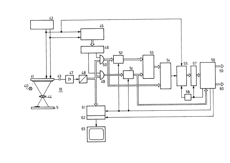
In the specimen embodiment shown in Fig. 4, scanning is
performed with a charge-coupled line sensor (CCD line)
41. As already mentioned, it is also possible to use
area sensors, i.e. video cameras with pickup tubes or
semiconductor pickup elements.
Line sensors are obtainable in different versions and
comprise, for example, 1,024 light-sensitive elements,
whose charges, dependent on the respective exposure, are
WH-7784-89 - 10 - ~ 31 ~29~
transmitted to an output register through application of
a pulse H (Fig. 5a) and are then read out serially from
the output register by clock pulses T. The pulses T and
H are derived in a clock generator 42. A video signal V
representing the brightness distribution on the line
sensor is then available at the output 43.
With the aid of an objective 44, one line at a time of
the area to be scanned on the printed sheet 5 is imaged
on the line sensor. This imaging includes some of the
measuring area as well as some of the non-printed part
of the printed sheet 5 lying behind the measuring area
MF. An illumination apparatus 40 serves for the purpose
of illumination.
Fig. 5b) shows an example of a video signal that is
present at 43, with the solid-line curve corresponding
to a line in which no scumming is detectable. Incipient
scumming, such as in the half-tone measuring field s
(Fig. 1), leads to dips in the video signal of the kind
shown by the broken line in Fig. 5b). Between times tO
and tl, the video signal represents the measuring area,
and between tl and t2, the video signal represents the
adjacent non-printed area.
The evaluation of the video signal may be effected in
various ways. A simple visual evaluation may be
performed by the enlarged representation of the video
signal on a monitor 62. sasically, various methods are
available for metrological evaluation of video signals.
A particularly simple method consists, for example, in
supplying the relevant time section of the video signal
via a gate circuit to a threshold-value circuit and, if
the threshold value is understepped, in emitting a
suitable signal. Evaluation may, however, also be
performed by complex methods, with it being possible to
X
WH-7784-8~ 13~29~
use analogue and digital circuits as well as computer
systems. In the arrangement shown in Fig. 4, the
processing steps that lead to a multi-digit digital
signal dependent on the degree of scumming are performed
with digital circuits. A microprocessor system 56 is
provided for further processing and for higher-ranking
control of the measuring process.
Since each line covers a period of time tO to tl, during
which the measuring field is scanned, and another period
of time tl to t2, which corresponds to the scanning of
the non-printed area behind the measuring field, the
pulses I1 and I2 shown in Fig. 5c) and 5d) are generated
in order to separate these signal components. For this
purpose, the clock pulse is supplied by the clock
generator 42 to a counter 45, which is reset by the
pulse H at the beginning of each line. The pulses Il
and I2 are derived from the count in a logic circuit 46
by appropriate combination of the individual digits of
the counter.
From the output 43 of the line sensor 41, the video
signal V passes via an amplifier 47 to the input of an
analogue/digital converter 48. The video signal is
available at the output of the analogue/digital
converter 48 in the form of a, for example, 8-bit-wide
digital signal DV and can therefore be further processed
in the following by digital circuits. An AND circuit 49
passes on the video signal DVMF obtained by the partial
scanning of the measuring field MF, while the AND
circuit 50 passes on that part DVT of the video signal
that represents the non-printed part of the printed
sheet.
In the following circuits 51, 52, the digital video
signals DVMF and DVT are each averaged with respect to
~ ' .
WH-7784-89 - 12 - 1319 2 9 4
time over the first lines produced in the scanning of
each measuring field MF (signals Sl and S2).
Subsequently, the two averages are, in turn, averaged in
a circuit 53, to form, for example, the arithmetic mean.
Thus, a threshold value S3 has been derived, which is
represented as the dash-dotted line in Fig. 5b). This
threshold value thus adapts to the brightness of the
measuring field M~ and to the brightness of the non-
printed part of the printed sheet 5. The signal Sl,
which corresponds to the mean brightness of the non-
printed sheet, may be derived in an adjacent non-printed
area of the sheet where there is certain to be no
scumming and can be stored until the scanning of the
non-printed area, which, however, may possibly be
affected by scumming.
The threshold value S3 as well as the digital video
signal DVT are supplied to a comparator, the output
signal of which is dependent on whether the video signal
understeps the threshold value S3 within the second
period of time tl to t2. This signal (Fi.g. 5a), could
in fact be used already as a damping-solution-shortage
signal, with, however, even the smallest errors in the
printed material triggering a false alarm. In the
circuit according to Fig. 4, therefore, it is provided
that the output signal of the comparator 54 enables or
disables a counter 55. The clock pulses T are supplied
to the clock input CLK of the counter. After the
printed area situated behind it, the contents of the
counter 55 are loaded into a register 57 and, shortly
thereafter, the counter 55 is reset. For this purpose,
the microprocessor system 56 supplies a load pulse to
the register 57 and, via a time-delay circuit 58, to the
reset input of the counter 55.
X
WH-7784-89 13 - 1 3 ~ ~ 2 9 ~
The counting of clock pulses during the length of time
during which the video signal v or DV understeps the
threshold S3 provides a measure of the area affected by
scumming. This measure may be evaluated in the
microprocessor system 56 in accordance with practical
requirements. Thus, for example, in the case of very
small area coverage, it may be decided that there is not
yet any scumming, and the area extending beyond it may
be used as a measure of the degree of scumming.
According to this information, further units, such as a
digital display device or actuators for the quantity of
damping solution, may be energized via outputs 59, 60 of
the microprocessor system 56.
During the scanning of each measuring field MF and of
the non-printed area behind it, the digital video
signals are written to a memory 61. If scumming occurs
in this measuring field, the microprocessor system 56,
by means of a signal S4, activates a read-out part 62 of
the memory, which reads out the stored signals from the
memory 61 and supplies them to a monitor 63. The read-
out process takes place repeatedly in order to obtain a
continuous display. The monitor 63, therefore, displays
the measuring area and the associated part of the non-
printed area only if there is scumming. In thisconnection, the threshold for display on the monitor may
be set relatively low, so that, even in the case of
incipient scumming, the printer is able to judge whether
action should be taken. During the remainder of the
time, the printer is not distracted by displays on the
monitor 63.
For automatic control of damping, the microprocessor
system 56 may contain a suitable program, which supplies
more damping solution if scumming occurs. Depending on
the embodiment of the process according to the
X
WH-7784-89 - 1~ - 1319 2 9 4
invention, there may be a once-only increase in the
supply of damping solution depending on the extent to
which scumming occurs (output of counter 55). It is
possible, however, after such an increase, for there
also to be a gradual, step-by-step reduction until
scumming occurs again. The quality of the printed
product is virtually unaffected by this ~exploratory~
overstepping of the scumming limit, because the process
according to the invention detects even the slightest
scumming - particularly if scanning takes place at a
point that is particularly critical with regard to
scumming (black full-tone area).
In order, according to a further development of the
process according to the invention, also to be able to
detect an excess of damping solution, the signal S2,
which represents the mean brightness of the scanned part
of a measuring field, is supplied to the microprocessor
system. This is because the coverage, particularly of
full-tone fields, deteriorates if there is an excess of
damping solution. If the setpoint value for a measuring
field has been stored in the microprocessor system, it
is possible to conclude from a deviation in the
brightness of a full-tone field that there is an excess
of damping solution. The result can be incorporated
into the automatic damping-solution control system.
In order to detect an excess of damping solution, it is
also possible to use an image-processing system. The
coverage, particularly of full-tone fields, deteriorates
noticeably if there is too much damping solution.
Through comparison with a perfect image or its area
coverage (one-hundred-percent coverage is not possible
because of the surface roughness of the stock), an
image-processing system is able to detect and to display
deviations and/or to derive control signals in
X
WH-7784-89 - 15 - ~ 31 9 2 9 ~
accordance with stored algorithms. Since clear
underinking can also cause a deterioration in coverage,
it is first of all detected through comparison of the
measured values for the inking of various or of all
zones whether there is underinking or an excess of
damping solution. An access of damping solution occurs
first of all in inking zones with low inking, since the
supply of damping solution is not controlled zonally. A
measure of the zonal area coverage and thus of the level
of inking is the inking-zone opening, the value of which
is known to the computer of the inking-control
apparatus. This value is used in the logic operations.
If, for example, the full tones of zones with low
inking-zone opening are poorly covered and less inked
than the full tones of zones with a larger opening, then
there is in this case an excess of damping solution.
At each transition between two measuring fields, the
microprocessor system 56, which also controls the
movement of the measuring head 19 in a manner not shown,
supplies a pulse I3 to the circuits Sl, S2 and to the
memory 61.
Fig. 6 shows schematically a measuring head with a line
sensor 41 onto which the original 5 that is to be
scanned is imaged with the aid of an objective 44. In
addition, an illumination apparatus 40 is provided. In
order to obtain averaging transverse to the direction of
the line sensor 41, the latter is provided with a
cylindrical lens 65. Thus, subsequent electrical
integration transverse to the line direction can be
omitted.
~7hereas, in the circuit arrangement according to Fig. 4,
the video signal is evaluated with a specially designed
circuit and the size of the area affected by scumming is
X
WH-7784-89 - 16 - 131~294
passed on to a mlcroprocessor system, in the circuit
arrangement according to Fig. 7, the entire evaluation
is performed by a microprocessor.
The scanning of an edge of a full-tone area MF over a
measuring area G is effected with the aid of a sensor
71. The signal produced by the sensor 71 is supplied
via an analogue/digital converter 72 to an input of the
microprocessor 73, which is connected to a display
apparatus 74 and, in addition, can be connected via an
output 75 to actuators for the control of the damping in
a printing press.
with the aid of a suitable program, the microprocessor
73 evaluates the digital video signals in an
advantageous manner, with it being possible to provide
steps similar to those in the circuit arrangement
according to Fig. 4.
X