Note : Les descriptions sont présentées dans la langue officielle dans laquelle elles ont été soumises.
CA 02711210 2010-07-26
Bipolar plate and method for its production
The present invention relates to a bipolar plate as well as to a method for
its production.
The bipolar plate according to the invention can be used in an electrochemical
system, for
example in a fuel cell system or in an electrolyser. Several types of
electrochemical systems
are known which make use of a stack of electrochemical cells with a layering
of a multitude
of electrochemical cells, which are each separated by bipolar plates. The
bipolar plates have
several functions:
- Electrical contacting of the electrodes of the individual electrochemical
cells and
conducting of electric current to the adjacent cells (serial connection of the
cells);
- Supplying media or reactants such as e.g. water or gases to the cells and
removal of
the reaction gases produced in the cell via a corresponding distribution
structure, the
so called flow field;
- Transport of the heat produced in the electrochemical cells; and
- Sealing of the different kinds of media and cooling channels of the flow
field relative
to each other and to the outside.
For the intended application at large industrial scale, it is of great
importance to be able to
produce large numbers of bipolar plates with high quality at low cost. In this
context, it is of
great importance that variations in dimensional tolerances are not exceeded as
failing in
doing so can lead to functional and even safety-relevant malfunction. This is
particularly
important with welded multi-layer bipolar plates.
Up to now, positioning holes are used in order to secure the precise
positioning of the layers
relative to each other. Practice shows that in case these positioning holes,
which ascertain
the precise relative positioning of the at least two bipolar plates relative
to each other, are
formed simultaneously with the other through-openings as well as with the
cutting of the
outer edge, the accuracy and the reproducibility of the positioning of the
layers with respect
to each other is not sufficient. In particular, an offset between the channel
geometries of the
Flowfield of the individual layers can be the consequence. With an extreme
offset, welding
of the bipolar plates takes place at such areas in which the bipolar plates do
not contact
each other during this welding step, which then leads to destruction of the
respective areas
by burning.
It is therefore the object of the present invention to provide a multi-layer
bipolar plate as
well as a method for the production of a multi-layer bipolar plate, which
allows to produce
multi-layer bipolar plates at large scale at high quality and low cost.
This object is achieved by the bipolar plate and the method according to the
independent
claims.
A first embodiment of the method for the production of a multi-layer bipolar
plate provides
that at least a first and a second indentation/protrusion are formed into each
of at least two
layers and that the layers are positioned one above the other. In the state in
which the two
layers are fully positioned one above the other, the first
indentation/protrusion of the first
layer and the first indentation/protrusion of the second layer engage with
each other and
touch in a plane El in a form-locking manner, thus with positive fit, by
establishing the first
1
CA 02711210 2010-07-26
contact area. The second indentation/protrusion of the first layer and the
second
indentation/protrusion of the second layer simultaneously engage with each
other but touch
each other in the plane E2 only in sections by forming the second contact
area. Its contact
portions are arranged on both sides of a virtual straight line, which extends
in the main
direction of the second indentation/protrusion of the second layer along the
longest
extension of this indentation/protrusion. There is no enclosing positive fit
between the
second indentation/protrusion of the first layer and the second
indentation/protrusion of
the second layer in this plane E2. The at least two layers are positioned in a
nested manner
with the indentations/protrusions of at least one layer being fixed in
complementary
indentations/protrusions of a fixation device and the a least two layers there
being joined to
each other by an adhesive bond.
As a consequence of this arrangement, in a completely positioned state, thus
in the
arrangement of the layers immediately before they are joined, no translatory
movement
between the layers in the direction of a virtual straight line through both
touching positions
is possible. However, an adjustment between the layers in the direction
perpendicular to
this virtual line within the limits of the ratio of the sizes of the
respective second
indentations/protrusions is possible.
Bipolar plates generally show a channel structure with depressions and/or
elevations. This
channel structure defines the flow field. In case of two layers forming a
separator and
cooling system, both layers will be structured. In case of three layers
forming a separator
and cooling system, at least the outer two ones will be structured. The inner
layer may be
structured but does not have to be. These depressions and/or elevations that
from the
channel structure of the layers are independent from the indentations and/or
protrusions
which are used to ascertain the positioning of the layers. This means that the
indentations/protrusions are preferably located outside the channel structure.
For space-
saving reasons, it may however be preferable to arrange them in between the
channel
structure.
It is preferred that the channel-forming depressions and/or elevations are
formed into the at
least two layers in the same step of the procedure as the
indentations/protrusions. The
orientation of the channel structure is usually such that its main direction
runs in parallel to
the direction in which the indentations/protrusions allow for a limited
adjustment between
the layers of the bipolar plate. The position of the respective second
indentation/protrusion
relative to the channel structure in both layers is predetermined before it is
embossed. This
prevents at the outset the formation of an offset between the channels of the
corresponding
layers perpendicular to their main direction in a reproducible manner.
The term indentation/protrusion in the context of this invention is used for a
section of a
layer of a bipolar plate, which projects from the plane of the respective
layer. It depends on
the point of view whether this projection is considered as an indentation or
as a protrusion.
If the complementary term protrusion/indentation is used here, this is done in
order to
stress the inverse direction.
A second embodiment of the method for the production of a multi-layer bipolar
plate
provides that in at least two layers at least a first, a second and a third
indentation/protrusion is formed and the layers are positioned one above the
other. In a
2
CA 02711210 2010-07-26
completely positioned state, the respective first indentations/protrusions of
the first and
second layer engage into each other by forming a first contact area, the
respective second
indentations/protrusions of the first and second layer engage into each other
by forming a
second contact area and the respective third indentations/protrusions of the
first and
second layer engage into each other by forming a third contact area. Doing so,
the first and
second layers touch each other in the planes E2, E3 and E4 only in sections,
namely in at
least two contact portions without resulting in a positive fit between the
first and second
layer. These contact portions are arranged in such a manner that in the plane
E2, E3 and E4,
respectively, they extend on both sides of a virtual straight line, which
extends in the main
direction of the respective second indentation/protrusion of the second layer.
These virtual
straight lines through the first and second contact areas run in general
essentially parallel to
each other. "Essentially parallel" in the context of this invention means an
angle between
-10 and +10 . The virtual straight line through the third contact area runs
essentially
perpendicular to the former two virtual straight lines. In the context of this
invention,
"essentially perpendicular" means an angle between 80 and 100 .
The at least two layers are connected to each other by joining, also referred
to here as
adhesive bonding, where the indentations/protrusions of at least one layer are
fixed in
complimentary protrusions/indentations of a fixation device in order to
guarantee an exact
positioning of the layers with respect to each other. Joining in the context
of this invention
comprises gluing, brazing, soldering and welding, especially laser welding.
As a consequence, the limited adjustability provided by the two contact areas
with generally
parallel orientation of the virtual straight lines mentioned beforehand is
distributed in a
more regular manner over the complete area of the plate. Especially with a
central
arrangement of the other contact portion, the one with essentially
perpendicular
arrangement of the virtual straight line, the adjustment of the forming
tolerances of both
layers with respect to each other is effected on both sides of this contact
area. Even with a
lack of forming accuracy, a sufficient freedom for adjustments of the layers
relative to each
other is given, which provides for the position of the layers relative to each
other being still
exactly determined. This solution shows its advantages especially with an
almost square flow
field area.
In this embodiment, too, it is preferred that the channel-forming depressions
and/or
elevations are formed into the at least two layers in the same step of the
procedure as the
indentations/protrusions, in order to provide predefined distances between the
channel
structures and the contact portions in the respective layer.
In both embodiments mentioned above it is advantageous for an optimized
positioning
before the connection of the layers if at least one indentation/protrusion
shows a through-
opening through which a centring bolt of the fixation device can reach.
Preferred methods for the connection of the layers with each other comprise
gluing and
welding, most preferably laser welding. The bipolar plates and their layers,
respectively,
preferably comprise metal, most preferably steel or consist of it. This allows
them to be
shaped by embossing, deep drawing, hydroforming, adiabatic forming, such as
forging and
high energy rate forming, or roll forming.
3
CA 02711210 2010-07-26
The planes El and E2 or E2, E3 and E4, respectively, are planes which are
oriented essentially
perpendicular to the stacking direction of the fuel cell stack in the
respective plane of
contact between the two layers. These planes El and E2 or E2, E3 and E4,
respectively,
extend parallel to the plane E of the bipolar plate, which bipolar plate apart
from the
structures necessary for its functioning as a rule is flat; the plane E is
defined as extending
essentially centred between the two - outer - layers of the bipolar plate. The
planes El and
E2 on the one hand and planes E2, E3 and E4 on the other hand are parallel to
each other,
namely in case the contact is achieved at different contact portions in an
offset manner.
They can however also be identical, which results from the absence of such an
offset.
A first embodiment of a bipolar plate according to the invention provides that
this bipolar
plate consists of at least two layers with channel structures, with at least
two layers each
showing at least a first and a second indentation/protrusion where the first
indentation/protrusion of the first layer and the first indentation/protrusion
of the second
layer in a completely positioned state of the layers engage with each other
and contact each
other in plane El in a form-locking manner, thus with positive fit, by forming
a first contact
area. In contrast, the second indentation/protrusion of the first layer and
the second
indentation/protrusion contact each other only in sections in plane E2, namely
along at least
two short, in some cases even only point-shaped, sections while forming the
second contact
area. These contact portions are located on both sides of a virtual straight
line extending in
the main extension direction of the second indentation/protrusion of the
second layer. The
section-wise contact between the engaged second indentations/protrusions of
the first and
second layer, respectively, however, does not cause a positive fit of the
layers in the plane
E2. In contrast, in the direction of the virtual straight line mentioned, a
limited translational
adjustment is possible parallel to plane E2. The interaction between the two
contact areas
prevents however from a rotational adjustment.
This provides for both layers being exactly positioned relative to each other
with a limited
degree of freedom of the layers for adjustment purposes, namely in a direction
essentially
perpendicular to a virtual straight line through both contact portions of the
second contact
area.
One should be aware that bipolar plates in general comprise channel
structures. These
channel structures, especially at the outer surfaces of the bipolar plate,
provide the guidance
of reaction media, such as molecular hydrogen on the one hand and air/oxygen
on the other
hand, and especially in between the layers, provide the guidance of cooling
media. In order
to do so, the channel structures of two adjacent bipolar plate layers on the
surfaces facing
each other form a flowfield, usually for cooling media. In the same way, a
flowfield is formed
on the respective opposite side of the respective bipolar plate layer, this
flowfield provides
the distribution of the reactants and removal of reaction products. With
metallic bipolar
plates, the structures on both sides of a layer are usually complementary
which means that a
protrusion on the upper side results in a depression on the lower side. Apart
from parallel
and/or serpentine-shaped arranged continuous channel structures, other
distribution
structures, which allow a transition between virtual parallel streaming lines,
are feasible as
well. The latter are also referred to as channel structures in the context of
this invention.
Positioning of the layers using positioning embossments is particularly
advantageous for
metallic bipolar plates, as the layers of which tend to show form tolerances
resulting from
4
CA 02711210 2010-07-26
the forming process, especially due to spring back. Simultaneous formation of
the channel
structures and the indentations/protrusions provides a predictable,
reproducible distance
between these structures. Thus, the invention allows to minimize the offset of
the individual
layers of a bipolar plate relative to each other and therefore to achieve an
exact positioning
of the - preferably embossed - channel structures of the individual layers,
especially also
while joining the layers in a welding device such as a laser welding device.
This results in the
following advantages: Better and faster welding, reduction of the number of
defective parts
at welding and during other processes due to better positioning. This allows
to increase the
tolerance of the total cut of the plate layer. In return, a cost reduction is
achieved without
any impact on the quality, especially since simpler cutting methods, such as
punching, can be
applied.
In order to prevent the multi-layer bipolar plate from bloating, it is
recommended that at
least the two outermost layers of the bipolar plate are welded to each other,
especially by
laser welding. One should however pay attention to welding the correct
sections of the fine
and/or small channel structure. This is extremely important as it ascertains
the tightness as
well as the controlled flow of the cooling media between the layers of the
bipolar plate. It is
once more stressed that the welding of the layers of the bipolar plate is not
exclusively
performed along the outer periphery of the plates, but in its inner area as
well, namely in
between the different channel structures, and especially for the latter, an
extremely precise
positioning of the bipolar plate layers relative to each other is required.
A further alternative of the invention provides that it comprises at least two
layers with at
least two layers each showing at least a first, a second and a third
indentation/protrusion,
respectively. The first indentations/protrusions of the first and second
layer, respectively,
engage with each other while forming the first contact area. The second
indentations/protrusions of the first and second layer, respectively, engage
with each other
while forming the second contact area. The third indentations/protrusions of
the first and
second layer, respectively, engage with each other while forming the third
contact area. The
engagement is always given in the completely arranged state. The corresponding
indentations/protrusions touch each other only in sections in the planes E2,
E3 and E4. The
pairs of contact portions of a contact area are located in the plane E2, E3
and E4,
respectively on both sides of a virtual straight line, which extends in the
main direction of
the respective indentation/protrusion in the second layer. These virtual
straight lines run in
parallel to each other as to the first and second contact portion while the
one extending
along the main direction of the third contact portion runs essentially
perpendicular to the
former two virtual straight lines.
In the following, preferred embodiments of the bipolar plate according to the
invention are
described in an exemplified manner.
One embodiment provides the indentations/protrusions of the first layer to be
self-centring
to the respective indentations/protrusions of the second layer. This makes it
unnecessary to
align the plates, especially in their height direction, thus the stacking
direction of a fuel cell
stack, as the layers centre themselves with respect to each other.
A further advantageous embodiment of the invention requires the first and/or
second
indentation/protrusion of the first and/or second layer to comprise a through-
hole. These
CA 02711210 2010-07-26
through-holes are preferably arranged centred. It is most advantageous that
holes are
provided in both layers. Such through-holes allow the engagement of fixation
or centring
bolts, e.g. of a fixation device. On the other hand, holes with different
sizes or holes in only
one layer allow the visual control of a correct combination of layers.
A further advantageous embodiment provides that the first
indentations/protrusions of the
first and second layer, which engage with each other, have circular shape. In
the same way,
it can be provided that the second indentation/protrusion of the first layer
is circular as well,
while the second indentation/protrusion of the second layer is oblong or has
the shape of a
rounded polygon but not circular.
In general, the indentations/protrusions can have all shapes which can be
produced by
embossment with rounded shapes being preferred for production and tooling
reasons. It is
essential that the geometry of the fixation device and of the
indentation/protrusion are
adapted to each other. Accordingly, in the context of this invention oblong
also comprises
oval and rounded polygonal, but explicitly excludes circular shapes.
A further advantageous embodiment provides that at least one of the layer
comprises a
channel structure and the longitudinal direction of the second
indentation/protrusion is
arranged in parallel to the channel structure. This ascertains a parallel
shift along the
channel structures which are connected to each other in case of an extension
of the plate
which may be due to e.g. heat or production, especially different spring back
of the
individual layers after embossment. This allows that the "deepest points" of
the channel in
both layers are always arranged one on top of the other and the desired areas
are in contact
with each other. This is especially advantageous during welding, especially
laser welding, as
burning damages due to overheating are prevented.
Another advantageous embodiment provides the indentations/protrusions of the
first layer
to have a steeper or smaller conical angle than the conical angle of the
complementary
indentation/protrusion of the second layer. This allows a linear,
circumferential contact
between the indentations/protrusions which in turn results in a sufficient
surface pressure.
This effect is further increased by different heights of the
indentations/protrusions in the
adjacent layers.
In the following, a particularly preferred embodiment of the invention is
described with
slightly different words, which shall however not be understood as limiting
the invention:
In order to achieve an exact positioning of the bipolar plates relative to
each other, conical
embossments are formed into the layers. These embossments can be considered to
be
indentations or protrusions, depending on the point of view. It is
advantageous if e.g. the
bipolar plate layer facing the anode side - the anode-sided layer - shows two
circular
embossments and the bipolar plate layer facing the cathode side - the cathode-
sided layer -
shows a circular and an oblong embossment. These positioning embossments
should have a
shape and size which allows e.g. the anode-sided layer to be nested to the
cathode-sided
layer and that the cone of the embossments allows a form-locking centring of
the layers to
each other. The advantage of the oblong embossment results from the layer
system not
being over-determined which allows an adjustment between the anode- and
cathode-sided
layers. Therefore, it is advantageous if the main direction, thus the longest
extension of the
6
CA 02711210 2010-07-26
oblong embossment, runs in parallel to the main direction of the channels of
the flow field.
This prevents from an offset in y-direction and thus from an offset
perpendicular to the
channel structure.
It is a further property of the positioning embossment that it can also be
used for form-
locking positioning in a device, such as a welding device. For the same
reasons as described
beforehand, the retainer in the device preferably shows a complementary but
slightly
increased shape compared to the corresponding indentation/protrusion of the
bipolar plate
layer. Thus, if an oblong positioning embossment is used, the retainer shows
an oblong
shape as well, but its size is larger than the one of the embossment in the
respective layer,
see for instance section C-C in figure 3e. A round retainer with an increased
size is used for a
round positioning embossment. In order to allow a rough pre-centring of the
individual
layers in the device, it can be advantageous to provide both a bore and an
oblong hole in the
middle of the positioning embossment as well as a corresponding retainer pins
or centring
bolts in the device. Such a pre-centring via aretainer pin provides for a
smooth insertion of
the layers into the retainer of the device.
There are various options for the design of corresponding positioning
embossments in
corresponding layers. On the one hand it is possible that protrusions
projecting relative to
the remaining plane of the layer are formed into both layers and the
protrusion in the layer
arranged below the other layer engages in the indentation which results on the
lower side of
the protrusion of the upper layer. When considering the other structural parts
of the
respective bipolar plate or its layers, it is however often not possible to
form the protrusion
with its entire height in only one direction as the protrusions then would
project above e.g.
the bead necessary for sealing the layers relative to each other and thus
would prevent the
sealing of the plates. In such a situation, it is recommended that
indentations with a larger
diameter are formed into both layers and that the protrusions are embossed
into the surface
of these indentations, respectively. In order to result in a protrusion, the
height of the
indentation is smaller than the total height of the actual protrusion. This
allows a
distribution of the height of the indentation/protrusion to both sides of the
plane of the
respective bipolar plate. In total, symmetric height distributions to both
sides are possible as
well as asymmetrical ones.
The design of the positioning embossment can be chosen in such a way that one
layer shows
a steeper cone than the other one. Moreover, it is advantageous to have
different heights of
the embossments in both layers so that the layers contact each other in the
contact portion
only in the respective flank of the cone either in sections or completely
circumferentially.
It is further useful that the circular or oblong retainer of the device at its
open side is
provided with a radius, which receives the slope of the outer cone of a
bipolar plate layer.
Nevertheless, sufficient force needs to be applied during positioning in order
to achieve a
centring with positive fit.
The bipolar plate according to the invention comprises, as already laid down,
at least two
layers, but may comprise further layers. This can especially be advantageous
if cooling media
are guided at the inside of the bipolar plate. Especially with an unstructured
intermediate
layer constituting a third layer, it is advantageous to integrate the latter
in such a manner
into the bipolar plate that it is cut out in the area of the
indentations/protrusions of the
7
CA 02711210 2010-07-26
outer layers so that the indentations/protrusions of one outer layer may
engage with the
protrusions/indentations of the other outer layer while reaching through the
cut-out.
It is further possible for bipolar plates with more than two layers that the
layers of the plate
are arranged as pairs in the same way as described beforehand for two-layered
plates. With
positioning embossments which result in a positive fit in the x-y plane, to be
more precise
the plane El, it is possible just as well to provide the corresponding
indentation/protrusion
at the same position in all layers, while the positioning embossments which in
their
respective contact plane E2, E3 or E4 do not lead to a positive fit have to be
arranged offset
for adjacent pairs of layers. This arrangement is suitable for structured
plates, thus
embossed intermediate layers, as the positioning embossment can be formed with
the
remaining structure, but it can also be applied for non-structured
intermediate layers.
In the following, the invention is explained based on different figures.
Identical reference
numbers refer to identical elements. In the figures show
Figs. la to 1d an exemplary construction of an electrochemical cell stack
which comprises at least one bipolar plate;
Fig. 2 one layer of a bipolar plate according to the invention;
Figs. 3a to 3g views, sections and further details of a first embodiment of a
bipolar plate according to the invention;
Figs. 4a to 4c top views as well as a section of a second embodiment of a
bipolar
plate according to the invention;
Figs. 5a to 5h different top views of contact portions;
Fig. 6 a sectional view of a further embodiment of a bipolar plate
according to the invention;
Fig. 7 a sectional view of a contact portion of a further embodiment
of a three-layered bipolar plate according to the invention; and
Fig. 8 details as to the laser welding of a bipolar plate according to
the invention.
Figures la and 1d show the construction of a fuel cell unit 7. A plurality of
such fuel cell units
7 forms the fuel cell arrangement 8 which is stacked with stacking direction z
between the
endplates 70 and 71, see Fig. 1c. Figure lb shows several fuel cell units 7
stacked one upon
the other but without endplates. In figures la and 1d, a fuel cell unit 7 with
its usual parts
can be seen in an exploded representation and in a section view in plane x-z,
respectively.
This fuel cell unit 7 for example comprises a polymer membrane 9, which in its
central area
9a is provided on both surfaces with a catalyst layer. The fuel cell unit 7
comprises two
bipolar plates 1 and 1*, between which the coated polymer membrane is
arranged.
Moreover, in the area between each bipolar plate 1, 1* and the coated polymer
membrane
8
CA 02711210 2010-07-26
9, a gas diffusion layer 10 is arranged. The bipolar plates 1, 1* comprise a
bead 4a, which
encircles the flow field, thus the cannel structure 4, in a sealing manner. In
addition, a
further bead 4a is indicated, which seals a media conduct from repeating unit
7' to repeating
unit 7'. In the following figures, a representation of the sealing elements
has been dispensed
with for clarity reasons.
In the context of this application the following terms are distinguished:
- The actual fuel cell is defined as the ensemble of first gas diffusion layer
10, coated
polymer membrane 9 and second gas diffusion layer 10.
- The fuel cell unit 7 comprises the anode-sided layer 2 of a bipolar plate 1,
the fuel cell
as defined beforehand and the cathode-sided layer 3 of a second bipolar plate
1*, as
well as further layers of a bipolar plate 1 where required.
This means that a bipolar plate 1 is always divided between two fuel cell
units 7. This term
needs to be distinguished from the so-called repetitive unit 7', which
comprises a complete
bipolar plate 1 as well as a fuel cell according to the definition above.
Figure 1d further
indicates that the layers at least in the area of the beads 4a are
circumferentially welded to
each other, see welding seams 11. In this context, the larger embossment depth
of the
sealing beads 4a compared to the channel structures 4 becomes obvious. Figure
1d further
shows the different compartments of the channel structures 4: Reactant
channels 41, 42 on
the surfaces of the layers 2, 3 facing away from each other and channels 43
for coolant
between the layers 2, 3 which layers contact each other in sections. The
representation in
figure 1d relates to a non-compressed state of the fuel cell.
The following aims on explaining the construction of the bipolar plate 1 as
well as a method
for its production by way of example.
Figure 2 shows one layer 3 of a bipolar plate according to the invention. In
the example
shown, this is a metallic layer 3 with a continuous, straight channel
structure 4 with several
parallel channels with the flow field showing an extension in x-direction
which is about five
times the extension in y-direction. The metallic layer 3 further shows a
circular indentation
3a as well as an oblong indentation 3b. The circular indentation 3a in its
centre is provided
with a circular bore, while the oblong indentation 3b shows a centrally-
arranged oblong
hole. The extension direction 5, thus a virtual straight line in the direction
of the longest
extension of the oblong indentation is arranged in parallel to the extension
of the channel
structure 4, thus to the direction of the fluid conduction. This means that
the channel
structures guide the fluid - either a coolant medium on the inner side of the
future bipolar
plate or a medium on the outer surface of the future bipolar plate - exactly
in this direction.
The layer 3 shown in figure 2 is connected to at least one further layer in
order to form a
bipolar plate. These layers are joined to each other through laser welding,
which does not
only take place at the outer edge of the plates, but also at least in portions
of the central
area, namely at some contact areas of the flow field of the bipolar plate in
order to prevent
the bipolar plate from bloating at an increased pressure of the coolant on the
inside of the
bipolar plate. In order to provide a secure and precise welding, it is
advantageous that the
extension direction 5 of the oblong indentation runs in parallel to the
channel structure.
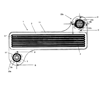
Figure 3a shows a top view of a joined bipolar plate 1 according to the
invention. The bipolar
plate consists of at least two layers 2 and 3, which are joined by laser
welding, as is indicated
9
CA 02711210 2010-07-26
by the welding seams 11, 11' and 11". The laser welding line 11 constitutes a
continuous
line. This means that the area encircling the channel structure - where
necessary
interrupted by supply and removal lines - is accordingly welded in a tight
manner. Further,
the areas of protrusions and indentations- which one is considered as which
depends from
the point of view, see reference numbers 2a and 2b - are joined to each other,
see the
dashed lines 11'. Further, the two layers of the bipolar plate 1 are also
connected to each
other in the area of the flow field by means of segmented straight welding
seams, the
position of which is indicated as an example by arrow 11".
The figure shows an upper first layer 2, below which the layer 3 can only be
identified in
sections, namely in the area of the bores. The diameter of the bores in the
area of the
indentations/protrusions is smaller in the lower layer 3, which provides a
small section to be
visible, as can be seen in the upper right part of figure 3a. This allows -
either by visual or
automated inspection - to verify whether the correct layers have been
assembled in a
correct manner.
The following focuses on the indentations/protrusions of the contact areas 23a
and 23b,
especially also by means of the sectional views B-B, see figure 3b, C-C and D-
D, see figures
3a, 3e and 3f. The corresponding cut-out schematic top-views to the areas D1
and D2 are
depicted in figures 3c and 3g. In addition, figure 3d explains the
relationship of the angles of
the indentations/protrusions of figure 3b. In this context, elements of the
lower layer being
in fact covered by the upper layer and therefore not visible, such as the
oblong
indentation/protrusion, are indicated by continuous lines. The same applies
also to figure 4a.
Figure 3a demonstrates that at the contact area 23a in both layers 2 and 3,
circular
indentations/protrusions 2a and 3a are provided. In contrast, contact area 23b
shows a
circular indentation/protrusion 2b in layer 2 and an oblong
indentation/protrusion 3b in
layer 3. These interlocking indentations/protrusions 2b and 3b show two
contact portions
30b and 31b. Compared to the circular protrusion 2b in layer 2, the
corresponding contact
portions 30b and 31b only extend in an extremely short section of the
circumference, they
are almost point-shaped, only. The contact portions 30b and 31b are situated
on opposing
sides of the circle and oppose each other. A virtual straight line through the
centre points of
the respective contact portions, 30b and 31b indicates a direction along which
no movement
is possible. This direction is essentially perpendicular both to the main
direction of the
channel structure 4 and the direction of the welding seams 11'. However, in
the direction
perpendicular to this virtual straight line, along line 5b, both layers can
move in a limited
range relative to each other which allows limited adjustment of tolerances or
relative
movements along the channel structures of both layers which are due to heat
induced
extension or due to the forming process.
Figure 3b shows a bipolar plate according to figure 3a, which is introduced
into the retainer
6c of a fixation device 6, e.g. the fixation device of a welding apparatus.
The fixation device
further shows a centring bolt 6a as well as radius 6b. The figure shows a
detailed view
according to section B-B, where below a first layer 2 - in the installed state
the anode-sided
layer - a second layer 3 is inserted, which second layer in the installed
state is the cathode-
sided layer. Both layers are made from thin metallic sheet, especially steel
sheet metal. A
first protrusion 2a of the first layer 2 is inserted into a first indentation
3a of the second layer
3. The mentioned indentation 3a and protrusion 2a are arranged in a way that
they come
CA 02711210 2010-07-26
into positive-fit in a plane El parallel to plane E, which means that no
translational
movement is possible in whatever direction of the plane. The plane E is
defined as the plane
of the plate which corresponds to the plane x-y according to figure 2.
These facts are further underlined by the orthogonal double arrows in the
simplified
representation of the area D1 without bores in figure 3c. There it is obvious
that in the plane
E and El, respectively, no movement is possible. The first protrusion and the
first
indentation 3a are thus arranged in a self-centring manner relative to each
other.
As is obvious from figure 3b, both the first protrusion 2a and the first
indentation 3a are
provided with a circular bore tax and 3ax, respectively. The diameter of this
bore 3ax of the
first indentation 3a is smaller than the diameter of the bore tax of the first
protrusion 2a.
The same ratio applies for the corresponding areas of the bores.
The fixation device itself in the area of the centring bolt shows the actual
receiving section
6c, which passes upwards with a rounded radius 6b towards plane E. The
receiving section
here shows the shape of a circular cylinder.
As can clearly be seen in figure 3d in a detailed view according to section F1
of figure 3b, the
angle of the cone a2 between the vertical and the outer shell surface of the
protrusion 2a is
slightly smaller than the angle a3 between this vertical and the inner shell
surface of the
indentation 3a. The vertical here corresponds to the direction of the main
axis of the
centring bolt 6a. This allows only for a linear, circumferential contact of
the outer shell
surface of the first protrusion 2a with the inner shell surface of the first
indentation 3a,
which leads to the positive fit in the plane El.
It is further obvious that the height h2 of the first protrusion 2a is smaller
than the
height/depth h3 of the indentation 3a. This causes that the first layer 2 does
not rest on the
second layer 3 in the area surrounding the centring bolt 6a and that the two
layers 2 and 3
only have contact to each other in the contact area corresponding to the
circumferential
contact line.
Figure 3e further shows a sectional view according to C-C in the area around a
second
centring bolt 6d of the fixation device 6. It is complemented by the section D-
D in figure 3f
which is orthogonal to the former. One can see a second protrusion 2b of layer
2, which is
circular and shows a circular, centred opening 2bx, which is arranged
concentric to the outer
shell of the second centring bolt 6d in the receiving section 6f. This second
protrusion 2b
engages with a second indentation 3b in the layer 3 arranged below the first
layer 2. As in
figure 3b, the cross section of the opening 3bx of the second indentation 3b -
at least in this
sectional view - is slightly smaller than the one of the corresponding opening
of the second
protrusion 2b. However, the second indentation 3b has an oblong shape, which
causes the
second protrusion in figure 3e to be movable in a limited range from left to
right which
means that there is no positive fit. In contrast to this, in section D-D of
figure 3f, a contact is
given between the protrusion 2b and the indentation 3b at the contact portions
30b, 31b in
the plane E2. This is emphasised in the simplified sketch of area D2 in figure
3g, in which a
representation of the bores has been desisted from. There, the vertical double
arrow
indicates that a movement of the second protrusion 2b within the second
indentation 3b in
11
CA 02711210 2010-07-26
y-direction is not possible. In contrast, the horizontal double arrow shows
the option for a
movement in x-direction for compensation purposes.
The following intends to indicate the typical scale of the invention. The
extension of the
indentation/protrusion in the x- or y-direction usually is between 2 and 25
mm, preferably
from 4 to 15 mm. The depth of the receiving section 6f around the centring
bolt corresponds
to about 0.5 to 1 mm, the diameter of the receiving section 6f in the fixation
device 6
preferably ranges between 2 to 30 mm. The clearance of the openings, thus for
example of
the opening 2bx or 3bx relative to the centring bolt is usually between 0.1
and 3 mm,
preferably between 0.1 and 1 mm.
Figures 3a to 3g thus show a bipolar plate 1, which comprises at least two
layers 2, 3 with at
least two layers 2, 3, each showing a first and a second
indentation/protrusion, where the
first indentation/protrusion 2a of the first layer 2 and the first
indentation/protrusion 3a of
the second layer 3 in a completely positioned state of the layers 2, 3
interlock with each
other and contact in the plane El with positive fit, whereas the second
indentation/protrusion 2b of the first layer 2 and the second
indentation/protrusion of the
second layer 3 in the completely positioned state of the layers 2, 3 interlock
with each other
but contact each other only in at least two sections 30b, 31b, with the
contact portions 30b,
31b being arranged in such a manner that they are situated on both sides of a
virtual straight
line 5b, which extends in the main direction of the indentation/protrusion 3b
in the second
layer 3, and where in the plane E2 no positive fit between the
indentations/protrusions 2b
and 3b is established.
An alternative embodiment of a bipolar plate according to the invention is
shown in figures
4a to 4c. The explanations made above apply here, too, except for the
differences
mentioned in the following.
Figure 4a shows a top view of a bipolar plate 1' with the layer 3' being
arranged as upper
layer. The course of section E-E is explained in figure 4c in a top view on a
plate which shows
only the positioning embossments. The sectional view E-E itself is given in
figure 4b. Figure
4b shows how the protrusions interlock with the indentations, namely
protrusion 2a' with
indentation 3a', protrusion 2b' with indentation 3b' and protrusion 2c' with
indentation 3c'.
There are thus three contact areas 23a', 23b' and 23c', each with a pair of
indentations/protrusions comparable to figures 3e to 3g. This means that the
indentations/protrusions of a contact area, e.g. of the contact area 23b' in
the plane E3
contact each other in two sections, respectively, with these contact portions
30b' and 31b'
being situated opposite to each other on both sides of the virtual straight
line 5b. The same
applies for the contact area 23a' in the plane E2 with the contact portions
30a' and 31a' and
the virtual straight line 5a as well as for the contact area 23c' in the plane
E4 with contact
portions 30c' and 31c' and the virtual straight line 5c. Planes E2, E3 and E4
are planes
extending parallel to plane E, they are however not indicated in the figures.
The virtual
straight line 5a at the contact area 23a' and the virtual straight line 5b at
the contact area
23b' in the example shown extend essentially in parallel and therefore allow a
limited
adjustment in this direction, namely in parallel to the main direction of the
channel structure
4 and therefore also in the direction of the welding seams 11". The virtual
straight line 5c
runs essentially orthogonal to the former two virtual straight lines 5a and 5b
and is arranged
12
CA 02711210 2010-07-26
essentially in the middle of the contact areas 23a' and 23b'. This virtual
straight line 5c
indicates the adjustment direction at the contact portion 23c'.
Figures 4a to 4c thus show a bipolar plate 1' which comprises at least two
layers 2', 3', with
the at least two layers 2', 3' each comprising a first, a second and a third
indentation/protrusion. The first indentation/protrusion of the first layer
interlocks with the
first indentation/protrusion of the second layer, the second
indentation/protrusion of the
first layer interlocks with the second indentation/protrusion of the second
layer and the
third indentation/protrusion of the first layer interlocks with the third
indentation/protrusion of the second layer. This leads to the layers
contacting each other in
the planes E2, E3 and E4 only in sections, namely in at least two sections
30a', 31a', 30b',
31b', 30c' and 31c' with these contact sections 30a', 31a, 30b', 31b', 30c'
and 31c' being
arranged in such a way that they are located on opposite sides of a virtual
straight line 5a, 5b
and 5c, respectively, which straight lines extend in the main direction of the
indentations/protrusions 3a', 3b' and 3c', respectively. No positive fit is
established between
the corresponding indentations/protrusions, 2a' and 3a', 2b' and 3b' as well
as 2c' and 3c' in
the planes E2, E3 and E4, respectively. The virtual straight lines 5a and 5b
extend under an
angle of -10 to 10 to each other, while the virtual straight line 5c runs at
an angle between
80 and 100 to the virtual straight lines 5a and 5b.
Possibilities for the design of the interlocking indentations/protrusions 2a,
3a, 2b, 3b, 2a',
3a', 2b', 3b', 2c' and 3c' of the first and second layer 2, 3, respectively,
are depicted in figure
based on eight different examples. The examples in figures 5a to 5d show
examples, which
lead to a positive fit between the indentations/protrusions in their
respective contact plane,
while the examples of figures 5e to 5h do not result in a positive fit between
interlocking
indentations/protrusions. A representation of possible bores for centring
bolts or for the
control of a correct assembly of the layers has been dispensed with for
clarity of the
drawings. Figure 5a shows how two circular indentations/protrusions interlock.
The circular
indentations/protrusions 2a, 3b contact each other circumferentially, as
already shown in
figures 3b and 3c.
Figure 5b shows a triangular indentation/protrusion 2a, which interlocks with
a circular
indentation/protrusion 3a and contacts the latter at the corners of the
triangle. These three
contact points are sufficient for providing a positive fit between the
indentations/protrusions 2a and 3a. A larger number of contacting corners of a
polygon also
results in a positive fit, as is shown on the example of figure 5c. There, a
rectangular
indentation/protrusion interlocks into a circular indentation/protrusion and
contacts the
latter in the contact plane at is four corners. In order to prevent
unnecessary abrasion of the
tools, polygons with rounded corners are preferred over such ones with sharp
corners.
Figure 5d indicates that interlocking of an oblong indentation/protrusion 2a
into a circular
indentation/protrusion may lead to a positive fit, too, provided that the
dimensions fit.
Inversely, a circular indentation/protrusion interlocking with an oblong
indentation/protrusion can only lead to a local contact of the interlocking
indentations/protrusions but not to a positive fit, as follows from figure 5e
and had already
been demonstrated in figures 3e to 3g.
13
CA 02711210 2010-07-26
Interlocking of an indentation/protrusion with the shape of an equilateral
polygon, e.g. a
square 2b, into an oblong indentation/protrusion 3b, will lead to contact
portions at the
corners as shown in figure 5f, or to contact portions at the lateral edges,
not shown here.
Thus, it depends on the relative orientation of the indentations/protrusions
which situation
applies. It is also possible that two oblong indentations/protrusions 2b, 3b
engage with each
other and - provided their respective width fits - contact each other along
their lateral
edges. In this situation it depends on the choice of the respective length of
the
indentations/protrusions whether a positive fit is established or not. As long
as the outer
extension of the engaging indentation/protrusion is smaller than the inner
extension of the
receiving indentation/protrusion, no positive fit results.
In addition, figure 5h shows that the contact of the interlocking
indentations/protrusions
does not have to be limited to two portions, being situated on opposite sides
of the virtual
straight line 5b, but that a different number of contact portions or contact
points, especially
even a different number on both sides of the virtual straight line 5b, is
possible when
realizing the engagement without positive fit.
Figure 6 shows an embodiment of the bipolar plate 1 according to the
invention, in which
the positioning embossment of both layers is formed in such a way that it
protrudes beyond
both sides of the plate plane E. In the upper layer for instance a protrusion
3a* with a height
h3x is formed, which - the figure shows the circular positioning embossment -
has a
diameter d3. Inside this circular protrusion 3a*, a circular indentation 3a+
is arranged, which
has a height h3i with the height h3i being larger than h3x, which means that
the indentation
3a+ is lowered relative to the plate plane E. The positioning embossment of
layer 2 is
designed in a comparable manner except for the diameter d2 of the protrusion
2a*, d2,
being smaller than the one of the protrusion 3a*, d3, so that the upper
protrusions 2a*, 3a*
only cause an optimization of the height ratios within the layer but do not
contribute to the
actual positioning or positive fit, respectively. Figure 6 further
demonstrates that the total
height of the positioning embossment in both layers, he, essentially
corresponds to the total
height of the channel structure 4, hf, so that the positioning embossment does
not impair
the sealing in the area of the outer edge of the bipolar plate, which edge is
however not
shown here.
In the embodiment shown in figure 7 the bipolar plate 1 shows in total three
layers 2, 100
and 3. The central layer 100 in the area of the contact areas 23a and 23b,
respectively,
shows recesses, the extension of which is sufficiently large in order to allow
the indentations
3a and 3b, respectively, to pass through into the indentations 2a and 2b,
respectively. The
positioning of both outer layers 2, 3 is effected in the manner described
beforehand for two-
layered embodiments but with the third layer being kept in between. Such a
solution is
possible no matter whether the indentations 2a, 2b, 3a, 3b are provided with
through holes
as depicted or not.
Figure 8 shows an example of welding a first layer 2 to a second layer 3 in
the area of the
channel structure 4 using a laser beam 12. Both layer 2 and layer 3 comprise
channel
structures with the sections to be welded to each other, e.g. the narrow
portion in the
middle of figure 8, lying flat one on the other. As an example of the scale,
the width of the
flat section of the first layer 2 is specified here to be 200 pm, while the
contact face of layer
3 has a width of 170 pm. The width of the laser beam 12 in this area is about
50 pm. The
14
CA 02711210 2010-07-26
invention provides for the contact areas to have an overlapping area with a
width of at least
100 m, which causes an joining connection - a welding connection - being
securely located
within the contact area between the first layer 2 and the second layer 3, even
with a slight
imprecision of the course of the laser beam.
To do so, the layers 2 and 3 are arranged one on top of the other as shown in
figures 3a to
3g using corresponding centring bolts 6a and 6d, respectively, using the
herein described
positioning embossments and the foregoing described receiving section of the
fixation
device 6 and the layers are welded to each other.
The description of the foregoing examples is only to be understood as
exemplary. It is
stressed that the combinations of all embodiments shown here is in the frame
of the
invention and that the subjects of the dependent claims, as far as not
explicitly excluded, can
be combined in any order.