Note : Les descriptions sont présentées dans la langue officielle dans laquelle elles ont été soumises.
CA 02716588 2010-10-05
1
Field of invention
The present invention concerns a ski pole. More specifically, the invention is
directed to an aerodynamically favorable ski pole.
Background of the invention
Hand held ski poles have been used together with skies for centuries,
primarily for
helping the skier maintain balance when skiing, but also to help the skier get
traction for movement in a forward direction. When modern skiing was in its
infancy almost 200 years ago, a single pole was often used. However, in modern
skiing two poles are used both for downhill and cross country skiing.
As modern skiing is constantly developing, focus is put on the development of
new
and improved skiing equipment to further advance the sport. Ski poles have
been
transformed fundamentally from the single pole of the 19th century to the
light
weight versions of today, when the skier carries one pole in each hand.
Traditionally, the typical cross country ski pole, and also the downhill
versions of
the poles, has been a circular hollow tube fitted with a handle, a disc or a
snow
guard for keeping the pole from sinking too far into the snow, and a spike in
the
bottom end to ensure traction. This is more or less still the general design
of a
modern ski pole of today. However, as the sport of skiing is constantly
developing,
there is a constant search and demand for improved solutions to provide new
ski
poles which are better suited to the sport of skiing.
Thus, the object of the present invention is to provide a ski pole which is
better
suited to modern skiing than the ski poles known from the field. This is
achieved by
the ski pole as claimed in the present application.
Relevant prior art is disclosed in SU 1782173 A3, NO 300032 B1, US
2003/0227167 Al, and US 5505492 Al.
Short description of the Figures
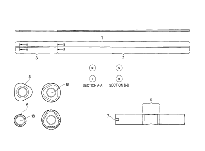
Figure 1 illustrates one embodiment of the ski pole according to the
invention,
wherein the ski pole 1 in one section 2 has a triangular cross section 4, and
wherein
in the other section 3, the cross section is circular 5; and wherein section 3
comprises a diameter distorted section 6 and a slot 7; and wherein the ski
pole is
hollow, or has a hollow core 8.
CA 02716588 2010-10-05
2
Detailed disclosure of the invention
In one embodiment, the present invention concerns a ski pole 1, in which the
cross
section of said pole in one end is triangular 2, and in which the cross
section of said
pole in the opposite end is circular 3; the cross section of said pole
gradually
adopting a triangular 4 or circular 5 cross section moving along the ski pole
from
one end to the opposite end. Preferably, the top end of the ski pole has a
triangular 4
cross section, and the bottom end of the ski pole has a circular 5 cross
section.
In another embodiment, the ski pole 1 according to the invention may be one
wherein the outer diameter of said pole is gradually decreasing from one end
towards the other end of the pole. The ski pole of the invention may also have
its
greatest outer diameter at a point between the two ends of said ski pole.
In yet another embodiment, the ski pole 1 according to the invention may have
its
greatest outer diameter in the triangular cross sectional end 2; and the outer
diameter of the ski pole may be gradually decreasing from the far end of this
triangular cross sectional end 2 of the ski pole towards the circular cross
sectional
end 3 of the ski pole of the invention.
In another embodiment, the ski pole 1 according to the invention may be
hollow.
The ski pole of the invention may also be produced with a hollow core 8. In a
more
specific embodiment, the cross section of the hollow core 8 may be circular
over the
total length of the ski pole 1 of the invention. However, the hollow core 8
may have
other geometrical cross sectional shapes over the length of the ski pole of
the
invention, such as rhomboid, triangular, rectangular, square, pentameric,
hexameric
etc., or a combination of any such geometrical shape.
In a further embodiment of the ski pole 1 according to the invention, at a
distance
from one end of the ski pole, the pole may comprise a section 6 with a
slightly
distorted diameter compared to the section immediately preceding and following
said diameter distorted section 6. Preferably, this diameter distorted section
6 may
be located at a distance from the bottom end of the ski pole, in the end of
the ski
pole having a circular cross section 3. This diameter distorted section 6 may
function as a friction increasing feature to enhance fixation of a replaceable
means
for limiting the sinking of the ski pole into ground surfaces, such as a disc
structure
or a snow guard, when the ski pole is used for skiing or walking.
In one embodiment, the diameter distorted section 6 may have a length along
the ski
pole of about 5-40 mm, more preferably about 10-30 mm, and most preferably
about
15-25 mm. The diameter distorted section 6 may be placed about 10-40 mm from
one end of the ski pole of the invention, more preferably about 20-30 mm from
one
CA 02716588 2010-10-05
3
end, and most preferably about 22-28 mm from one end of the ski pole of the
invention.
The diameter distorted section 6 of the above embodiments is primarily a
feature
which is designed to enhance friction when a stopper means is used to firmly
fix a
replaceable means for limiting the sinking of the ski pole into ground
surfaces, such
as a disc structure or a snow guard. The stopper, which is designed to be
compatible
with the replaceable means for limiting the sinking of the ski pole into
ground
surfaces, is aided in its stopper function by the enhanced friction of the
diameter
distorted section 6. Preferably, the diameter distorted section 6 may have a
cross
sectional diameter less than the cross sectional diameters of the sections
immediately preceding and following said diameter distorted section 6.
However,
the diameter distorted section 6 may have a cross sectional diameter which is
greater than the cross sectional diameters of the sections immediately
preceding and
following said diameter distorted section 6.
In a further embodiment of the ski pole of the invention 1, the ski pole may
further
be configured with features for securing attachment and correct positioning of
an
unsymmetrical replaceable means for limiting the sinking of the ski pole into
ground surfaces, such as a disc structure or a snow guard, in a desired
direction
relative to the shape of the ski pole. In a preferred embodiment of the
invention, this
feature for securing attachment in a desired direction of such unsymmetrical
means
may be a slot 7 placed diametrically across the circular cross sectional end 3
of the
ski pole. This slot 7 may also be place slightly off centre, or it may be
placed off
centre to such a degree that the slot is a recess. The slot 7 may preferably
be about
1-10 mm deep, more preferably 2-8 mm deep, and most preferably 3-6 mm deep.
However, it is contemplated that the slot 7 of this preferred embodiment may
be
replaced with other features for achieving the same result, such as one or
more lips
on the ski pole in the same area as the slot, or along the side of the ski
pole in this
area. It is also possible to achieve the same result with two or more slots.
In another embodiment of the ski pole 1 of the invention, the ski pole may
have
incorporated means for enhancing the grip of the pole onto ground surfaces.
This
may be achieved by fitting the ski pole with a spike structure in the end of
the ski
pole facing the ground when it is used for skiing or walking. The spike
structure
may be formed from any material which provides the material strength necessary
for providing a grip on the desired surface.
The ski pole of the present invention has the following advantages over the
prior
art. Firstly, by the substantially triangular shape of the ski pole of the
invention, the
ski pole avoids the problem of the pole being forced out of a strictly forward
directed motion, relative to the direction of the skier holding the ski pole.
CA 02716588 2010-10-05
4
Traditional tube formed or elliptic formed ski poles produce a drag and/or a
lift
when the skier push them forward into a pendulum movement; and this drag/lift
causes the ski pole to wander off to either left or right. This drag forced
deviation
from a strict pendulum movement has the effect that the skier must use
unnecessary
force to correct the trajectory of the ski pole into a strictly forward
directed motion.
For the athlete cross country skier, this is of course a major disadvantage
over a set
distance, because this unnecessary extra force does not contribute to the
skier's
forward motion. Moreover, for the downhill skier, a ski pole that behaves like
an
aero plane wing makes the ski pole unstable, which may cause the ski pole to
interfere with the skier by behaving unpredictably. The substantially
triangular
cross sectional shape of the ski pole of the invention also requires less
material to
be used for the production of the pole as compared to a ski pole with a
circular cross
section. The ski pole of the present invention will as a consequence have less
weight than a corresponding substantially circular cross sectional ski pole
made of
the same material.
As mentioned above, the ski pole of the present invention, by its
substantially
triangular shape, avoids this problem by reducing the drag forces when the ski
pole
is used for skiing. By placing a handle on top of the ski pole in the correct
orientation relative to the cross sectional shape of the ski pole, the ski
pole is
arranged with one of the three sides of the triangular shape of the pole
facing
directly forward into the direction of movement of the skier holding the ski
pole of
the invention. Surprisingly, this orientation of the triangular ski pole of
the
invention has proved significantly advantageous in reducing drag. A skier
using the
ski pole of the invention does not experience the need to use extra and
unnecessary
effort to force the ski pole into a strictly forward directed pendulum motion,
because the ski pole of the invention, by its novel features, does not require
a
correction of trajectory.
A second advantage of the ski pole of the invention is the gradually reduced
cross
sectional area towards the bottom end of the ski pole. When a ski pole is used
for
cross country skiing, the bottom end is moved forward by the skier in a
pendulum
movement. Thus, this end of the ski pole has the greatest angular speed when
used
for skiing. By the laws of physics; the more weight concentrated in this end
of the
ski pole, the more force is required by the skier to move it forward.
Consequently, it
is paramount to reduce the weight in this end of the ski pole as much as
possible to
minimize the force necessary to move the ski pole forward in a pendulum
movement. This is achieved by the shape of the ski pole of the invention,
which
gradually adopts a circular cross section towards the bottom end of the ski
pole.
This feature allows less material to be used in this end of the ski pole, and
consequently, the weight of the bottom end of the ski pole of the invention is
kept
low.
CA 02716588 2010-10-05
A third advantage of the ski pole of the invention is that it is designed to
allow glue
less or adhesive less fixation of replaceable means for limiting the sinking
of the ski
pole into ground surfaces, such as a disc structure or a snow guard.
Traditionally,
ski poles are fitted with a disc or snow guard to prevent the ski pole from
sinking
5 too far into the snow. One pair of ski poles is usually manufactured with
one type of
disc or ski guard, and these are glued or otherwise firmly fixed to the ski
pole. That
is, commercial ski poles are sold with a disc or a snow guard which cannot
easily be
replaced. The ski pole of the present invention is designed to be fitted with
different
replaceable means for limiting the sinking of the ski pole into ground
surfaces, such
as symmetrical or unsymmetrical discs or snow guards, without the need of
using a
glue or adhesive. In addition, the ski pole of the invention, by its novel
features,
makes it possible to correctly fix an unsymmetrical disc or snow guard to the
ski
pole such that the unsymmetrical disc or snow guard is orientated correctly
relative
to the intended direction of the motion of the ski pole when this is used by a
skier.
At first hand, it might not seem like a decisive advantage to have glue less
fixation
of a disc or snow guard system onto a ski pole. However, for athlete skiers, a
reduced weight of the equipment they are using in a competition situation is
welcome and necessary in order to gain an advantage over their competitors. In
this
way, the elimination of the need for a glue or adhesive in the ski pole of the
invention is fully in line with the object of the invention, which is to
provide a light
weight aerodynamically favorable ski pole. Moreover, to eliminate the need for
using a glue or adhesive in the bottom part of the ski pole of the invention,
which as
explained above is the part of the ski pole having the greatest angular speed,
has a
far greater influence on the force required to operate the ski pole by the
skier than
the few grams lost would initially seem to the untrained eye. This is because
the
skier operates and applies force to the ski pole from the top end in order to
move the
bottom end into a pendulum movement. Thus, the weight moved is not just the
mass
of the bottom end, but the mass of the bottom end in relation to the length of
the
pole. For the skier, this experienced weight is bigger, and, any reduction of
weight
in the bottom en of the ski pole reduces the force necessary to operate the
ski pole
far more than the lost weight would mean in pure weight.
In addition, the possibility to replace the means for limiting the sinking of
the ski
pole into ground surfaces, such as a disc or snow guard system, whenever this
is
desired by the skier, provides another advantage for the ski pole of the
invention.
This allows the skier to easily replace the disc or ski guard system in
accordance
with the consistency of the snow. The skier is then in a position to always
ensure
that a disc or snow guard system with as little weight as possible is used for
the ski
pole of the invention.
Consequently, the three major advantages of the ski pole of the invention,
i.e., the
aerodynamically favorable shape, the elimination of glue or adhesive to fix
the
replaceable means for limiting the sinking of the ski pole into ground
surfaces and
CA 02716588 2010-10-05
6
the possibility to replace the means for limiting the sinking of the ski pole
into
ground surfaces, all contribute to the object of the invention, which is to
provide a
favorable ski pole better suited to modern skiing than the ski poles known
from the
field. The ski pole of the invention may be used in cross country skiing,
downhill
skiing, rollerbiading or roller skiing and for walking.
20