Note : Les descriptions sont présentées dans la langue officielle dans laquelle elles ont été soumises.
CA 02888416 2015-04-16
WO 2014/067868 PCT/EP2013/072383
METHODS OF MANUFACTURING BLADES OF TURBOMACHINES BY WIRE
ELECTRIC DISCHARGE MACHINING, BLADES AND TURBOMACHINES
DESCRIPTION
TECHNICAL FIELD
Embodiments of the subject matter disclosed herein generally relate to blades
for
turbomachines, turbomachines using such blades and methods of manufacturing
such
blades; more specifically, they relate to stator blades for steam turbines,
steam turbines
using such blades and methods of manufacturing such blades.
BACKGROUND ART
In steam turbines, partial condensation of the steam occurs at their last
stage or stages.
In particular condensation occurs on the airfoil portion of the stator blades
of a so-called
"condensing stage", typically the last stage of the turbine.
If droplets are generated as a consequence of condensation, they leave the
static stator
blades and they hit the rotating rotor blades; therefore, damages to the rotor
blades may
occur.
In order to reduce the damages caused by the droplets, the rotation speed of
the rotor
blades may be reduced; but in this way, the efficiency of the turbine is also
reduced.
Alternatively, in order to reduce any damage on the rotor blades, solutions
exist for
collecting the condensation before the generation of droplets.
The most typical of these solutions consists in using hollow stator blades
where
condensation is likely to occur, providing holes and/or slots through the
airfoil portion of
the blades extending from the airfoil surface to the internal cavity, and
sucking from the
internal cavity so to that any condensation leaves the airfoil surface and
enters the internal
cavity. In this way, droplets on the airfoil surface of the stator blades are
not generated and
.. released ¨ to be precise, droplets generation can not be completely
avoided, but is simply
highly reduced.
1
260448
Manufacturing of a hollow stator blade for steam turbines has traditionally
been done by
starting from two metal sheets; thereafter, the two metal sheets were molded
in such a way
as to form two half-shells; then, the two half-shells were welded together;
finally, some
finishing was often done.
Sometimes, a different manufacturing method has more recently been used (see
e.g. figure
1):
- taking two metal bars,
- milling them separately so to define the surface of the internal cavity
(see e.g. figure 1A),
- welding them together so to obtain a hollow piece (see e.g. figure 1B),
- mill finishing the hollow piece so to define the airfoil surface (see e.g.
figure 1C).
This manufacturing method allows to define quite precisely the internal
surface of the
blade, i.e. the surface of the internal cavity, and quite precisely the
external surface of the
blade, i.e. the airfoil surface. Anyway, it is quite expensive as the milling
operation (for
the inside and the outside) is relatively slow.
In turbines, especially gas turbines, hollow blades are sometime used for
rotor blades in
order to reduce weight of the rotating clement. These hollow blades are
typically obtained
through casting, particularly "investment casting", in order to obtain a
rotating element
having an extremely precise shape and size; anyway, this manufacturing method
is very
expensive especially when used for small-lot production (for example 100-1000
pieces).
SUMMARY
Therefore, there is a general need for a solution of blades, in particular
steam turbine
hollow blades, allowing an easier and more economical manufacturing without
sacrificing
shape and/or size precision. In particular, there is a need for a
manufacturing method that
does not require molds and that does require limited or no milling and/or
finishing and that
is different from casting.
2
CA 2888416 2018-08-21
260448
Additionally, it would be desirable to obtain a hollow blade in a single piece
integrating
not only the airfoil portion but also a root portion and a shroud portion.
Anyway, if the airfoil portion, the root portion and the shroud portion should
be three
separated pieces, it would be desirable to join them easily.
Finally, it would be desirable to manufacture modules comprising a set of
steam turbine
hollow blades in an easy way.
It is to be considered that one of the ultimate goals is to manufacture a
whole steam turbine
having good performances in a relatively easy way and at a reasonable cost.
The present inventors started from the realization that for a steam turbine
hollow blade the
shaped on the surface of the internal cavity is not particularly critical;
this is quite different
from the internal cavity of other kinds of hollow blades. On the other side,
the shape of
the airfoil surface is very important.
In the light of these observations, they thought of (A) realizing the blade in
a single piece,
(B) using milling for the airfoil surface so that its shape would be extremely
precise, (C)
using Wire Electric Discharge Machining, i.e. Wire EDM, for the internal
cavity so that it
would be sufficiently simple and easy to be realized and its shape would be
sufficiently
precise, i.e. the internal surface of the blade would much sufficiently well
with the external
surface of the blade.
By using Wire EDM, the surface of the internal cavity is a "ruled surface".
In this way, no welding is necessary for manufacturing the blade, the
precision of the
machine surface or surfaces of the blade is extremely high, and the thickness
of the lateral
wall of the airfoil portion of the blade may be very low.
This manufacturing method is particularly suitable and convenient for small-
lot production
(for example 100-1000 pieces).
The present inventors realized afterwards that the Wire EDM was suitable for
forming not
only the internal surface of a hollow turbine blade but also for forming both
the internal
and the external surfaces of a blades, even for long (for example up to 1000
mm) blades,
3
CA 2888416 2020-01-08
CA 02888416 2015-04-16
WO 2014/067868 PCT/EP2013/072383
provided these surfaces are designed as "ruled surfaces" or very close to such
kind of
surfaces.
A first aspect of the present invention is a blade for a turbomachine.
According to embodiments thereof, a blade for a turbomachine comprises an
airfoil
portion, wherein said airfoil portion extends longitudinally for a length and
has a first end
and a second end, wherein said airfoil portion is defined laterally by an
airfoil surface, and
wherein said airfoil surface is a ruled surface.
According to alternative embodiments thereof, a blade for a turbomachine
comprises an
airfoil portion, wherein said airfoil portion extends longitudinally for a
length and has a
first end and a second end, wherein said airfoil portion is defined laterally
by an airfoil
surface, wherein said airfoil portion has an internal cavity extending
entirely along said
length, and wherein said internal cavity is defined laterally by a ruled
surface.
Said airfoil surface may be a ruled surface.
The blade may be arranged as a stator blade for a steam turbine comprising a
root portion,
a shroud portion and an airfoil portion, wherein said airfoil portion extends
longitudinally
for a length and has a first end and a second end, said first end being
adjacent to said root
portion and said second end being adjacent to said shroud portion, wherein
said airfoil
portion is defined laterally by an airfoil surface, wherein said airfoil
portion has an internal
cavity extending entirely along said length, and wherein said internal cavity
is defined
laterally by a ruled surface.
At any point of the airfoil portion the distance (measured transversally to
the blade)
between said airfoil surface and said ruled surface may be variable.
At any point of the airfoil portion, the distance (measured transversally to
the blade)
between said airfoil surface and said ruled surface may be greater than lmm
and smaller
than 5mm.
At said first end there is a first offset between said airfoil surface and
said ruled surface;
said first offset may be constant and may be in the range from lmm and 5mm.
4
CA 02888416 2015-04-16
WO 2014/067868 PCT/EP2013/072383
At said second end there is a second offset between said airfoil surface and
said ruled
surface; said second offset may be constant and may be in the range from lmm
and 5mm
Said root portion, said shroud portion and said airfoil portion may be in a
single piece, and
said ruled surface may extend also through said root portion and said shroud
portion.
Said root portion and said shroud portion may be joined to said airfoil
portion at said first
and second ends. In this case, said root portion has a first (through) hole
having a shape
corresponding to the shape of said ruled surface at said first end, and said
shroud portion
has a second (through) hole having a shape corresponding to the shape of said
ruled
surface at said second end.
Said root portion may comprise a first sleeve having an external surface
mating with said
ruled surface of said airfoil portion at said first end. In this case, said
first sleeve may have
a first through hole defined laterally by a ruled surface.
Said shroud portion may have a second sleeve having an external surface mating
with said
ruled surface of said airfoil portion at said second end. In this case, said
second sleeve
may have a second through hole defined laterally by a ruled surface.
The blade may comprise one single root portion, one single shroud portion and
a plurality
of airfoil portions, wherein each of said airfoil portions extends
longitudinally for a length
and has a first end and a second end, each of said first ends being adjacent
to said root
portion and each of said second ends being adjacent to said shroud portion,
wherein each
of said airfoil portions is defined laterally by an airfoil surface, wherein
each of said airfoil
portion has an internal cavity extending entirely along said length, and
wherein said
internal cavity is defined laterally by a ruled surface.
Said root portion may be or comprise a plate, said plate being substantially
flat or curved
and having a hole.
Said shroud portion may be or comprise a plate, said plate being substantially
flat or
curved and having a hole.
Said airfoil portion typically has holes or slots extending from said airfoil
surface to said
internal cavity.
5
CA 02888416 2015-04-16
WO 2014/067868 PCT/EP2013/072383
A second aspect of the present invention is a turbomachine.
According to embodiments thereof, a turbomachine comprises a plurality of
blades as set
out above.
The turbomachine may be arranged as a steam turbine and comprising a plurality
of stator
blades as set out above (in particular with an internal cavity defined
laterally by a ruled
surface and integrating a root portion, a shroud portion and an airfoil
portion).
The turbomachine may comprise a plurality of stages, wherein stator blades as
set out
above (in particular with an internal cavity defined laterally by a ruled
surface and
integrating a root portion, a shroud portion and an airfoil portion) are used
only for the last
stages.
The turbomachine may comprise a plurality of stages starting with a first
stage and ending
with a last stage, wherein (typically only) said last stage comprises a
plurality of stator
blades as set out above (in particular with an internal cavity defined
laterally by a ruled
surface and integrating a root portion, a shroud portion and an airfoil
portion).
The turbomachine may comprise an inner ring and a plurality of stator blades
as set out
above, wherein each of root portions of said stator blades are fixed (i.e.
welded or inserted
and welded or push fitted and welded) to said inner ring.
The turbomachine may comprise an outer ring and a plurality of stator blades
as set out
above, wherein each of shroud portions of said stator blades are fixed (i.e.
welded or
inserted and welded and push fitted and welded) to said outer ring.
The turbomachinc may be an axial-flow turbine.
A third aspect of the present invention is a method of manufacturing a blade
of a
turbomachine.
According to embodiments thereof, a method of manufacturing a blade of a
turbomachine
comprising an airfoil portion at least one external or internal surface of
said airfoil portion
is obtained by wire electric discharge machining.
6
CA 02888416 2015-04-16
WO 2014/067868 PCT/EP2013/072383
Said airfoil portion may extend longitudinally for a length and have a first
end and a
second end, wherein said airfoil portion may be defined laterally by an
airfoil surface, and
wherein said airfoil surface may be obtained by wire electric discharge
machining.
Said airfoil portion may extend longitudinally for a length and have a first
end and a
second end, wherein said airfoil portion is defined laterally by an airfoil
surface, wherein
said airfoil portion may have an internal cavity extending entirely along said
length,
wherein said internal cavity may be defined laterally by an internal surface,
and wherein
said internal surface may be obtained by wire electric discharge machining.
The manufacturing method may comprise the steps of:
A) providing a bar made of metal,
B) milling said bar externally, and
C) wire electric discharge machining said bar internally so that a through
hole is obtained
defined by a ruled surface.
Said through hole may have a length greater than 50 mm and smaller than 1000
mm.
The manufacturing method may comprise the further step of forging said bar
prior to
milling it.
Through step B external surfaces of said root portion, said shroud portion and
said airfoil
portion may be obtained.
Through step B only an external surface of said airfoil portion may be
obtained.
At said first end there is a first offset between said airfoil surface and
said ruled surface,
and wherein step C may be carried out so that said first offset being
constant.
At said second end there is a second offset between said airfoil surface and
said ruled
surface, and wherein step C may be carried out so that said second offset
being constant.
Said root portion may be (laser) welded to said airfoil portion at said first
end.
Said shroud portion may be (laser) welded to said airfoil portion at said
second end.
7
CA 02888416 2015-04-16
WO 2014/067868 PCT/EP2013/072383
A plurality of airfoil portions may be (laser) welded to the same root
portion.
A plurality of airfoil portions may be (laser) welded to the same shroud
portion.
Said root portion and said airfoil portion may be brazed together at said
first end.
Said shroud portion and said airfoil portion may be brazed together at said
second end.
Said root portion may have a first through hole, and said first through hole
may be
obtained by wire electric discharge machining.
Said shroud portion may have a second through hole, and said second through
hole may be
obtained by wire electric discharge machining.
Said root portion may be (laser) welded to an inner ring of a steam turbine.
Said shroud portion may be (laser) welded to an outer ring of a steam turbine.
Through step B at least an external surface of said airfoil portion may be
obtained; in this
case, the further step of making (transversal) holes or slots extending from
said external
surface to said (longitudinal) through hole is carried out after step C. Said
holes or slots
are advantageously obtained by electric discharge machining.
Through step B at least an external surface of said airfoil portion may be
obtained; in this
case, the further step of making (transversal) holes or slots extending from
said external
surface to said (longitudinal) through hole is carried out before step C. Said
holes or slots
are advantageously obtained by laser drilling or cutting.
BRIEF DESCRIPTION OF DRAWINGS
The accompanying drawings, which are incorporated herein and constitute a part
of the
specification, illustrate embodiments of the present invention and, together
with the
description, explain these embodiments. In the drawings:
Fig. 1 shows very schematically a manufacturing method of a steam turbine
hollow
blade that can be implemented according to the prior art or according to the
present
invention,
8
CA 02888416 2015-04-16
WO 2014/067868 PCT/EP2013/072383
Fig. 2 shows very schematically a first manufacturing method of a steam
turbine hollow
blade according to the present invention,
Fig. 3 shows very schematically a second manufacturing method of a steam
turbine
hollow blade according to the present invention,
Fig. 4 shows very schematically a first possibility of assembling a steam
turbine hollow
blade according to the present invention following the method shown in Fig. 2,
Fig. 5 shows very schematically a second possibility of assembling a steam
turbine
hollow blade according to the present invention following the method shown in
Fig. 2,
Fig. 6 shows very schematically a first possibility of assembling a steam
turbine hollow
blade module according to the present invention,
Fig. 7 shows very schematically and partially a first steam turbine stage
according to the
present invention,
Fig. 8 shows very schematically a second possibility of assembling a steam
turbine
hollow blade module according to the present invention,
Fig. 9 shows very schematically and partially a second steam turbine stage
according to
the present invention,
DETAILED DESCRIPTION
The following description of the exemplary embodiments refers to the
accompanying
drawings. The same reference numbers in different drawings identify the same
or similar
elements. The following detailed description does not limit the invention.
Instead, the
scope of the invention is defined by the appended claims.
It is to be noted that in the accompanying drawings sometimes sizes have been
exaggerated
for the sake of clarity; in other words they are not perfectly in scale
between each other.
Reference throughout the specification to "one embodiment" or "an embodiment"
means
that a particular feature, structure, or characteristic described in
connection with an
embodiment is included in at least one embodiment of the subject matter
disclosed. Thus,
9
CA 02888416 2015-04-16
WO 2014/067868 PCT/EP2013/072383
the appearance of the phrases "in one embodiment" or "in an embodiment" in
various
places throughout the specification is not necessarily referring to the same
embodiment.
Further, the particular features, structures or characteristics may be
combined in any
suitable manner in one or more embodiments.
The blades of a turbomachine (a compressor, an expander, a turbine, ...)
consist of or
comprise an airfoil portion. The airfoil portion extends longitudinally for a
certain length
between a first end and a second end; in general, its cross-section varies
along its length.
The airfoil portion has basically one surface to be formed that is the
"external lateral
surface" or "airfoil surface" of the blade that is very important for the
operation of the
airfoil portion. For certain applications, the airfoil portion is hollow, i.e.
it has an internal
cavity that, depending on the specific application and the specific design,
extends entirely
or partially along its length; for example, in the blade of figure 1, the
internal cavity
extends along the entire length of the blade. The internal cavity is defined
laterally by a
surface that may be called the "internal lateral surface" or, simply, the
"internal surface" of
the blade; in general, the cross-section of the internal cavity varies along
its length;
anyway, depending on the specific application and the specific design, the
variation in the
cross-section of the internal cavity may be different from the variation in
the cross-section
of the airfoil portion; in other words the thickness of the lateral wall of
the airfoil portion
may vary along its length and even from point to point.
According to the present invention, at least one external or internal surface
of the airfoil
portion is obtained by wire electric discharge machining, i.e. "Wire EDM".
This
particularly applies to the blades of turbomachines for "Oil & Gas"
applications; for the
last stage of a steam turbine, stator blades have a length in the range from
50 mm up to
1000 mm.
A first possibility is to form by Wire EDM only the external surface, i.e. the
airfoil surface;
for example, Wire EDM may be used, in figure 1, for machining the piece of
figure 1B and
obtaining the piece of figure 1C, and, in figure 2, for machining the piece of
figure 2A and
obtaining the piece of figure 2B.
A second possibility is to form by Wire EDM only the internal surface, i.e.
the surface of
the internal cavity; for example, Wire EDM may be used, in figure 1, for
machining two
CA 02888416 2015-04-16
WO 2014/067868 PCT/EP2013/072383
separate bars and obtaining the two pieces of figure 1A, and, in figure 2, for
machining the
piece of figure 2B and obtaining the piece of figure 2C.
A third possibility is to form by Wire EDM both the external surface and the
internal
surface of the airfoil portion.
By Wire EDM only a "ruled surface" may be obtained; it is to be noticed that,
by this term,
it is meant not only a "simple" ruled surface, but also a "complex" ruled
surface deriving
from a combination of two or more ruled surfaces, for example a large conical
surface at
the bottom and a small cylindrical surface at the top.
Although many differences surfaces may be obtained by Wire EDM, if this
technology is
to be used, the design of the blade should take it into account; for example,
the aim should
be to find ideal shapes of the surfaces of the blade that are exactly ruled
surfaces or are
sufficiently close to ruled surfaces. When this is not possible, milling can
be used instead
of Wire EDM; it is to be noticed that, depending on the specific application,
the need for
milling, instead of Wire EDM, may apply to any of the blade surface. For sure,
Wire EDM
may very advantageously be used when shape and size precisions are not
extremely high
such as for the surface of the internal cavity of a stator blade of a steam
turbine.
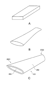
With reference to figure 2, a manufacturing method of a blade 201, consisting
only in an
airfoil portion 202, comprises the steps of:
A) providing a bar made of metal (figure 2A),
B) milling the bar externally (figure 2B), and
C) wire electric discharge machining the bar internally so that a through hole
205 is
obtained defined by a ruled surface (figure 2C).
With reference to figure 3, a manufacturing method of a blade 301 comprises
the steps of:
providing a bar made of metal, forging the bar (figure 3A), milling the bar
externally
(figure 3B), and wire electric discharge machining the bar internally so that
a through hole
305 is obtained defined by a ruled surface (figure 3C).
11
CA 02888416 2015-04-16
WO 2014/067868 PCT/EP2013/072383
According to the embodiment of figure 3, by first forging and then milling,
not only the
external surface of the airfoil portion 302 is obtained, but also the external
surfaces of a
root portion 303 and a shroud portion 304 both adjacent to the airfoil portion
302; the
through hole 305 extends not only along the entire length of the airfoil
portion 302, but
also inside the root portion 303 and the shroud portion 304; in this case the
root portion
and the shroud portion are integral with the airfoil portion.
According to those embodiments of the present invention wherein the airfoil
portion is not
integral with case the root portion and the shroud portion, one step of the
manufacturing
method is used for forming only the external surface of the airfoil portion
(see e.g. figure
2B).
In this case, at a first end (2021 in figure 2C) of the airfoil portion there
is a first offset
between the airfoil surface and the ruled surface, and Wire EDM may be carried
out so that
this first offset be constant.
In this case, at a second end (2022 in figure 2C) of the airfoil portion there
is a second
offset between the airfoil surface and the ruled surface, and Wire EDM may be
carried out
so that this second offset be constant.
Typically these two features are implemented together.
The embodiment of figure 4, is a blade 401 comprising an airfoil portion 402,
a root
portion 403 and a shroud portion 404; the airfoil portion 402 may be
manufactured
similarly to the airfoil portion 202 in figure 2.
The root portion 403 is welded, advantageously laser welded, to the airfoil
portion 402 at a
first end 4021 thereof.
The shroud portion 404 is welded, advantageously laser welded, to the airfoil
portion 402
at a second end 4022 thereof.
A similar manufacturing approach is used for the blade 601 in figure 6. In
this case, the
blade comprises a plurality of airfoil portions 602 (see figure 6A), in
particular three
(suitable numbers are in the range between two and five); the airfoil portions
602 are
welded, advantageously laser welded, to a same single shroud portion 604 (see
figure 6B);
12
260448
the same is true for a single root portion 603; in this way, multi-blade, or
"blade module",
601 is obtained (see figure 6C). It is to be noticed that the root portion 603
and the shroud
portion 604 are in the form of curved plates.
An alternative way to join the airfoil portion together with root portion
and/or the shroud
portion is by means of brazing.
According to the embodiment of figure 5, a blade 501 is obtained by providing
an airfoil
portion 502, that may be similar to the airfoil portion 202 of figure 2, and
brazing it, at a
first end 5021, to a root portion 503 and, at a second end 5022, to a shroud
portion 504.
According to the particular embodiment of figure 5, the root portion 503
comprises a
(substantially flat) plate 5031 and a sleeve 5032; the sleeve 5032 is inserted
into the
internal cavity 505 of the airfoil portion 502. The sleeve 5032 has preferably
an external
surface mating with the ruled surface of the internal cavity 505 of the
airfoil portion 502 at
the first end 5021; in this way, a good brazing may be achieved. A very good
mating may
be achieved if Wire EDM is used for forming the internal surface of the
internal cavity 505
and milling is used for forming the external surface of the sleeve 5032; in
fact, Wire EDM
machines and milling machines are "computer aided" and therefore it is
possible to set the
same shape (or two very similar shapes) for distinct surfaces of two pieces.
Also sleeve
5032 is typically hollow, as shown in figure 5, and obtained by Wire EDM.
According to the embodiment of figure 5, a blade 501 is obtained by providing
an airfoil
portion 502, that may be similar to the airfoil portion 202 of figure 2, and
brazing it, at a
first end 5021, to a root portion 503 and, at a second end 5022, to a shroud
portion 504.
According to the particular embodiment of figure 5, the shroud portion 504
comprises a
(substantially flat) plate 5041 and a sleeve 5042; the sleeve 5042 is inserted
into the
internal cavity 505 of the airfoil portion 502. The sleeve 5042 has preferably
an external
surface mating with the ruled surface of the internal cavity 505 of the
airfoil portion 502 at
the first end 5021; in this way, a good brazing may be achieved. A very good
mating may
be achieved if Wire EDM is used for forming the internal surface of the
internal cavity 505
and milling is used for forming the external surface of the sleeve 5042; in
fact, Wire EDM
machines and milling machines are "computer aided" and therefore it is
possible to set the
13
CA 2888416 2018-08-21
CA 02888416 2015-04-16
WO 2014/067868 PCT/EP2013/072383
same shape (or two very similar shapes) for distinct surfaces of two pieces.
Also sleeve
5042 is typically hollow, as shown in figure 5, and obtained by Wire EDM.
Brazing may be used instead of welding also for multi-blades, or "blade
modules", as the
one in figure 6.
As an alternative to brazing for example in the embodiment of figure 5, an
appropriate glue
may be used; the glue must be selected taking into account the operating
conditions (for
example, temperature, pressure, flowing materials, ...) of the blade.
One or each of the root portion and the shroud portion may have a through
hole; this is the
case of the embodiments of e.g. figures 4, 5, 6.
In this cases, for example, these through holes may be obtained by Wire EDM;
in this way
a perfect match may be achieved between the shape of the internal cavity of
the airfoil
portion at an end and the shape of the hole of the root or shroud portion, and
a perfect
welding may be carried out; in fact, Wire EDM machines are "computer aided"
and
therefore it is possible to set the same shape (or two very similar shapes)
for distinct
elements.
Figure 7 shows an application of the blade 401 of figure 4; alternatively, the
blade 501 of
figure 5 or the multi-blade, or "blade module", 601 of figure 6 may be used
instead of the
blade 401 of figure 4. According to this embodiment, each of the root portions
403 of the
blades 401 are welded, advantageously laser welded, to an inner ring 708 of a
turbine, and
each of the shroud portions 404 of the blades 401 are welded, advantageously
laser welded,
to an outer ring 709 of a turbine; coupling between the root or shroud portion
and the
corresponding ring may be provided through a push fit or simply by a seat
positioning.
Specifically, figure 7 shows partially the array of the stator blades of the
last stage of a
(axial flow) steam turbine. This arrangement is very advantageously from the
construction
point of view.
Figure 8 shows a multi-blade, or "blade module", 807 corresponding to the a
plurality of
blades 301 of figure 3 adjacent to each other; the blades 301 may be welded
together or
not.
14
CA 02888416 2015-04-16
WO 2014/067868 PCT/EP2013/072383
Figure 9 shows an application of the multi-blade, or "blade module", 807 of
figure 8.
According to this embodiment, each of the root portions 303 of the blades 301
are welded,
advantageously laser welded, to an inner ring 908 of a turbine, and each of
the shroud
portions 304 of the blades 301 are welded, advantageously laser welded, to an
outer ring
909 of a turbine; coupling between the root or shroud portion and the
corresponding ring
may be provided e.g. through a complementary shaping and a guided insertion
(see figure
9).
Specifically, figure 9 shows partially the array of the stator blades of the
last stage of a
(axial flow) steam turbine. This arrangement is very advantageously from the
construction
point of view.
In case that the present invention is used for stator blades of a steam
turbine, holes and/or
slots are typically provided for sucking condensation.
According to a first possibility, holes or slots transversal to the blade and
extending from
the external surface of the airfoil portion to the internal surface of the
airfoil portion are
made after forming the internal cavity of the blade. In this case, the holes
or slots are
obtained by electric discharge machining.
According to a second possibility, holes or slots transversal to the blade and
extending
from the external surface of the airfoil portion to the internal surface of
the airfoil portion
are made preferably forming the internal cavity of the blade. In this case,
the holes or slots
are obtained by laser drilling or cutting.
The inner rings 708 and 908 and the outer rings 709 and 909 of figures 7 and 9
have
internal cavities extending all around the rings and in communication with
internal cavities
of the blades; such solution may be used for collecting condensation or for
other purposes
(for example circulating a fluid).
By using the manufacturing methods according to the present invention, novel
and
inventive turbomachine blades are obtained.
Essentially, at least one external or internal surface of the airfoil portion
of the blade is a
"ruled surface"; it is to be noticed that, by this term, it is meant not only
a "simple" ruled
CA 02888416 2015-04-16
WO 2014/067868 PCT/EP2013/072383
surface, but also a "complex" ruled surface deriving from a combination of two
or more
ruled surfaces.
In typical applications of the present invention, the internal cavity
extending entirely along
the entire length of the airfoil portion is defined laterally by a ruled
surface (see e.g. figure
2).
The blade may be designed so that, at any point of the airfoil portion, the
distance
(measured transversally to the blade) between the external surface and the
external surface
is variable; in particular, this distance is preferably greater than 1 mm and
smaller than 5
mm.
At a first end of the airfoil portion there is a first offset between the
external surface and
the internal surface; this first offset is advantageously constant and
preferably in the range
between 1 mm and 5 mm.
At a second end of the airfoil portion there is a second offset between the
external surface
and the internal surface; this second offset is advantageously constant and
preferably in the
range between 1 mm and 5 mm.
According to advantageous embodiments, the root portion, the shroud portion
and the
airfoil portion of the blade are in a single piece; in this case, the ruled
surface of the
internal cavity extends also through the root portion and the shroud portion
(see e.g. figure
3).
Alternatively, the root portion and the shroud portion are joined to the
airfoil portion at
their ends (see figures 4 and 5).
In this case, the root portion may have a first (through) hole having a shape
corresponding
to the shape of the ruled surface of the internal cavity at said first end,
and the shroud
portion may have second (through) hole having a shape corresponding to the
shape of the
ruled surface of the internal cavity at said second end (see figure 4).
Still in this case, but according to a different manufacturing method, the
root portion
comprises a first sleeve having an external surface mating with the ruled
surface of the
internal cavity of the airfoil portion at the first end, and the shroud
portion has a second
16
CA 02888416 2015-04-16
WO 2014/067868 PCT/EP2013/072383
sleeve having an external surface mating with the ruled surface of the
internal cavity of the
airfoil portion at the second end. In this case, the first sleeve has
typically a first through
hole defined laterally by a ruled surface and the second sleeve has typically
a second
through hole defined laterally by a ruled surface.
The construction details just described may be implemented not only in "single-
blades"
(for example 201 in figure 2, 301 in figure 3, 401 in figure 4 and 501 in
figure), but also in
"multi-blades", or "blade modules", (for example 601 in figure 6 and 807 and
figure 8).
The just described blades, whether "single-blades" or "multi-blades" may be
effectively
and efficiently used in the stages of turbomachines (see for example figure 7
and figure 9),
in particular in a stator blade array of the last stages, in particular the
very last stage, of a
steam turbine.
17