Note : Les descriptions sont présentées dans la langue officielle dans laquelle elles ont été soumises.
CA 02891617 2015-05-14
WO 2014/081540 PCT/US2013/067278
MODULAR PARALLEL BEAMFORMING SYSTEM
AND ASSOCIATED METHODS
TECHNICAL FIELD
[0001] Embodiments of this disclosure relate generally to signal
processing of sensor
arrays and more specifically to a modular parallel beamforming system and
associated methods.
BACKGROUND
[0002] Beamforming is a signal processing technique used to create
directional or spatial
selectivity of signals sent to or received from an array of sensors or an
array of antennas. These
arrays can be found in a variety of devices that transmit and receive
electromagnetic or acoustic
waves. Accordingly, this technique has numerous applications in radars,
sonars, seismology,
wireless communications, radio astronomy, acoustics, medical, and industrial
ultrasound
technologies.
[0003] In conventional beamforming, a source may transmit a wave that
propagates and
arrives at sensors of an array at different times, depending on the source
orientation and the array
geometry. To synchronize the arrival times throughout the array, outputs of
the sensors of the
array can be delayed and then aggregated to provide a beamforming output. In
some cases, the
outputs of the sensors of the array can be applied in different weights (to
decrease echo, for
example). The beamforming process can also be used to detect and estimate the
signal-of-
interest at the output of an array of sensors or antennas by means of optimal
spatial filtering and
interference rejection.
[0004] The array of sensors can include, for example, an array of
microphones or an
array of ultrasound piezoelectric crystals for receiving acoustic sound waves
or an array of
antennas for receiving electromagnetic waves. A beamforming technique can be
used to map
sound waves (e.g., in case of a sonar system), evaluate sound waves, or to
augment sound waves
using modifying and/or compensating delays and/or applying various weights.
[0005] FIG. 1 shows a block diagram of an example conventional beamformer
100,
which is also known in the prior art as a "delay-and-sum beamformer." As can
be seen from
FIG. 1, the beamformer 100 includes an array of sensors 105A ¨ 105Z, which may
include
microphones, antennas or other signal generating devices. The sensors 105A ¨
105Z are
operatively coupled to analog-to-digital (A/D) converters 110A ¨ 110Z,
accordingly. The A/D
1
CA 02891617 2015-05-14
WO 2014/081540 PCT/US2013/067278
converters 110A ¨ 110Z receive analog signals generated by the sensors 105A ¨
105Z and
generate corresponding digital signals for further processing. The digital
signals from each A/D
converter 110A ¨ 110Z are fed into a plurality of delaying units 115A ¨ 115Z.
Further, the
delaying units 115A ¨ 115Z delay digital signals received from the A/D
converters 110A ¨ 110Z
at slightly different times so that every signal may reach output at
substantially the same time. In
narrow-band systems, the time delay may be equivalent to "phase shifting" so
that the resulting
output signal, when all shifted signals are combined, is referred to as a
"phased array signal."
[0006] Further, in the beamformer 100, the signals from every delaying
unit 115A ¨
115Z may be amplified by applying different "weights." Different weighting
patterns (e.g.,
Dolph-Chebyshev) can be used to achieve the desired sensitivity patterns,
improve signal-to-
noise ratio, reduce blasting, or improve filtering. The weights can be applied
by a plurality of
multipliers 120A ¨ 120Z. Thus, both the delaying units 115A ¨ 115Z and the
multipliers 120A ¨
120Z can perform conditioning of the signals derived from the sensors 105A ¨
105Z depending
on a particular application.
[0007] With continuing reference to FIG. 1, the conditioned signals
outputted from the
multipliers 120A ¨ 120Z may be supplied to a summer 125. The summer 125
combines all
signals into a single phased array output signal, which can be then analyzed,
processed, played,
or in any other way utilized by another system or apparatus. The beamformer
100 may include
hardware components, software components, or a combination thereof
[0008] In various applications, the number of input signals, i.e.,
signals generated by the
sensors 105A ¨ 105Z, may differ. For example, in simple sonar systems, 16
sensors and,
correspondingly, 16 input signals can be used; however, in more complex
ultrasound testing
systems, there can be hundreds of input signals. In such complex cases,
beamformers may use a
large number of A/D converters, delaying units, and multipliers in order to
process such a big
number of input signals. However, due to conventional limitations of hardware
components, the
number of input signals that can be combined by a conventional summer is
typically less than
one or several tens. To address this problem, beamformers may be equipped with
more than just
one summer.
[0009] FIG. 2 shows a block diagram of an example conventional
beamforming system
200, which includes a plurality of beamformers 205A ¨ 205Z. As shown in the
figure, the
beamformers 205A ¨ 205Z are coupled in series such that a first output signal
of a first
beamformer 205A is supplied to a second beamformer 205B, in which the first
output signal is
2
CA 02891617 2015-05-14
WO 2014/081540 PCT/US2013/067278
combined with a second output signal, and so forth until the last beamformer
205Z generates a
phased array output signal.
[0010] FIG. 3 shows a block diagram of another example conventional
beamforming
system 300, which includes a plurality of beamformers. In this example of
conventional system
300, each beamformer 310A, 310B, and so forth include more than one summer. As
shown in
FIG. 3, the delaying units 115A ¨ 115Z may generate a plurality of signals
delayed by various
time periods and then separately supplied to multipliers and subsequently to
summers 305A ¨
305N so that each summer 305A ¨ 305N combines signals to which the same
weights were
applied. The beamformers 310A, 310B, and so forth are interconnected such that
the summers
305A ¨ 305N of each beamformer 310A, 310B and so forth are interconnected in
series as
shown in FIG. 3. Thus, the combined signals of the first summers 305A
pertaining to the
beamformers 310A, 310B, and so forth are summed together and outputted to a
post-processing
unit 315. Similarly, the summed signals of the second summers 305B and summed
signals of the
remaining multipliers are outputted into the same post-processing unit 315 as
shown in FIG. 3.
The post-processing unit 315 may process all such signals to generate a
desired phased array
output signal for further analysis.
[0011] Shortcomings of the conventional beamforming systems shown in FIG.
2 and
FIG. 3 may include the inability to adapt to various purposes because these
beamforming
systems may be only configured to process a predetermined number of signals
generated by the
sensors 105A-10Z. Thus, the conventional beamforming systems may require
significant
reconfiguration for varying purposes and numbers of sensors.
BRIEF DESCRIPTION OF THE DISCLOSURE
[0012] Some or all of the above needs and/or problems may be addressed by
certain
embodiments of the disclosure. According to one example embodiment, a modular
beamformer
and associated methods can be provided. The modular beamformer may comprise a
plurality of
signal generation units configured to generate digital signals. The signal
generation units may
include an ultrasound sensor and/or an A/D converter. The modular beamformer
may further
comprise a plurality of delaying units. The delaying units may be configured
to receive the
digital signals and adaptively delay the digital signals. The modular
beamformer may further
comprise a plurality of multipliers associated with the plurality of delaying
units. The
multipliers may be configured to generate conditioned digital signals by
processing the digital
signals delayed by the plurality of delaying units. The processing may include
dynamically
3
CA 02891617 2015-05-14
WO 2014/081540 PCT/US2013/067278
applying weights to the digital signals delayed by the plurality of delaying
units. The modular
beamformer may further comprise a plurality of summers configured to combine
the conditioned
digital signals to generate a phased array output signal.
[0013] According to another example embodiment, a beamforming system is
provided.
The beamforming system may comprise a plurality of modular beamformers. The
modular
beamformers may operatively be coupled to each other (for example, in parallel
to each other).
Each modular beamformer of the plurality of modular beamformers may comprise a
plurality of
signal generation units configured to generate digital signals. Each modular
beamformer of the
plurality of modular beamformers may further comprise a plurality of delaying
units configured
to receive the digital signals and adaptively delay output of the digital
signals. Each modular
beamformer of the plurality of modular beamformers may further comprise a
plurality of
multipliers assigned to the delaying units. Each multiplier may be configured
to generate
conditioned digital signals by adaptively applying weights to the digital
signals output by the
plurality of delaying units. Each modular beamformer of the plurality of
modular beamformers
may further comprise a plurality of summers configured to combine the
conditioned digital
signals to generate a phased array output signal.
[0014] According to yet another example embodiment, a method for signal
beamforming
is provided. The method may comprise generating digital signals by a plurality
of signal
generation units. The method may further comprise adaptively delaying, by a
plurality of
delaying units, output of the digital signals. The method may further comprise
generating, by a
plurality of multipliers assigned to each delaying unit, conditioned digital
signals by adaptively
applying one or more weights to the digital signals output by the plurality of
delaying units. The
method may further comprise combining, by a plurality of summers, the
conditioned digital
signals output by the plurality of multipliers to generate a phased array
output signal. Each
summer may combine adaptively delayed conditioned digital signals through the
plurality of
delaying units.
[0015] Additional systems, methods, apparatus, features, and aspects are
realized through
the techniques of various embodiments of the disclosure. Other embodiments and
aspects of the
disclosure are described in detail herein and are considered a part of the
claimed disclosure.
Other embodiments and aspects can be understood with reference to the
description and the
drawings.
4
CA 02891617 2015-05-14
WO 2014/081540 PCT/US2013/067278
BRIEF DESCRIPTION OF THE DRAWINGS
[0016] Having thus described the disclosure in general terms, reference
will now be
made to the accompanying drawings, which are not necessarily drawn to scale,
and wherein:
[0017] FIG. 1 shows a block diagram of an example conventional
beamformer.
[0018] FIG. 2 shows a block diagram of an example conventional
beamforming system
including a plurality of beamformers.
[0019] FIG. 3 shows a block diagram of another example of a conventional
beamforming
system including a plurality of beamformers.
[0020] FIG. 4 shows a block diagram of a beamforming system, according to
an example
embodiment.
[0021] FIG. 5 shows another a block diagram of a beamforming system,
according to an
example embodiment.
[0022] FIG. 6 shows a block diagram of a beamforming system, according to
an example
embodiment.
[0023] FIG. 7 shows a flow diagram illustrating a method for signal
beamforming,
according to an example embodiment.
DETAILED DESCRIPTION
[0024] Illustrative embodiments of the disclosure now will be described
more fully
hereinafter with reference to the accompanying drawings, in which some but not
all
embodiments of the disclosure are shown. Indeed, the disclosure may be
embodied in many
different forms and should not be construed as limited to the embodiments set
forth herein;
rather, these embodiments are provided so that this disclosure will satisfy
applicable legal
requirements. Like numbers refer to like elements throughout.
[0025] According to one or more embodiments of the present disclosure, a
beamforming
system may be provided for processing signals of an array of sensors or
antennas. The
beamforming system may include one or more modular beamformers, each of which
may
include a predetermined number of channels to process a corresponding
predetermined number
of sensor/antenna signals. The modular beamformers may be easily "stacked" or
interconnected
CA 02891617 2015-05-14
WO 2014/081540 PCT/US2013/067278
without the need for reconfiguration or altering of any software or hardware
components.
Accordingly, engineers and researchers may configure a desired beamforming
system by
combining a particular number of the modular beamformers based on particular
needs. As the
needs change, the beamforming system may be easily re-configured by changing
the number of
modular beamformers used in the system.
[0026] Thus, the technical effects of one or more embodiments of the
present disclosure
may include flexibility in configuring or re-configuring a beamforming system
by combining
two or more modular beamformers depending on particular needs and tasks to be
accomplished.
Further technical effects may include simplifying the configuration process of
beamforming
systems having one or more modular beamformers. Yet further technical effects
may include
providing adaptive design for beamforming systems to process signals generated
by various
arrays of sensor or antennas.
[0027] The following provides the detailed description of various example
embodiments
related to modular beamformers, beamforming systems, and methods of operation
thereof.
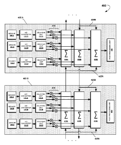
[0028] FIG. 4 shows a block diagram of a beamforming system 400,
according to an
example embodiment. In particular, the beamforming system 400 may include one
or more
modular beamforming devices. As can be seen from FIG. 4, the beamforming
system 400
includes at least two modular beamforming devices 405A and 405B. Each modular
beamforming device 405A, 405B may include a plurality of signal generating
units, which may
consist of a plurality of sensors 105A ¨ 105Z and/or a plurality of A/D
converters 110A ¨ 110Z
operatively coupled thereto. The sensors 105A ¨ 105Z may include microphones,
antennas,
ultrasound receivers, or similar analog or digital electronic devices. The A/D
converters 110A ¨
110Z may be utilized when the sensors 105A ¨ 105Z output analog signals. Thus,
the A/D
converters 110A ¨ 110Z may convert the analog signals into corresponding
digital signals, when
necessary.
[0029] Each modular beamforming device 405A, 405B may further include a
plurality of
delaying units 115A ¨ 115Z, which may be configured to delay digital signals
received from the
A/D converters 110A ¨ 110Z at different times. The signals may be delayed by
predetermined
time periods, adaptively, or dynamically. In the latter case, there can be
utilized a "dynamic
focusing" technique to generate a plurality of "phase shifted" signals delayed
by different time
periods. In the shown example embodiment, the delaying units 115A ¨ 115Z
output three
signals delayed by different time periods. It should be understood, however,
that a different
6
CA 02891617 2015-05-14
WO 2014/081540 PCT/US2013/067278
number of output signals can be generated, each of which may be delayed by any
suitable time
period.
[0030] Furthermore, as shown in FIG. 4, the signals delayed by the
delaying units 115A
¨ 115Z may be conditioned by multipliers 410. Specifically, the multipliers
410 may modify the
signal output by the delaying units 115A ¨ 115Z by applying different
"weights." This
modification may be used to improve signal sensitivity, improve signal-to-
noise ratio, or perform
specific filtering. The weights may be either predetermined, determined
dynamically, or
adaptively selected and applied. In the latter case, the "dynamic apodization"
technique can be
used. In the shown embodiment, there can be three multipliers 410 associated
with every
delaying unit 115A ¨ 115Z, although any other number of multipliers 410 can be
used.
[0031] Still referencing to FIG. 4, the signals output by the multipliers
410 are submitted
to corresponding summers 415A ¨ 415C. Accordingly, there can be three summers
415A ¨
415C, each of which receives signals delayed by delaying units 115A ¨ 115Z.
One of the
summers, e.g. the summer 415C, may be operatively coupled with a post-
processing unit 420
which may perform additional signal processing as described in more detail
below.
[0032] At least two modular beamformers 405A and 405B may be
interconnected
together with the help of one or more connection units such as a connection
unit 425A and a
connection unit 425B. In general, the connection units 425A, 425B may be
configured to
transmit signals from summers of one modular beamformer to summers of another
modular
beamformer. As shown in FIG. 4, the connection unit 425A can operatively
couple the summers
415A in series, such that the signals from one summer 415A of one modular
beamformer is
transmitted to another summer 415A of another modular beamformer in a first
direction. In
addition, as shown in FIG. 4, the connection unit 425A can operatively couple
the summer 415A
with the summer 415C. Similarly, the connection unit 425B can operatively
couple the summers
415B in series, such that the signals from one summer 415B of one modular
beamformer can be
transmitted to another summer 415B of another modular beamformer in a second
direction,
which is opposite to the first direction. In addition, the connection unit
425B can operatively
couple the summer 415B with the summer 415C in each modular beamformer.
[0033] Therefore, as one skilled in the art may recognize, the summer
415C of each
modular beamformer of the system 400 may combine phased signals received from
each
modular beamformer of the system 400. In other words, the resulting phased
array output signal
may be generated by any of the modular beamformers 405A, 405B, and so forth
within the
7
CA 02891617 2015-05-14
WO 2014/081540 PCT/US2013/067278
beamforming system 400. This technique can provide greater flexibility in
configuring
beamforming systems because such systems may be constituted by any number of
modular
beamformers having any number of sensors (or channels). Each modular
beamformer, in turn,
may serve as a "summing unit" for all modular beamformers used in the system,
thereby
providing additional flexibility for design and the use of such systems.
[0034] The post-processing unit 420 may be configured to assist in
combining signals
from the modular beamformers and/or perform any additional signal post-
processing. For
example, the post-processing unit 420 may generate an evaluation signal based
on the resulting
phased array output signal generated by one of the summers 415C. Furthermore,
the post-
processing unit 420 may use additional filtering, weighting, or other signal
modifying
techniques.
[0035] FIG. 5 shows a block diagram of a beamforming system 500,
according to another
example embodiment. In this embodiment, the beamforming system 500 is a scaled
model of the
beamforming system 400. As shown in the figure, the beamforming system 500 may
include
two or more of modular beamformers 505A, 505B, and so forth, which are
interconnected in
parallel. As described above, each modular beamformer 505A, 505B, and so forth
may include a
plurality of sensors 105A ¨ 105Z (not shown), a plurality of A/D converters
110A ¨ 110Z, a
plurality of delaying units 115A ¨ 115Z, a plurality of multipliers 410, a
plurality of summers
515A ¨ 515N, and a post-processing unit 420. In this embodiment, there may be
more than three
summers and more than three multipliers. More specifically, the delaying units
115A ¨ 115Z
may generate N signals from each A/D converter 110A ¨ 110Z by applying a
different delay.
These N signals may be adaptively amplified by N multipliers 410, and then
supplied to N
summers 515A ¨ 515N. Furthermore, as will be recognized by those skilled in
the art, there can
be more than one post-processing unit 420, which may be in communication with
corresponding
summers 515A ¨ 515N.
[0036] One of the summers, specifically the summer 515N, may serve as a
"central"
summer which may combine signals from each modular beamformer 505A, 505B, and
so forth
to generate a phased array output signal. The connection units 525A and 525B
may interconnect
the summers 515A - 515N of various modular beamformers as shown in the FIG. 5,
similarly to
those described above with reference to FIG. 4.
[0037] FIG. 6 shows a block diagram of a beamforming system 600,
according to yet
another example embodiment. In general, this embodiment is similar to the one
described with
8
CA 02891617 2015-05-14
WO 2014/081540 PCT/US2013/067278
reference to FIG. 5 above with the difference being that there is only one
modular beamformer
which may include a post-processing unit 610. In particular, in the embodiment
illustrated in
FIG. 6, only modular beamformer 605A includes the post-processing unit 610,
and thus the
resulting signal is output from this modular beamformer 605A only. It should
be recognized by
those skilled in the art that there can be more than one post-processing unit
420 in modular
beamformer 605A, which may be in communication with corresponding summers 515A
¨ 515N.
[0038] It should be understood by those skilled in the art that modules
of beamforming
systems 400, 500 and 600 as described above with reference to FIGs. 4, 5 and 6
may include
hardware components, software (firmware) components, or a combination thereof
In certain
embodiments, one or more components may be integrated into or implemented as a
single device
such as a chip or microcontroller. For example, the delaying units,
multipliers, and summers
may be implemented by one or more processors or similar computing means.
[0039] FIG. 7 shows an exemplary flow diagram illustrating a method 700
for signal
beamforming, according to one or more embodiments of the present disclosure.
The method 700
may be implemented by beamforming systems as described herein with reference
to FIGs. 4, 5 or
6.
[0040] The method 700 may commence in operation 710 with a plurality of
signal
generation units, such as sensors 105A ¨ 105Z and/or A/D converters 110A ¨
110Z, generating
digital signals. In an example embodiment, the digital signals may include
ultrasound waves.
[0041] In operation 720, a plurality of delaying units 115A ¨ 115Z may
adaptively delay
the digital signals generated by the signal generation units.
[0042] In operation 730, a plurality of multipliers 410 may generate
conditioned digital
signals by adaptively applying one or more weights to the digital signals
output by the plurality
of delaying units 115A ¨ 115Z.
[0043] In operation 740, a plurality of summers (e.g., summers 415A-415C)
may
selectively combine the conditioned digital signals output by the plurality of
multipliers 410 to
generate a phased array output signal.
[0044] In one or more embodiments of the present disclosure, all or some
of the
operations of FIG. 7 may be performed by a computing device, logic,
controller, or processor. It
should be understood that the processes of FIG. 7 are illustrated as logical
flow diagrams, in
9
CA 02891617 2015-05-14
WO 2014/081540 PCT/US2013/067278
which each operation represents a sequence of operations that can be
implemented in hardware,
software, or a combination thereof In the context of software, the operations
can represent
computer-executable instructions stored on one or more non-transitory computer-
readable
storage media that, when executed by one or more processors, perform the
recited operations.
Generally, computer-executable instructions can include routines, programs,
objects,
components, data structures, and the like that perform particular functions or
implement
particular abstract data types. The order in which the operations are
described is not intended to
be construed as a limitation, and any number of the described operations can
be combined in any
order and/or in parallel to implement the processes.
[0045] Thus, the methods and systems for signal beamforming have been
described.
Although the embodiments have been described with reference to specific
example
embodiments, it will be evident that various modifications and changes can be
made to these
example embodiments without departing from the broader spirit and scope of the
present
application. Accordingly, the specification and drawings are to be regarded in
an illustrative
rather than a restrictive sense.