Sélection de la langue

Search

Sommaire du brevet 2893085 

Énoncé de désistement de responsabilité concernant l'information provenant de tiers

Une partie des informations de ce site Web a été fournie par des sources externes. Le gouvernement du Canada n'assume aucune responsabilité concernant la précision, l'actualité ou la fiabilité des informations fournies par les sources externes. Les utilisateurs qui désirent employer cette information devraient consulter directement la source des informations. Le contenu fourni par les sources externes n'est pas assujetti aux exigences sur les langues officielles, la protection des renseignements personnels et l'accessibilité.

Disponibilité de l'Abrégé et des Revendications

L'apparition de différences dans le texte et l'image des Revendications et de l'Abrégé dépend du moment auquel le document est publié. Les textes des Revendications et de l'Abrégé sont affichés :

  • lorsque la demande peut être examinée par le public;
  • lorsque le brevet est émis (délivrance).
(12) Brevet: (11) CA 2893085
(54) Titre français: BROUILLAGE DE POLARISATION DANS DES SYSTEMES INTERFEROMETRIQUES
(54) Titre anglais: POLARIZATION SCRAMBLING IN INTERFEROMETER SYSTEMS
Statut: Octroyé
Données bibliographiques
(51) Classification internationale des brevets (CIB):
  • G01V 8/10 (2006.01)
  • G01N 21/84 (2006.01)
(72) Inventeurs :
  • CHILDERS, BROOKS A. (Etats-Unis d'Amérique)
  • DUNCAN, ROGER GLEN (Etats-Unis d'Amérique)
  • BALAGOPAL, AJIT (Etats-Unis d'Amérique)
  • PROVENZANO, DAN R. (Etats-Unis d'Amérique)
(73) Titulaires :
  • BAKER HUGHES INCORPORATED (Etats-Unis d'Amérique)
(71) Demandeurs :
  • BAKER HUGHES INCORPORATED (Etats-Unis d'Amérique)
(74) Agent: MARKS & CLERK
(74) Co-agent:
(45) Délivré: 2017-11-14
(86) Date de dépôt PCT: 2013-11-01
(87) Mise à la disponibilité du public: 2014-06-12
Requête d'examen: 2015-05-29
Licence disponible: S.O.
(25) Langue des documents déposés: Anglais

Traité de coopération en matière de brevets (PCT): Oui
(86) Numéro de la demande PCT: PCT/US2013/068068
(87) Numéro de publication internationale PCT: WO2014/088738
(85) Entrée nationale: 2015-05-29

(30) Données de priorité de la demande:
Numéro de la demande Pays / territoire Date
13/707,979 Etats-Unis d'Amérique 2012-12-07

Abrégés

Abrégé français

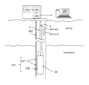
La présente invention concerne un système et un procédé permettant d'obtenir et de traiter des balayages de sortie d'interféromètre. Le système de détection à interféromètre de l'invention comprend un laser accordable servant à émettre un signal de transmission et un brouilleur de polarisation servant à produire un changement d'état de polarisation sur le signal de transmission. Le système comprend également un interféromètre servant à produire un balayage de sortie sur la base du signal de transmission présentant le changement d'état de polarisation et un processeur servant à traiter le balayage de sortie.


Abrégé anglais


A system and method to
obtain and process interferometer output
scans is described. The interferometer-based
sensor system includes a
tunable laser to transmit a transmit signal
and a polarization scrambler to produce
a polarization state change on the
transmit signal. The system also includes
an interferometer to provide an
output scan based on the transmit signal
with the polarization state change and a
processor to process the output scan.


Revendications

Note : Les revendications sont présentées dans la langue officielle dans laquelle elles ont été soumises.


What is claimed is:
1. An interferometer-based sensor system, comprising:
a tunable laser configured to transmit a transmit signal;
a polarization scrambler configured to produce a polarization state change on
the transmit signal prior to each scan such that the polarization state of the
transmit signal for
one scan differs from the polarization state of the transmit signal for
another scan;
an interferometer configured to provide an output scan based on the transmit
signal with the polarization state change for each scan, the interferometer
comprising one or
more fiber Bragg gratings (FBGs) and a reference reflector and the output scan
resulting from
interference between a reflection signal from the reference reflector and a
reflection signal from
one of the one or more FBGs; and
a processor configured to process the output scan.
2. The system according to claim 1, wherein the polarization state change
is
random, and, over a period of time, polarization states are uniform.
3. The system according to claim 1 or 2, wherein the processor processes a
number of output scans at a time, the number being received over a period of
time.
4. The system according to claim 3, wherein the processor performs a
weighted
average on the number of output scans, each weighting being based on an
amplitude of the
respective output scan.
5. The system according to claim 3, wherein the processor performs a
weighted
average on the number of output scans, each weighting being based on a signal-
to-noise ratio of
the respective output scan.
6. The system according to any one of claims 3 to 5, wherein the processor
uses a
sliding window to select the number of output scans.

7. A method of obtaining and processing interferometer output scans, the
method
comprising:
arranging a polarization scrambler between a tunable laser and an
interferometer, the interferometer comprising one or more fiber Bragg gratings
(FBGs) and a
reference reflector;
changing a polarization state of each signal from the tunable laser with the
polarization scrambler to generate each polarization scrambled signal, the
polarization state of
one of the polarization scrambled signals being different from the
polarization state of another
of the polarization scrambled signals;
receiving each of the output scans from the interferometer based on each of
the
polarization scrambled signals for each scan, each of the output scans
resulting from
interference between a reflection signal from the reference reflector with a
reflection signal
from one of the one or more FBGs; and
processing the output scans.
8. The method according to claim 7, wherein the changing the polarization
state
includes generating a uniform sampling of polarization states over time.
9. The method according to claim 7 or 8, wherein the processing the output
scans
includes determining a weighted average of a number of the output scans.
10. The method according to claim 9, wherein the determining the weighted
average includes weighting each of the output scans of the number of the
output scans based on
an amplitude of the respective output scan.
11. The method according to claim 9, wherein the determining the weighted
average includes weighting each of the output scans of the number of the
output scans based on
a signal-to-noise ratio of the respective output scan.
12. The method according to any one of claims 9 to 11, wherein the
determining
the weighted average is done in a sliding window fashion with one of the
number of the output
scans being different in each of the weighed averages.
6

Description

Note : Les descriptions sont présentées dans la langue officielle dans laquelle elles ont été soumises.


CA 02893085 2016-11-04
POLARIZATION SCRAMBLING TN INTERFEROMETER SYSTEMS
BACKGROUND
[0001/0002] In downhole exploration and geologic resource recovery, the
ability to obtain
information about the conditions of the environment and the status of the
equipment downhole can
be helpful in making decisions. Optical frequency domain reflectometers (OFDR)
are among the
types of sensors used downhole. OFDR is an interferometer-based system that
relies on the
interference between signals generated or reflected by individual sources
based on an optical
signal. When the polarizations of the two signals are parallel to each other
(0 degree angle
between them), this provides maximum interference. However, when the two
signals have
orthogonal polarizations (90 degree angle between them), then there is no
interference between the
signals and, as a result, no signal from the interferometer. This results in
noisy output from the
OFDR system, which cannot know when the interferometer signal is null. Thus,
an apparatus and
method to ensure performance of the interferometer-based systems would be
appreciated in the
industry.
SUMMARY
[0003] According to one aspect of the invention, an interferometer-based
sensor system,
comprising: a tunable laser configured to transmit a transmit signal; a
polarization scrambler
configured to produce a polarization state change on the transmit signal prior
to each scan such
that the polarization state of the transmit signal for one scan differs from
the polarization state of
the transmit signal for another scan; an interferometer configured to provide
an output scan based
on the transmit signal with the polarization state change for each scan, the
interferometer
comprising one or more fiber Bragg gratings (FBGs) and a reference reflector
and the output scan
resulting from interference between a reflection signal from the reference
reflector and a reflection
signal from one of the one or more FBGs; and a processor configured to process
the output scan.
[0004] According to another aspect of the invention, a method of obtaining and

processing interferometer output scans, the method comprising: arranging a
polarization scrambler
between a tunable laser and an interferometer, the interferometer comprising
one or more fiber
Bragg gratings (FBGs) and a reference reflector; changing a polarization state
of each signal from
the tunable laser with the polarization scrambler to generate each
polarization scrambled signal,
the polarization state of one of the polarization scrambled signals being
different from the
polarization state of another of the polarization scrambled signals; receiving
each of the output
scans from the interferometer based on each of the polarization scrambled
signals for each scan,
each of the output scans resulting from interference between a reflection
signal from the reference
reflector with a reflection signal from one of the one or more FBGs; and
processing the output
scans.
1

CA 02893085 2015-05-29
WO 2014/088738 PCT/US2013/068068
BRIEF DESCRIPTION OF THE DRAWINGS
[0005] Referring now to the drawings wherein like elements are numbered alike
in
the several Figures:
[0006] FIG. 1 is a cross-sectional illustration of a borehole including a
distributed
acoustic sensor system according to an embodiment of the invention;
[0007] FIG. 2 is a block diagram of an OFDR network including a polarization
scrambler according to an embodiment of the invention;
[0008] FIG. 3 illustrates an exemplary processing scheme for the OFDR network
shown in FIG. 2 according to an embodiment of the invention; and
[0009] FIG. 4 is a process flow diagram of an exemplary method 400 to obtain
interferometer output using polarization scrambling according to embodiments
of the
invention.
DETAILED DESCRIPTION
[0010] Any interferometer-based sensor system (e.g., optical frequency domain
reflectometer (OFDR)) relies on the interference among signals generated or
reflected by
individual sources to generate the interferometer signal used to determine
information of
interest. Embodiments of the invention described herein ensure reliable
interferometer
signals for accurate measurements. While OFDR systems are used as exemplary
interferometer-based systems for purposes of explanation, the scrambler and
scrambling
method detailed below applies, as well, to other interferometer-based systems.
[0011] FIG. 1 is a cross-sectional illustration of a borehole 1 including an
interferometer-based sensor system according to an embodiment of the
invention. A
borehole 1 penetrates the earth 3 including a formation 4. A set of tools 10
may be lowered
into the borehole by a carrier 2. In embodiments of the invention, the carrier
may be an
armored wireline. In measure-while-drilling (MWD) embodiments, the carrier 2
may be a
drill string, and a drill would be included below the tools 10. Information
from the sensors
and measurement devices included in the set of tools 10 may be telemetered to
the surface for
processing by the surface processing system 130. The interferometer-based
sensor system
includes an optical fiber 110. In the exemplary embodiment shown in FIG. 1,
the optical
fiber 110 includes fiber Bragg gratings (FBGs) 117 and a reference reflector
118 that
comprise an interferometer 115. A tunable laser 120 is shown at the surface of
the earth 3 in
FIG. 1. The polarization scrambler 140 that acts on the tunable laser 120
output before the
2

CA 02893085 2015-05-29
WO 2014/088738 PCT/US2013/068068
optical network 145 transmits the signal to the interferometer 115 is
discussed in detail with
reference to FIG. 2 below.
[0012] FIG. 2 is a block diagram of an OFDR network 200 including a
polarization
scrambler 140 according to an embodiment of the invention. The polarization
scrambler 140
acts on the signal from the tunable laser 120 being sent to the interferometer
115. By varying
the polarization state of the signal input to the interferometer 115, a higher
percentage of non-
null interferometer signals (signals not being perpendicular to each other)
are ensured as
interferometer output. The output of the tunable laser 120 may itself have a
different
polarization state over time. However, this variation in the signal from the
tunable laser 120
is not certain or predictable. The polarization scrambler 140, unlike the
tunable laser 120,
can be made to randomly vary the polarization state of the tunable laser 120
output over time
before it reaches the interferometer. The possible polarization states
achieved by the
polarization scrambler 140 may be mapped over time and would indicate uniform
sampling
that could be represented by a Poincare sphere, for example. Even though the
tunable laser
120 changes polarization states over time, it would not achieve this uniform
sampling of
polarization states. In alternate embodiments, the polarization scrambler 140
may change
polarization state of the tunable laser 120 output in a predefined pattern.
[0013] FIG. 3 illustrates an exemplary processing scheme for the OFDR network
200
shown in FIG. 2 according to an embodiment of the invention. The polarization
state of the
tunable laser 120 output is randomly varied prior to each scan. The output 310
of the
interferometer 115 for each scan is averaged over a number of scans. In the
embodiment
shown in FIG. 3, 5 outputs 310 (the result of 5 scans of the tunable laser 120
randomly varied
in polarization state by the polarization scrambler 140) are averaged at a
time in a sliding
window fashion. That is, the first 5 outputs 310a ¨ 310e are averaged as 320a,
then the first
scan 310a is dropped and the next scan 310f is included in the next average
320b. The
sliding window average continues in this fashion. The average may be a
weighted average
such that larger amplitude interferometer 115 outputs 310 are weighted higher
than lower
amplitude outputs 310. Weighting may be based on other factors like signal-to-
noise ratio,
for example. The averaging increases the signal-to-noise ratio (SNR) of the
interferometer
115 output 310. In alternate embodiments, the exemplary processing shown by
FIG. 3 may
be varied in one or more ways. For example, a different number of outputs 310
may be
averaged at a time or a different weighting scheme may be used for the outputs
310 to
provide the weighted average 320.
3

CA 02893085 2015-05-29
WO 2014/088738 PCT/US2013/068068
[0014] FIG. 4 is a process flow diagram of an exemplary method 400 to obtain
interferometer output using polarization scrambling according to embodiments
of the
invention. At block 410, arranging the polarization scrambler 140 in the
interferometer
system may include, for example, arranging the polarization scrambler 140
between the
tunable laser 120 and the interferometer 115 as shown in FIG. 2 for the
exemplary OFDR
network 200. Obtaining scans using signals with varied polarization state at
block 420
includes the polarization scrambler 140 randomly or in a predefined pattern
changing the
polarization state of the tunable laser 120 output. Block 420 also includes
receiving the
resulting interferometer 115 output scans. Processing the scans at block 430
may include, for
example, weighting and averaging a particular number of interferometer 115
output scans at a
time in a sliding window fashion, as discussed with reference to FIG. 3.
[0015] While one or more embodiments have been shown and described,
modifications and substitutions may be made thereto without departing from the
spirit and
scope of the invention. Accordingly, it is to be understood that the present
invention has been
described by way of illustrations and not limitation.
4

Dessin représentatif
Une figure unique qui représente un dessin illustrant l'invention.
États administratifs

Pour une meilleure compréhension de l'état de la demande ou brevet qui figure sur cette page, la rubrique Mise en garde , et les descriptions de Brevet , États administratifs , Taxes périodiques et Historique des paiements devraient être consultées.

États administratifs

Titre Date
Date de délivrance prévu 2017-11-14
(86) Date de dépôt PCT 2013-11-01
(87) Date de publication PCT 2014-06-12
(85) Entrée nationale 2015-05-29
Requête d'examen 2015-05-29
(45) Délivré 2017-11-14

Historique d'abandonnement

Il n'y a pas d'historique d'abandonnement

Taxes périodiques

Dernier paiement au montant de 263,14 $ a été reçu le 2023-10-19


 Montants des taxes pour le maintien en état à venir

Description Date Montant
Prochain paiement si taxe générale 2024-11-01 347,00 $
Prochain paiement si taxe applicable aux petites entités 2024-11-01 125,00 $

Avis : Si le paiement en totalité n'a pas été reçu au plus tard à la date indiquée, une taxe supplémentaire peut être imposée, soit une des taxes suivantes :

  • taxe de rétablissement ;
  • taxe pour paiement en souffrance ; ou
  • taxe additionnelle pour le renversement d'une péremption réputée.

Les taxes sur les brevets sont ajustées au 1er janvier de chaque année. Les montants ci-dessus sont les montants actuels s'ils sont reçus au plus tard le 31 décembre de l'année en cours.
Veuillez vous référer à la page web des taxes sur les brevets de l'OPIC pour voir tous les montants actuels des taxes.

Historique des paiements

Type de taxes Anniversaire Échéance Montant payé Date payée
Requête d'examen 800,00 $ 2015-05-29
Le dépôt d'une demande de brevet 400,00 $ 2015-05-29
Taxe de maintien en état - Demande - nouvelle loi 2 2015-11-02 100,00 $ 2015-05-29
Taxe de maintien en état - Demande - nouvelle loi 3 2016-11-01 100,00 $ 2016-10-07
Taxe finale 300,00 $ 2017-09-28
Taxe de maintien en état - Demande - nouvelle loi 4 2017-11-01 100,00 $ 2017-10-06
Taxe de maintien en état - brevet - nouvelle loi 5 2018-11-01 200,00 $ 2018-10-11
Taxe de maintien en état - brevet - nouvelle loi 6 2019-11-01 200,00 $ 2019-10-22
Taxe de maintien en état - brevet - nouvelle loi 7 2020-11-02 200,00 $ 2020-10-21
Taxe de maintien en état - brevet - nouvelle loi 8 2021-11-01 204,00 $ 2021-10-20
Taxe de maintien en état - brevet - nouvelle loi 9 2022-11-01 203,59 $ 2022-10-24
Taxe de maintien en état - brevet - nouvelle loi 10 2023-11-01 263,14 $ 2023-10-19
Titulaires au dossier

Les titulaires actuels et antérieures au dossier sont affichés en ordre alphabétique.

Titulaires actuels au dossier
BAKER HUGHES INCORPORATED
Titulaires antérieures au dossier
S.O.
Les propriétaires antérieurs qui ne figurent pas dans la liste des « Propriétaires au dossier » apparaîtront dans d'autres documents au dossier.
Documents

Pour visionner les fichiers sélectionnés, entrer le code reCAPTCHA :


Pour visualiser une image, cliquer sur un lien dans la colonne description du document. Pour télécharger l'image (les images), cliquer l'une ou plusieurs cases à cocher dans la première colonne et ensuite cliquer sur le bouton "Télécharger sélection en format PDF (archive Zip)" ou le bouton "Télécharger sélection (en un fichier PDF fusionné)".

Liste des documents de brevet publiés et non publiés sur la BDBC .

Si vous avez des difficultés à accéder au contenu, veuillez communiquer avec le Centre de services à la clientèle au 1-866-997-1936, ou envoyer un courriel au Centre de service à la clientèle de l'OPIC.


Description du
Document 
Date
(yyyy-mm-dd) 
Nombre de pages   Taille de l'image (Ko) 
Abrégé 2015-05-29 2 63
Revendications 2015-05-29 2 70
Dessins 2015-05-29 4 30
Description 2015-05-29 4 202
Dessins représentatifs 2015-05-29 1 12
Page couverture 2015-06-30 1 36
Description 2016-11-04 4 209
Taxe finale 2017-09-28 2 71
Dessins représentatifs 2017-10-19 1 6
Page couverture 2017-10-19 1 38
PCT 2015-05-29 7 242
Cession 2015-05-29 6 151
Correspondance reliée au PCT 2015-08-04 3 92
Demande d'examen 2016-05-11 3 218
Modification 2016-11-04 7 308
Revendications 2016-11-04 2 68