Note : Les descriptions sont présentées dans la langue officielle dans laquelle elles ont été soumises.
Apparatus and Methods to Find a Position in an Underground Formation
Technical Field
The present invention relates generally to apparatus and method for
making measurements related to oil and gas exploration.
Background
In drilling wells for oil and gas exploration, understanding the structure
and properties of the associated geological formation provides information to
aid
such exploration. Data to provide the information may be obtained using
sensors
located in an underground formation at large distances from the surface.
Knowing the position of these sensors in the underground formation can be used
to formulate the information for exploration. Systems and techniques to
determine the position of sensors in the underground formation can enhance the
analysis process associated with a drilling operation.
Summary
In accordance with a broad aspect, there is provided a method,
comprising: receiving signals from a receiver in an underground formation in
response to signals generated from three or more transmitting sources, each of
the three or more transmitting sources located at a known position, at least
one
transmitting source of the three or more transmitting sources separated from
and
mounted on a structure different from at least one other transmitting source
of
the three or more transmitting sources; and processing the received signals,
using
an inversion process based on the signals generated from the three or more
transmitting sources, to determine the position and an orientation of the
receiver.
In accordance with another broad aspect, there is provided a machine-
readable storage device having instructions stored thereon. When performed by
a
machine, the instructions cause the machine to perform operations to: receive
signals from a receiver in an underground formation in response to signals
generated from three or more transmitting sources, each of the three or more
transmitting sources located at a known position, at least one transmitting
source
of the three or more transmitting sources separated from and mounted on a
structure different from at least one other transmitting source of the three
or
1
CA 2893747 2018-03-28
more transmitting sources; and process the received signals, using an
inversion
process based on the signals generated from the three or more transmitting
sources, to determine the position and an orientation of the receiver.
In accordance with a further broad aspect, there is provided a system,
comprising: three or more transmitting sources, each of the sources located at
a
known position, at least one transmitting source of the three or more
transmitting
sources separated from and mounted on a structure different from at least one
other transmitting source of the three or more transmitting sources; a control
unit
arranged to control generation of signals from the three or more transmitting
sources; a receiver in an underground formation, the receiver operable to
receive
signals in response to the generation from the three or more transmitting
sources;
and a processing unit arranged to process the received signals, using an
inversion
process based on the signals generated from the three or more transmitting
sources, to determine the position and an orientation of the receiver.
Brief Description of the Drawings
Figure 1 shows an example placement of transmitters and a receiver,
which placement can be used to determine the position of the receiver, in
accordance with various embodiments.
Figure 2 shows a simulation setup for the analysis of the effect of
frequency, in accordance with various embodiments.
Figures 3A-B show depth vs. voltage levels of received signals for
different frequencies for the simulation setup of Figure 2, in accordance with
various embodiments.
Figures 4A-B show depth vs. voltage levels of received signals for
varying formation resistivities at a fixed operation frequency for the
simulation
setup of Figure 2, in accordance with various embodiments.
Figures 5A-B show depth vs. voltage levels of received signals for
varying formation resistivities at another fixed operation frequency for the
simulation setup of Figure 2, in accordance with various embodiments.
Figure 6 shows features of an example inversion scheme to determine the
position of a receiver in an underground formation, in accordance with various
embodiments.
lA
CA 2893747 2018-03-28
CA 02893747 2015-06-03
WO 2014/105087
PCT/US2012/072326
Figure 7 shows features of an example of a constrained inversion scheme
to determine the position of a receiver in an underground formation, in
accordance with various embodiments.
Figure 8 shows features of a simulation to verify an inversion scheme
and to analyze the accuracy obtained in determining the position of one or
more
sensors for different system configurations, in accordance with. various
embodiments.
Figure 9 shows a simulation geometry for a positioning system with two
x-directed transmitters at the surface, in accordance with various
embodiments.
Figures 10A-E show results of a Monte Carlo simulation for the
simulation geometry of Figure 9, in accordance with various embodiments.
Figures 11A-E show results of a Monte Carlo simulation for the
positioning system of figure 9 where a second receiver is used, whose position
is
constrained with respect to a first receiver, in accordance with various
embodiments.
Figure 12 shows a simulation geometry for a two transmitter positioning
system, where one of the transmitters is underground, in accordance with
various
embodiments.
Figures 13A-E show results of a Monte Carlo simulation for the
positioning system of Figure 12, in accordance with various embodiments.
Figure 14 shows a simulation geometry for a positioning system with
four triad type transmitters, in accordance with various embodiments.
Figures 15A-E shows results of a Monte Carlo simulation for the
positioning system of Figure 14, in accordance with various embodiments.
Figure 16 shows a two-dimensional example with transmitters on the
surface and a receiver underground to illustrate a method to find the position
of
the receiver relative to the sources from the known orientations of the
sources, in
accordance with various embodiments.
Figure 17 shows a two-dimensional example with transmitters on the
surface and a receiver underground in which the receiver has a reference
direction, in accordance with various embodiments.
Figure 18 shows a three-dimensional example with transmitters on the
surface and a receiver underground in which the receiver has no reference
2
CA 02893747 2015-06-03
WO 2014/105087
PCT/US2012/072326
direction, in accordance with various embodiments.
Figures 19A-B show Monte Carlo simulation results using a semi-
analytical solution for the positioning system shown in Figure 9, in
accordance
with various embodiments.
Figure 20 shows an electric field at the receiver, due to a magnetic
dipole, that is normal to the plane where receiver and transmitter are
located, in
accordance with various embodiments.
Figure 21 shows a simulated system for electric field based positioning
system, in accordance with various embodiments.
Figures 22A-C show Monte Carlo simulation results using an electric
field based positioning system of Figure 21, in accordance with various
embodiments.
Figure 23 depicts a block diagram of features of an example system to
find a position in an underground formation, in accordance with various
embodiments.
Detailed Description
The following detailed description refers to the accompanying drawings
that show, by way of illustration and not limitation, various embodiments in
which the invention may be practiced. These embodiments are described in
sufficient detail to enable those skilled in the art to practice these and
other
embodiments. Other embodiments may be utilized, and structural, logical, and
electrical changes may be made to these embodiments. The various
embodiments are not necessarily mutually exclusive, as some embodiments can.
be combined with one or more other embodiments to form new embodiments.
The following detailed description is, therefore, not to be taken in a
limiting
sense.
In various embodiments, systems and methods to find the position of an
underground receiver can include locating the position of the receiver, or
receivers, from measurements taken by the receivers and the known positions of
the sources that generate the signals for the measurements. Sources can be
used
that are placed at known positions either at the surface or below the surface
of
the earth with the receiver or receivers located underground. The position of
3
CA 02893747 2015-06-03
WO 2014/105087
PCT/US2012/072326
underground receiver(s) from the measurements of the signals, generated by a
number of transmitting sources whose positions are known precisely, may be
determined.
Electromagnetic type transmitting sources and receivers can be used in
systems to determine a position underground. Such transmitting sources can
include, but are not limited to, dipole transmitters, sources generating large
distribution of current aboveground or near ground that generate
electromagnetic
fields below ground, where the electromagnetic fields measurable at the
receiver,
or other sources that can generate a signal measurable at a receiver deep in
an
underground formation. Dipoles of sources can be oriented in a direction
perpendicular to the area of interest, where the area of interest includes a
receiving source to be located. This orientation can account for a null point
along the direction of the dipole. Transmitting sources can be realized by one
or
more triad transmitters. A triad transmitter is a structure having three
transmitting sources at the same location, where the position or orientation
of the
three transmitting sources is different from each other. The three
transmitting
sources of the triad can be mounted on the same structure at a given location.
Transmitting sources aboveground or near ground can be operated to generate
signals having a low frequency to penetrate deeply underground such that the
signals are measurable in an underground volume extending from a hundred feet
to thousands feet in depth and from a hundred feet to thousands of feet across
the
depth. Alternatively, other types of transmitters used in oilfield exploration
industry, such as. but not limited to, acoustic sensors and seismic sensors,
can be
used in systems to determine a position underground. The number of
transmitting sources may include three or more transmitting sources. In an
embodiment, three transmitting sources can be realized by a single triad
transmitter.
The receiver or receivers can be controlled by electronics disposed
underground. In addition, a processing unit can be located downhole to
analysis
the signals received by the receiver. The processing unit can be realized by
electronics integrated with the receiver, where the information concerning the
known locations of the transmitting sensors is stored with the electronics
along
with instructions to process the signals. The processing unit can be realized
by
4
CA 02893747 2015-06-03
WO 2014/105087
PCT/US2012/072326
electronics disposed on the structure on which the receiver is disposed and
separated from the receiver. The processing unit and receiver control located
downhole can allow for automated geosteering. Alternatively, the processing
unit can be located at the surface, responsive to receiving the signals or
data
regarding the signals from the receiver.
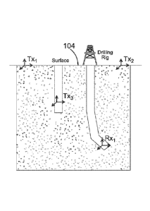
Figure 1 shows an example embodiment of placement of transmitters and
a receiver, which placement can be used to determine the position of the
receiver. In Figure 1, three transmitters, denoted as Txj, Tx2, and Tx, are
illustrated, as an example, in different locations with respect to a receiving
sensor, Rx1. Tx] and Tx2 are on surface 104, while 'Fx3 is underground inside
a
well different from the one in which Rxi is disposed. This figure is a 2-
dimensional (.2D) figure, shown for illustration purposes, in which the
transmitters line in the same plane. In various embodiments, transmitting
sources used to locate the position of a receiving sensor lie in a plane
common to
no more than two transmitters and the receiver sensor. With the transmitting
sensors satisfying this condition, better resolution can be obtained in the
received
signals in a measurement process. In addition, the number of transmitters, the
number or receivers, or the number of transmitters and receivers can be
increased to improve resolution.
The number of transmitters and transmitter locations can also be
optimized using known optimization techniques, depending on the application.
However, in the discussion of embodiments, the effects of the number of
transmitters and their locations are analyzed using numerical modeling
results.
Receiver sensors and transmitters were selected to be triads antennas, as
illustrated in Figure 1, in simulations to improve inversion accuracy,
although
that is not necessary for the operation of embodiments of methods to determine
a
position in an underground formation. As shown in Figure 1, transmitting
sources Txi. Tx2, and Tx.3 structured as three triads can provide 9
transmitting
sources at three locations, with 9 positions or orientations. Receiving
sensor,
Rxj, can also be structured as a triad receiving sensor having three receivers
at
one location with three positions or orientations.
Increasing the number of transmitting sources with each transmitting
source at a known location can increase the amount of information used to
5
CA 02893747 2015-06-03
WO 2014/105087
PCT/US2012/072326
determine the position of a receiver or receivers in underground formations.
In
addition, the transmitting sources are not limited to using the same type of
transmitting source. For example, arrangements can include two triad
transmitters among three or more transmitters distributed over a significantly
large region. Other arrangements can include a transmitting source structured
as
a circuit distributed over a significantly large region on the surface or near
the
surface. The circuit can include a closed loop having a current-carrying wire,
where the current-carrying wire is at a known position and the current-
carrying
wire is arranged along a straight-line path such that signals received at the
receiver from the closed loop are negligible from portions of the closed loop
that
follow a path different from the straight-line path. The signal at the
receiver can
be primarily provided by this single current-carrying wire with the other
portions
of the circuit that close the loop located at such distances from the receiver
that
signals from these other portions are effectively attenuated prior to the
receiver.
Alternatively, a transmitting source can be structured as a circuit having a
closed
loop with a number of current-carrying wires with each current-carqing wire
being at a known position and arranged along a straight-line path such that
signals received at the receiver from the closed loop are negligible from
portions
of the closed loop that follow a path different from these respective straight-
line
paths. The received signals at the receiver can be processed based on a model
of
the number of current-carrying wires and their corresponding straight-line
paths.
Low frequency electromagnetic waves can penetrate deeply below the
surface of the earth. By using low frequency sources (f<10Hz), the fields
generated by the sources will be measurable at positions buried deeply
underground. In an embodiment, low frequency sources having a frequency less
than or equal to 50 Hz can be used. A receiver placed in a borehole under the
surface can measure the signals generated by the sources. These signals from
each one of the sources can. be processed to find the distance, orientation,
or both
distance and orientation. In various embodiments, position determination at
depths as large as 10,000 meters may be performed.
A first consideration includes the effect of frequency on the signals that
penetrate the formation. As frequency increases, attenuation underground
increases such that, at higher frequencies, attenuation is more severe and
could
6
CA 02893747 2015-06-03
WO 2014/105087
PCT/US2012/072326
reduce signals below the noise level. Another factor to consider is that
higher
frequencies are also more sensitive to the formation, which can significantly
affect the received signal. That is, at higher frequencies, the solution for
the
position of a receiver(s) would be sensitive to the parameters of the complex
and
in most cases not accurately known formation information. Example
embodiments of methods to determine a position underground can. be performed
under a single frequency operation. However, in other embodiments, features of
methods to determine a position underground can be performed under a multi-
frequency operation.
Figure 2 shows a simulation setup for the analysis of the effect of
frequency. To analyze the effect of frequency, the variation of the signal
level
with depth is computed as a function of frequency when a single transmitter is
present. Transmitter and receiving sensor were simulated as coil antennas with
their normal parallel to the radial direction of earth. Henceforth, the axis
normal
to the surface of earth will be denoted as z-axis. With this convention, the
simulated case shows the ZZ-coupling. Other orthogonal components (XX-
coupling and YY-coupling) show similar characteristics and are not shown.
In this simulation, receiving sensor Rx is directly below the transmitter
Tx. For illustration purposes, both the receiver and transmitter coils are
assumed
to have a unit area with 400 turns each and the transmitter is assumed to
carry 25
A current. Design parameters can vary as dictated by engineering concerns for
a
given application. However, to be able to transmit signal to such great
depths,
transmitted power level should be high and the receiving sensor structured as
a
highly sensitive receiver. This concern for power level may also make putting
transmitters on the surface 204 more practical than cases where some or all of
the transmitters are under ground. Formation parameters used in the simulation
are also shown in Figure 2. A somewhat worst-case scenario with a conductive
formation of resistivity, Rf, equal. to 1 11-m was considered. Relative
permittivity (6,) and permeability (nr) were selected as 5 and 1,
respectively.
Figures 3A-B show depth vs. voltage levels of received signals for
different frequencies for the simulation setup of Figure 2. Figure 3A shows
the
change of the absolute value of the voltage with depth for four different
frequencies, and Figure 3B shows the change of the phase of the voltage with
7
CA 02893747 2015-06-03
WO 2014/105087
PCT/US2012/072326
depth for the four different frequencies. Curves 342, 344, 346, and 348 show
depth as a function of the absolute value of voltage at frequencies of 0.01
Hz, 0.1
Hz, 1 Hz, and 10 Hz, respectively. Curves 352, 354, 356, and 358 show depth as
a function of the phase of the voltage at frequencies of 0.01 Hz, 0.1 Hz, 1
Hz,
and 10 Hz, respectively. For 1Hz and 10 Hz, signal quickly attenuates. Wrap
around in the phase can also be seen which can. make the inversion difficult.
In
comparison, as the frequency gets lower, signal attenuation becomes less of a
problem. However, for these lower frequencies, initial strength of the signal
is
already low. Thus, even for 0.01 Hz and 0.1 Hz, the voltage level goes to as
low
as 10 fem.toVolts at 10,000 m for the simulated transmitter and receiver
configurations. Results suggest that for the parameters used there is little
improvement in attenuation for frequencies lower than 0.1 Hz. Thus, in other
simulations discussed herein, the frequency of operation was assumed to be 0.1
Hz.
Figures 4A-B show depth vs. voltage levels of received signals for
varying formation resistivities at a fixed operation frequency. To analyze the
effect of formation resistivity, the same setup shown in Figure 2 was used
with
the frequency set to a constant 0.1 Hz and the formation resistivity varied
between 0.1 11-m to 100 0-m. Curves 442, 444, 446, and 448 show depth as a
function of the absolute value of voltage at formation resistivities of 0.1
1
fl-rn, 10 fl-m, and 100 CI-m, respectively. Curves 452, 454, 456, and 458 show
depth as a function of the phase of the voltage at formation resistivities of
0.1 O-
m, I 12-m, 10 I2-m, and 100 111-m, respectively. Effect of formation
resistivity
on the received signal can be seen to be small except for extremely conductive
formations. Thus, this effect can be neglected, or it can be eliminated using
a
basic correction scheme. Nevertheless, for examples discussed herein,
formation
resistivity was assumed to be exactly known.
Figures 5A-B show depth vs. voltage levels of received signals for
varying formation resistivities at another fixed operation frequency, in
accordance with various embodiments. The same setup shown in Figure 2 was
used with the frequency set to a constant 0.01 Hz and the formation
resistivity
varied between 0.1 0-m to 100 fl-m. Curves 542, 544, 546, and 548 show depth
as a function of the absolute value of voltage at formation resistivities of
0.1 a-
8
CA 02893747 2015-06-03
WO 2014/105087
PCT/US2012/072326
m, 1 fl-m, 10 fl-m, and 100 a-m, respectively. Curves 546 and 548 overlap
such that the differences are not discernible at the scales of Figure 5A.
Curves
552, 554, 556, and 558 show depth as a function of the phase of the voltage at
formation resistivities of 0.1 Ll-m, I LI-m, 10 S/-m, and 100 0-m,
respectively.
Results for 0.01 Hz shown in Figure 5 exhibit very little dependence on the
formation resistivity for the depth range considered. However, such a low
frequency may cause difficulties in an implementation of the system hardware.
Figure 6 shows features of an example inversion scheme to determine the
position of a receiver in an underground formation. This inversion scheme
demonstrates how the position of the receiving sensor may be determined using
an array of transmitters at previously known locations. At 610, the
measurement
of signals due to N different transmitters at the receiver is acquired. These
signals are combined into a column vector, denoted as V, at 620. Although a
single receiver relative to N transmitters is discussed at 610 and 620, more
complicated measurements can be considered in a similar or identical manner.
For example, if receivers or transmitters are multi-component, each individual
entry (VT,,Rõ) becomes a vector with individual components as the element of
the
vector. Examples of such receivers and transmitters include triad receivers
and
triad transmitters. If there are multiple frequencies, results of these
measurements may be appended to the measurement vector and so on. Once this
voltage is obtained, it may be further processed depending on the application.
For example, if signal from one of the transmitters is too strong compared to
the
others, amplitudes of received signal from different transmitters may be
normalized to ascertain that weight of each transmitter in the inversion is
same.
In the inversion scheme, the determination of the position and the
direction of the receiving sensor(s) is the object of interest. Thus,
parameters of
interest are denoted as the location of the receiver sensor (x, y, z), its
azimuth
(0), and its elevation angle (9). At 630, an initial guess of the location and
direction parameters (x', y', z', 0', 9') is made. The signal corresponding to
an
initial guess of the location and direction parameters (x', y', z', 0', 9') is
simulated using a forward model, which is denoted as V' at 640. A.s in every
inversion scheme, an accurate forward model that relates parameters to be
inverted to the measured signal is used in this method.
9
CA 02893747 2015-06-03
WO 2014/105087
PCT/US2012/072326
At 650, the norm of the difference between V and V' is compared to a
threshold. If the norm of the difference between V and V' is lower than a
predetermined threshold, the processing may stop and the processed parameters
(x', y', z', 0', 9') may be deemed to be accurate approximations to the true
parameters (x, y, z, 0, 9), at 660. Other convergence criteria may also be
applied
in this step.
If convergence is not satisfied, an iteration number can be increased by
one, at 670. To prevent, for example, infinite simulations for cases where no
solution below the threshold is possible such as at highly noisy environments,
or
to restrict the simulation time, the number of iterations may be compared with
a
previously set maximum iteration number, at 680. If the maximum number of
iterations is reached, the processing may stop with the latest guess, or a
previous
guess that minimized the error, returned as the answer, at 685. Otherwise, the
parameter guess vector is updated at 690, V' is simulated again, at 640, based
on
this guess and the above process of comparing the process signal with the
measured signal and subsequent comparisons can be repeated. The update of the
guess vector may be based on the calculation of a gradient that minimizes the
error.
Alternative inversion schemes may be used with equal success. Such
inversion schemes can include using a lookup table. Another alternative
inversion scheme can include applying a brute force search method that tries a
large number of possible input combinations and selects the one that minimizes
the error between the measured data and the forward model. Alternative
inversion schemes are not limited to these alternatives, but may include other
alternative inversion schemes or combinations thereof.
Figure 7 shows features of an example of a constrained inversion scheme
to determine the position of a receiver in an underground formation, in
accordance with various embodiments. A constraint may be applied as one of a
number of different techniques may be employed to reduce the error in
inversion. One such technique is the addition of a second sensor whose
position
relative to the first sensor is exactly known. Although these two sensors will
have to be close to each other in the electrical sense, thus providing little
independent information, the fact that the noise at separate sensors should be
CA 02893747 2015-06-03
WO 2014/105087
PCT/US2012/072326
mostly independent will improve the inversion accuracy. Inversion in this case
can be similar to the inversion with a single receiver associated with Figure
6.
At 710, the measurement of signals due to N different transmitters at the
two receivers is acquired. These signals are combined into a column vector,
denoted as V. at 720, providing twice as many components as the measured
signal in methods related to Figure 6. These measured signals can. be acquired
and processed in a manner similar to the variations of processing measured
signals with respect to Figure 6.
In the inversion scheme, the determination of the position and the
direction of the receiving sensor(s) is the object of interest. Thus,
parameters of
interest are denoted as the location of the receiver sensor (x, y, z), its
azimuth
(0), and its elevation angle Op). At 730, an initial guess for the position
and
orientation parameters (x', y', z', 0', cp') is made of one of the sensors.
Since the
exact location of the second sensor is known with respect to the first sensor,
the
gums for its position and orientation may be calculated based on the first
guess,
at 735. The signal corresponding to the initial guess of the location and
direction
parameters of the two receivers is simulated using a forward model, which is
denoted as V' at 740. An accurate forward model, which relates parameters to
be inverted to the measured signal, can be used in this method.
At 750, the norm of the difference between V and V' for the two
receivers is compared to a threshold. If the norm of the difference between V
and V' is lower than a predetermined threshold, the processing may Mop and the
processed parameters (x', y', z', 0', cp') may be deemed to be accurate
approximations to the true parameters (x, y, z, 0, cp), at 760. Other
convergence
criteria may also be applied in this step.
If convergence is not satisfied, an iteration number can be increased by
one, at 770. To prevent, for example, infmite simulations for cases where no
solution below the threshold is possible such as at highly noisy environments,
or
to restrict the simulation time, the number of iterations may be compared with
a
previously set maximum iteration number, at 780. If the maximum number of
iterations is reached, the processing may stop with the latest guess, or a
previous
guess that minimized the error, returned as the answer, at 785. Otherwise, the
parameter guess vector is updated at 790 with the parameters for the other
11
CA 02893747 2015-06-03
WO 2014/105087
PCT/US2012/072326
receiver updated, since the exact location of the second sensor is known with
respect to the first sensor. V' is simulated again, at 740, based on these
updated
guesses and the above process of comparing the process signal with the
measured signal and subsequent comparisons can be repeated. The update of the
guess vector may be based on the calculation of a gradient that minimizes the
error.
Figure 8 shows features of a simulation to verify an inversion scheme
and to analyze the accuracy obtained in determining the position of one or
more
sensors for different system configurations. These simulations were conducted
as Monte-Carlo simulations. At 810, the process begins with the true
position/orientation vector (x, y, z, 0, (p). In the Monte Carlo simulations,
an
ideal signal is found, at 820, using the forward model corresponding to the
position/orientation vector (x, y, z, 0, 41). To simulate the environmental
and
system noises and other measurement uncertainties, a random noise, Ili, can
added to the ideal signal, Vid, to create the "measured" signal 610 of Figure
6
and 710 of Figure 7. The noises added to each row of Vi, that is each channel,
are selected to be independent of each other. Here, the subscript i represents
the
iteration number of the Monte Carlo simulation. A uniform distribution between
(-0.5 and 0.5) is used to create the random noise. The amplitude of this
random
noise is then scaled, and added in a multiplicative manner to the original
signal
as follows:
V V = . x 1- u(-0.5,0.5) I SAT)
1,1 !kaki (11)
In equation (1),./ represents the index of a row of vectors Vi and
0.5,0.5) represents a uniform random noise taking its values between -0.5 and
0.5, and SNR is the scaling factor that represents a signal-to-noise ratio. In
the
simulations, SNR was selected to be 50. Vi is then inverted to produce the
guess
(xi, pi) for iteration
I, stored at 840. The above process is repeated N
times, using a counter at 850, to be able to accurately analyze the inversion
performance for varying noise. Number of iterations (N) was selected as 100 in
the simulations.
Figure 9 shows a simulation geometry for a positioning system with two
x-directed transmitters at the surface. A reference coordinate system in terms
of
(x, z) with z being in the direction from surface 904 is indicated in Figure 9
with
12
CA 02893747 2015-06-03
WO 2014/105087
PCT/US2012/072326
origin (0, 0) at x-axis and z-axis shown. The positioning system of this
example
consists of two identical transmitters, Txt and Tx2, which are x-directed
magnetic dipoles. These transmitters are located at positions of (x, y, z) =
(1000,
0, 0) meters and (3000, 0, 0) meters with respect to the origin where x, y and
z
are positions in the x-direction, y- direction, and z-direction with respect
to the
reference coordinate system. The receiver, Rx, is a triad of magnetic dipoles.
Its
position is selected to be (2300, 0, z,õ), where z,e, is the true vertical
depth
(TVD) and changed from 100 m to 10,000 m in 100 in steps to emulate the
descent of receiver into the ground. Rx is assumed to have an elevation angle
of
70 and an azimuth angle of 50 . Formation is assumed to have a resistivity of
Rf= 1 L-2-m, relative dielectric permittivity of e, = 5 and a relative
magnetic
permeability of p = 1. Although Rx, Txi, and Tx2 lie on the same plane for
this
particular example, inversion does not incorporate this information. In other
words, it is assumed that Rx may lie anywhere in the 3-dimensional space. In
addition, drilling rig 902, Tx', and Tx2 lie on the surface 904 for
illustrative
purposes, and formation 901 is assumed to be homogeneous.
Voltage received at the Rx sensor for this system is a vector with six
components. With a goal to solve the position and orientation of Rx, there are
five unknowns in the problem. Thus, the solution is overdetermined. With
similar reasoning, it can be seen that even with a single transmitter and a
single
triad receiver, positioning is possible if orientation of the sensor is known
via
other means. For example, the orientation of Rx may be determined with the use
of inclinometers.
Figures 10A-E show results of a Monte Carlo simulation for the
simulation geometry of Figure 9. These results are with 100 repetitions at
each
depth point, z, of Rx. Curves 1042, 1052, 1062, 1072, and 1082 indicate the
mean error between the sensor position and the simulations. Curves 1044, 1054,
1064, 1074, and 1084 show plus one standard deviation of the error from the
mean. Curves 1046, 1056, 1066, 1076, and 1086 show minus one standard
deviation of the error from the mean. In the Monte Carlo simulations, if the
mismatch between the measured voltage and the voltage obtained using the
inverted parameters is above a threshold, that particular inversion is
discarded.
This is akin to the real-time situation where an inversion would be deemed
13
CA 02893747 2015-06-03
WO 2014/105087
PCT/US2012/072326
useless if the voltage calculated from the inverted parameters has a large
difference with respect to the measured voltage. It can be seen from these
results
that the orientation of the sensor may be accurately determined even at large
depths. Position determination is less accurate but the mean error generally
stays
within 5 meters for each position component.
Figures 11A-E show results of a Monte Carlo simulation for the
positioning system of figure 9 where a second receiver is used, whose position
is
constrained with respect to the first receiver. In the simulation, the second
receiver has a location constrained with respect to the first receiver such
that the
second receiver is 10 in below the first one in the tool axis and the
orientation of
the two receivers are same. Curves 1142, 1152, 1162, 1172, and 1182 indicate
the mean error between the sensor position and the simulations. Curves 1144,
1154, 1164, 1174, and 1184 show plus one standard deviation of the error from
the mean. Curves 1146, 1156, 1166, 1176, and 1186 show minus one standard
deviation of the error from the mean. A slight improvement in inversion
performance can be observed with the additional knowledge obtained from this
second receiver.
Figure 12 shows a simulation geometry for a two transmitter positioning
system where one of the transmitters is underground. This system is
substantially the same as the geometry shown in Figure 9, except one of the
transmitters. Txi, is located underground at point (1000, 0, 1000) with
respect to
the origin with transmitter, Tx2, on the surface at (3000, 0, 0). Receiver,
Rx, at
(2300, 0, zree) is assumed to have an elevation angle of 70' and an azimuth
angle
of 50'. Formation is assumed to have a resistivity of Rf= 1 Ll-m, relative
dielectric permittivity of t= 5 and a relative magnetic permeability of tir =
1.
Figures 13A-E show results of a Monte Carlo simulation for the
positioning system of Figure 12. Curves 1342, 1352, 1362, 1372, and 1382
indicate the mean error between the sensor position and the simulations.
Curves
1344, 1354, 1364, 1374, and 1384 show plus one standard deviation of the error
from the mean. Curves 1346, 1356, 1366, 1376, and 1386 show minus one
standard deviation of the error from the mean. Results are similar to the case
with both transmitters on the surface. In fact, a slight improvement in
inversion
performance can be observed, which can be attributed to the fact that the
14
CA 02893747 2015-06-03
WO 2014/105087
PCT/US2012/072326
location of the transmitters in the positioning system of Figure 12 better
span the
space. Thus, information obtained from these two transmitters is more
independent.
Figure 14 shows a simulation geometry for a positioning system with
four triad type transmitters. The example positioning system, which was
simulated, consists of triad type transmitters, Tx], Tx2, Tx3, and Txa, at
locations
(1000,0, 1000), (2000, 1000, 0), (2000, -1000, 0), and (3000, 0, 0),
respectively.
A deployed system can include transmitters at different locations and can
include
an increased number of transmitters. For the simulation, receiver, Rx, is a
triad
type receiver at a position of (2300, 0, zre,), where zrec represents the true
vertical depth, and Rx has 70 elevation angle and 50 azimuth angle.
Formation is assumed to have a resistivity of Rt.= 1 E2-m, relative dielectric
permittivity of er = 5 and a relative magnetic permeability of IA; = 1.
Simulation
results indicate that further improvements may be obtained by using triad type
transmitters and increasing the number of transmitters.
Figure 15A-E shows results of a Monte Carlo simulation for the
positioning system of Figure 14. Curves 1542, 1552, 1562, 1572, and 1582
indicate the mean error between the sensor position and the simulations.
Curves
1544, 1554, 1564, 1574, and 1584 show plus one standard deviation of the error
from the mean. Curves 1546, 1556, 1566, 1576, and 1586 show minus one
standard deviation of the error from the mean. Standard deviation of error is
cut
almost in half compared to the system depicted in Figure 12.
Methods other than using full inversion can be implemented to fmd the
position of a receiver sensor or sensors in an underground formation. These
other methods provide semi-analytical formulations to find the position. For
example, once the angular position of the sources is found from the
measurements, then by geometrical identities the position of the receiver can
be
found. Using the angular information alone may be advantageous in some
situations if the magnitude of the signal from the sources could be affected
by
parameters other than the distance. For example, dispersion or refraction
effects
of the medium between the source and the receiver can affect the magnitude of
the signal from the sources. Once the direction of the sources has been found,
such as by using inversion methods, the angles (Osouree, 9sourue) for each
source are
CA 02893747 2015-06-03
WO 2014/105087
PCT/US2012/072326
known. Once the orientations of the different sources at the surface or inside
the
formation are found, the position of the underground receiver relative to the
sources can be deduced by geometric identities. Additional information can be
obtained from the direction of the fields of each transmitter antenna. The
information about the direction of the fields can help reduce the error in the
determination of receiver position.
Figure 16 shows 2-dimensional example with transmitters, Tx, Tx2,
Tx;, on the surface and the receiver, Rx, underground to illustrate a method
to
find the position of the receiver relative to the sources from the known
orientations of the sources. The position of Rx undergratmd can be found using
semi-analytical formulations by measuring the angular orientation of the
sources
at the surface and solving the trigonometric problem associated with the
transmitters and receiver, where the position of the sources at the surface is
known precisely. Additional information can be obtained from the direction of
the fields of each transmitter antenna. The information about the direction of
the
fields can help reduce the effor in the determination of receiver position.
However, in this example, knowledge only of the direction of the antennas is
assumed and not of the electric fields.
In this 2D example, shown in Figure 16, all receiver and transmitters are
located on the same plane. In this case, Rx does not have any reference to
measure the angle of the sources. The measurements are the angles a and 13
between the directions of the sources. From the trigonometric identities of
the
cosine theorem, the following three equations can be derived:
d12 = a2 + = 2 _
2ab cos(a) (2)
d22 = b2+ c2¨ 2bc cos(P) (3)
(di + d2)2 = a2 + e2 2ac cos(a -1. ii) (4)
In equations (2), (3) and (4) the unknowns a, b and c can be obtained as
functions of di and d2, which are the distances between the sources on the
surface. Distance di is the distance between Txi and Tx2, and distance d2 is
the
distance between Tx2 and Tx3. These distances can be known with high
precision. To solve for the position of Rx, it can be assumed that 'fx1 has
position (0, 0). The cosine theorem can be applied again to obtain:
b2 = a2 + c2 2ab cos(), (5)
16
CA 02893747 2015-06-03
WO 2014/105087
PCT/US2012/072326
from which the angle 8 can be obtained. The coordinates of the receiver
position
can be evaluated as x ¨ a cos(8) and y ¨ a sin(8).
Figure 17 shows a two-dimensional example with transmitters Tx' and
Tx2 on the surface and a receiver Rx underground in which the receiver has a
reference direction. Tx1 and Tx2 are separated by a distance cll. The
reference
known to Rx can be the direction of gravity, which points approximately
towards
the center of the earth. The direction of gravity is known and a plane 1706
perpendicular to the direction of gravity can be constructed. The directions
of
the sources can be referenced to the plane perpendicular to gravity. The
angles a
and (3 represent the directions of the sources. Assuming that the plane 1706
perpendicular to the direction of gravity and the surface of earth are
parallel to
each other, then, by a geometric theorem, (Di (3 and 02 = a. With two internal
angles (131 and C17 and the length di known, all sides and angles of a
triangle can
be solved. Thus, in this example with a reference direction provided, only two
sources are needed for this semi-analytical formulation.
The number of sources needed to find the position underground depends
on how many directional references are available. If gravity gives a reference
direction to the center of the earth and the local magnetic field orientation
is
known, providing a second reference direction, then the position of a receiver
underground can be found with only two sources on the surface, assuming
knowledge only of the angular position of the sources without information
about
the distance. Other methods include using a 3D situation with respect to
transmitters and a receiver, without a given reference, in a manner similar to
the
abovementioned method in the 2D case. which makes use of the cosine theorem.
Figure 18 shows a three-dimensional example with transmitters on the
surface and a receiver underground in which the receiver has no reference
direction, in accordance with various embodiments. SI, S2, and S3 are
locations
on the surface of three transmitters. The receiver is at location O. The
distances
di between Si and S2, d2 between S2 and S3, and d3 between Si and S3 are
known precisely. Angles a,j3, and 8 can be measured. From Figure 18 the
following equations hold:
(112¨ a2 + b2 ¨ 2ab cos(a) (6)
d22 = b2 .4- c2-- 2bc cos((3) (7)
17
CA 02893747 2015-06-03
WO 2014/105087
PCT/US2012/072326
d32 = a2 c2 2ac cos(8) (8)
where the unknowns a, b and c can be found. From the known positions of the
sources and the solved a, b and c, the position of the receiver at 0 can be
found
in these semi-analytical formulations. If the source is a triad and the
direction of
the source dipole is known, then there is more information available because
the
direction of oscillation of the source field provides extra information. In
addition, to be able to distinguish different sources, each source could use a
different frequency. The use of more sources is convenient because it can
improve the accuracy of the positioning.
Simulations can be applied to semi¨analytical approaches. Using the
positioning system shown in Figure 9A, a simulation example can be presented
using 20 semi-analytical formulations. For this 20 example, it was assumed
that the receiver is known to lie on the same plane with the two transmitters.
Then, angles a and 0, depicted in Figure 17, can be found as the arc tangent
of
the ratio of vertical and horizontal distances from each transmitter to the
receiver. These distances can be found by using the received data due to a
single
transmitter rather than using the previously discussed inversion schemes. Such
an approach can be conducted by comparing measured signals with calculated
signals similar to the inversion schemes discussed before. The results of a
semi---
analytical approach may be more useful in cases where gain fluctuations in
receiver and transmitter are an issue or in dispersive/refractive media.
In some other applications, if transmitter and receiver are both triads with
known orientations, they can be rotated in a way to obtain two dipoles where
the
received signal is zero. This is only possible if the receiver is at infinity,
which
can be discarded in practical applications; or if the transmitting and
receiving
dipoles lie parallel to the line connecting them, which provides the angular
information. Other variations and combinations of the aforementioned methods
may also be used to find the angular information.
Figures 19A-B shows Monte Carlo simulation results using a semi-
analytical solution for the positioning system shown in Figure 9. The receiver
position in the x-plane and the z- plane were found using angular information.
True vertical depth is changed between 100 and 10,000 meters in 100 meter
steps, and 100 repetitions of simulations were performed at each step for an
SNR
18
CA 02893747 2015-06-03
WO 2014/105087
PCT/US2012/072326
value of 50. Curves 1942 and 1952 indicate the mean error between the sensor
position and the simulations. Curves 1944 and 1954 show plus one standard
deviation of the error from the mean. Curves 1946 and 1956 show minus one
standard deviation of the error from the mean. Results have slightly less
accuracy than the ones shown in Figure 10, since angular information is
obtained
using the interaction between just a single transmitter and a single receiver.
In various embodiments, methods to find a position in an underground
formation can include electric-field based positioning. In the previous
examples,
both transmitters and receivers were assumed to be magnetic dipoles. Thus,
receivers measured the magnetic fields. If electric fields at the receivers
are
measured instead, a different approach may be used to obtain the position of
the
receiver.
Figure 20 shows an electric field at the receiver, due to a magnetic
dipole, that is normal to the plane where receiver and transmitter are
located.
The electric field of a magnetic dipole only has a circumferential (q)
component.
Thus, the electric field, E(x,õ, yõ Zr, at the receiver is normal to the plane
where the transmitter Tx(xo, yo, zo) and receiver lie. This plane may thus be
defined by the following formula:
no(x-x0)-1-nyo(y1o)-1-nzo(z-z0)=0 (9)
In equation (9), no, no and no represent the x, y, and z components of a unit
vector that has the same direction with the electric field and (xo,Yo,zo) is
the
transmitter position. If there are three such linearly independent equations
for
three different transmitters (in other words if planes obtained from equation
(9)
are not the same for two or more transmitters), the independent equations may
be
solved to obtain the receiver position as shown in equation (10). The vector
nyi, nzi) is the unit vector parallel to the electric field at the receiver
produced by
transmitter i at location (xi, yi, zi), where i = 0, 1, 2.
_ _ - -= .1
x no no nzo nxoxo n yoYe n::ozo
y =n xi nyl n nx,x1 + nyiyi + (10)
z n nõ nz2 nr2x, + fly + n õz2
. -
For practical applications, it is straight forward to satisfy the independence
requirement in a volume of interest. For example, if all three transmitters
lie on
a flat surface apart from each other, and the receiver is not on this surface,
planes
19
CA 02893747 2015-06-03
WO 2014/105087
PCT/US2012/072326
obtained by equation (9) will always intersect at the point where the receiver
is
located.
In practical applications, noise will affect the accuracy of the results. In
those cases, it may be desired to add additional information to improve
accuracy.
Additional information can include using additional transmitting sources, each
at
a known position. For these cases, the matrix of unit vectors may not be a
square matrix. Thus, a pseudo-inverse of the matrix should be used instead in
equation (10). No iterative inversion is applied in this approach; thus,
results are
obtained much faster than the inversion approach. However, orientation of the
receiver sensor must be known accurately via other means.
Figure 21 shows a simulated system for electric field based positioning
system. A reference coordinate system in terms of (x, y, z) with z being in
the
direction from surface 2104 is indicated in Figure 21 with origin (0, 0, 0) at
x-
axis, y-axis, and z-axis shown. The positioning system of this example has
three
transmitters: Txi, a x-directed magnetic dipole at (1000, 0,0); Tx2, a y-
directed
magnetic dipole at (3000, 0, 0); and Tx3, a z-directed magnetic dipole at
(2000, -
1000, 0). Receiver Rx, a triad of electric dipoles, is at (2300, 600, zqvc),
where
zrec represents the TVD. As before, Monte Carlo simulations are repeated 100
times at each depth step as TVD is changed from 100 m to 10,000 m in steps of
100 m and SNR. is taken as 50. Rx is assumed to have an elevation angle of 70
and an azimuth angle of 50 . Formation is assumed to have a resistivity of Rf
1 El-m, relative dielectric permittivity of tir = 5 and a relative magnetic
permeability of tit = 1.
Figures 22A-C show Monte Carlo simulation results using the electric
field based positioning system of Figure 21. The Monte Carlo simulation
results
are for errors in x- position, y-position, and z-position of the receiver
shown in
Figure 21. Curves 2242, 2252, and 2262 indicate the mean error between the
sensor position and the simulations. Curves 2244, 2254, and 2264 show plus
one standard deviation of the error from the mean. Curves 2246, 2256, and 2266
show minus one standard deviation of the error from the mean. Accuracy is not
as good as the inversion approach, but still a reasonable approximation to the
true receiver location is obtained.
Based on the duality theorem, electric dipoles can be used in the
CA 02893747 2015-06-03
WO 2014/105087
PCT/US2012/072326
examples discussed herein. For example, if transmitters are electric dipoles,
a
magnetic field will be normal to the plane containing the receiver and
transmitter
locations instead of the electric field. Thus, the method described herein may
be
used by measuring the magnetic fields at the receiver.
In various embodiments, features of a method to locate a receiver
downhole comprise: receiving signals from a receiver in an underground
formation in response to signals generated from three or more transmitting
sources, each of the three or more transmitting sources located at a known
position, at least one transmitting source of the three or more transmitting
sources separated from and mounted on a structure different from at least one
other transmitting source of the three or more transmitting sources; and
processing the received signals, using an inversion process based on the
signals
generated from the three or more transmitting sources, to determine the
position
of the receiver. The processing of the signals to determine the position of
the
receiver can be conducted downhole. Downhole processing can be conducted
using electronics integrated with the receiver, where the information
concerning
the known locations of the transmitting sensors is stored with the electronics
along with instructions to process the signals. The downhole processing can be
located using electronics disposed on the structure on which the receiver is
disposed and separated from the receiver. The downhole processing can allow
for automated geosteering. Alternatively, the processing unit can be conducted
at the surface in response to receiving the signals or data regarding the
signals
from the receiver.
Features of the method can include controlling the three or more
transmitting sources including a transmitting source that has a current-
carrying
wire of a closed loop of a circuit, the current-carrying wire being at a known
position and the current-carrying wire is arranged the current-carrying wire
arranged along a straight-line path such that signals received at the receiver
from.
the closed loop are negligible from portions of the closed loop that follow a
path
different from the straight-line path. Features of the method can include
controlling the three or more transmitting sources including a transmitting
source
that has a number of current-carrying wires forming a closed loop of a
circuit,
each of the number of current-carrying wires being at a known position and
21
CA 02893747 2015-06-03
WO 2014/105087
PCT/US2012/072326
arranged along a straight-line path such that signals received at the receiver
from
the closed loop are negligible from portions of the closed loop that follow a
path
different from the straight-line paths; and processing the signals based on a
model of the number of current-carrying wires and their corresponding straight-
line paths. Controlling the three or more transmitting sources can include
controlling at least three dipole transmitters. Controlling the three or more
transmitting sources can include controlling a source generating large
distribution of current aboveground or near ground that generate
electromagnetic
fields below ground, the electromagnetic fields measurable at the receiver,
the
large distribution of current being at a known position. The three or more
transmitting sources include one or more transmitting sources located
aboveground. The three or more transmitting sources can include a transmitter
in a well. The well can be different from a well in which the receiver is
located
or the well can be the well in which the receiver is located. The three or
more
transmitting sources can include no more than two transmitters in a plane that
contains the receiver. Controlling the three or more transmitting sources can
include conducting various combinations of these embodiments of features to
control the three or more transmitting sources.
Features of the method can include generating at least one signal of the
generated signals from a transmitting source aboveground or near ground, the
signal having a low frequency to penetrate deeply underground such that the
signal is measurable in an underground volume extending from a hundred feet to
thousands feet in depth and from a hundred feet to thousands of feet across
the
depth. The method can include operating the three or more transmitting sources
sequentially such that only one of the three or more transmitting sources is
on at
one time period. The method can include operating each of the transmitting
sources at a frequency less than about 50 Hz.
Using an inversion process can include: generating values of a signal
expected at the receiver from each of the transmitting sources; generating a
difference between the signal expected and the signal received from the
receiver;
when the difference is less than a threshold, selecting values of coordinates
for
the receiver, as the position of the receiver, that generated the signal
expected at
the receiver for which the difference is less than the threshold; and when the
22
CA 02893747 2015-06-03
WO 2014/105087
PCT/US2012/072326
difference is greater than the threshold, generating new values of a signal
expected al the receiver and determine if a difference between the new values
and the signal received from the receiver is less than the threshold.
Generating
values of the signal expected at the receiver can include using an estimate of
the
position of the receiver with a forward model. Generating values of the signal
expected at the receiver can include using an estimate of the position of the
receiver with a lookup table.
Using an inversion process can include: generating an estimate of the
position of the receiver, the receiver taken as a first receiver; generating
an
estimate of each position of one or more other receivers, each of the one or
more
other receivers having a known position with respect to the first receiver;
generating values of signals expected at the first receiver and at the one or
more
other receivers from each of the transmitting sources; generating a difference
between the values of the signals expected and a combination of the signal
received at the first receiver and signals received at the one or more other
receivers; when the difference is less than a threshold, selecting values of
coordinates of the first receiver, as the position of the first receiver, that
generated the signals expected at the first receiver for which the difference
is less
than the threshold; and when the difference is greater than the threshold,
generating a new estimate of the position of the first receiver, if the
inversion
process is within a maximum iteration.
Using an inversion process can include: generating sets of values of a
signal expected at the receiver, each set generated from a different estimate
of
the position of the receiver; generating differences between the values of the
signal expected and the signal received from the receiver for each set; and
selecting the estimate that minimizes error in the difference between the
values
of the signal expected and the signal received from the receiver. Generating
the
sets of values of signals expected at the receiver can include using a forward
model with each of the estimates.
In various embodiments, features of a second method to locate a receiver
downhole comprise: receiving signals from a receiver in an underground
formation in response to signals generated from three or more transmitting
sources, each of the three or more transmitting sources located at a known
23
CA 02893747 2015-06-03
WO 2014/105087
PCT/US2012/072326
position, at least one transmitting source of the three or more transmitting
sources separated from and mounted on a structure different from at least one
other transmitting source of the three or more transmitting sources;
determining
angles with respect to the transmitters relative to the receiver based on the
received signals; and determining a position of the receiver based on the
angles
and the know-n. positions. The determining of angles and the determining of
the
position of the receiver can be conducted downhole. Determining angles and
determining of the position of the receiver can be conducted using electronics
integrated with the receiver, where the information concerning the known
locations of the transmitting sensors is stored with the electronics along
with
instructions to process the signals. The downhole processing can be located
using electronics disposed on the structure on which the receiver is disposed
and
separated from the receiver. The downhole processing can allow for automated
geosteering. Alternatively, the processing unit can be conducted at the
surface in
response to receiving the signals or data regarding the signals from the
receiver.
The second method can include controlling the three or more transmitting
sources including a transmitting source that has a current-carrying wire of a
closed loop of a circuit, the current-carrying wire being at a known position
and
arranged along a straight-line path such that signals received at the receiver
from
the closed loop are negligible from portions of the closed loop that follow a
path
different from the straight-line path. Features of the second method can
include
controlling the three or more transmitting sources including a transmitting
source
that has a number of current-carrying wires forming a closed loop of a
circuit,
each of the number of current-carrying wires being at a known position and
arranged along a straight-line path such that signals received at the receiver
from
the closed loop are negligible from portions of the closed loop that follow a
path
different from the straight-line paths; and processing the signals based on a
model of the number of current-carrying wires and their corresponding straight-
line paths. Controlling the three or more transmitting sources can include at
least three dipole transmitters. The three or more transmitting sources can
include one or more transmitting sources located aboveground. The second
method can include generating at least one signal of the generated signals
from a
transmitting source aboveground or near ground, the signal having a low
24
CA 02893747 2015-06-03
WO 2014/105087
PCT/US2012/072326
frequency to penetrate deeply underground such that the signal is measurable
in
an underground volume extending from a hundred feet to thousands feet in depth
and from a hundred feet to thousands of feet across the depth.
The second method can include using gravity to provide a reference.
Determining the position of the receiver can include evaluating geometric
identities using the angles and the known positions. Evaluating geometric
identities can include using a cosine theorem. The second method can include
operating each of the transmitters at a frequency different from that of the
other
ones of the number of transmitters. The transmitters can also be operated
sequentially.
in various embodiments, features of a third method to locate a receiver
downhole comprise: determining an electric field at a receiver, located in an
underground formation, in response to signals generated from three or more
magnetic dipoles located at known positions such that there are at least three
distinct planes defined respectively by location of one of the three or more
magnetic dipoles and the electric field at the receiver due to the respective
magnetic dipole; and determining the position of the receiver based on the
known positions and a direction of the electric field. Determining of the
position
of the receiver can be conducted downhole. Determining of the position of the
receiver can be conducted using electronics integrated with the receiver,
where
the information concerning the known locations of the transmitting sensors is
stored with the electronics along with instructions to process the signals.
The
downhole processing can be located using electronics disposed on the structure
on which the receiver is disposed and separated from the receiver. The
downhole processing can allow for automated geosteering. Alternatively, the
processing unit can be conducted at the surface in response to receiving the
signals or data regarding the signals from the receiver.
In embodiments of the third method, the three or more magnetic dipoles
can be located aboveground or near ground. In an embodiment, no more than
two transmitters and the receiver are in a plane.
In various embodiments, components of a system operable to find a
position in an underground formation, as described herein or in a similar
manner,
can be realized in combinations of hardware and software based
CA 02893747 2015-06-03
WO 2014/105087
PCT/US2012/072326
implementations. These implementations can include a machine-readable
storage device having machine-executable instructions, such as a computer-
readable storage device having computer-executable instructions, to find a
position in an underground formation. Executed instructions can also include
instructions to operate one or more transmitters to generate signals. Executed
instructions can also include instructions to operate one or more receivers to
provide signals in response to the signals generated by the one or more
transmitters in accordance with the teachings herein. The instructions can
include instructions to provide data to a processing unit such that the
processing
unit conducts one or more processes to evaluate signals, data, or signals and
data. Further, a machine-readable storage device, herein, is a physical device
that stores data represented by physical structure within the device. Examples
of
machine-readable storage devices include, but are not limited to, read only
memory (ROM), random access memory (RAM), a magnetic disk storage
device, an optical storage device, a flash memory, and other electronic,
magnetic, and/or optical memory devices.
In various embodiments, features of an embodiment of a machine-
readable storage device can include having instructions stored thereon, which,
when performed by a machine, cause the machine to perform operations to:
receive signals from a receiver in an underground formation in response to
signals generated from three or more transmitting sources, each of the three
or
more transmitting sources located at a known position, at least one
transmitting
source of the time or more transmitting sources separated from and mounted on
a structure different from at least one other transmitting source of the three
or
more transmitting sources; and process the received signals, using an
inversion
process based on the signals generated from the three or more transmitting
sources, to determine the position of the receiver. The instructions can
include
instructions to control the three or more transmitting sources including a
transmitting source that has a current-carrying wire of a closed loop of a
circuit,
the current-carrying wire being at a known position and arranged along a
straight-line path such that signals received at the receiver from. the closed
loop
are negligible from portions of the closed loop that follow a path different
from
the straight-line path. The instructions can include instructions to: control
the
26
CA 02893747 2015-06-03
WO 2014/105087
PCT/US2012/072326
three or more transmitting sources including a transmitting source that has a
number of current-carrying wires forming a closed loop of a circuit, each of
the
number of current-carrying wires arranged along a straight-line path such that
signals received at the receiver from the closed loop are negligible from
portions
of the closed loop that follow a path different from the straight-line paths;
and
process the signals based on a model of the number of current-carrying wires
and
their corresponding straight-line paths. The instructions can include
instructions
to control the three or more transmitting sources including at least three
dipole
transmitters. The instructions can include instructions to control the three
or
more transmitting sources including a source generating large distribution of
current aboveground or near ground that generate electromagnetic fields below
ground, the electromagnetic fields measurable at the receiver, the large
distribution of current being at a known position. The three or more
transmitting
sources can include no more than two transmitters in a plane that contains the
receiver. The three or more transmitting sources can include a transmitter in
a
well. The well can be different from a well in which the receiver is located
or
the well can be the well in which the receiver is located.. Instructions
controlling the three or more transmitting sources can include conducting
various combinations of these features to control the three or more
transmitting
sources.
The instructions can include instructions to generate at least one signal of
the generated signals from a transmitting source aboveground or near ground,
the signal having a low frequency to penetrate deeply underground such that
the
signal is measurable in. an underground volume extending from a hundred feet
to
thousands feet in depth and from a hundred feet to thousands of feet across
the
depth. The instructions can include instructions to operate the three or more
transmitting sources sequentially such that only one of the three or more
transmitting sources is on at one time period. The instructions can include
instructions to operate one or more of the transmitting sources located
aboveground. The machine-readable storage device can include instructions to
operate each of the transmitters at a frequency less than about 50 Hz.
In the instructions stored in the machine-readable storage device, using
the inversion process can include: generating values of a signal expected at
the
27
CA 02893747 2015-06-03
WO 2014/105087
PCT/US2012/072326
receiver from each of the transmitting sources; generating a difference
between
the signal expected and the signal received from the receiver; when the
difference is less than a threshold, selecting values of coordinates for the
receiver, as the position of the receiver, that generated the signal expected
at the
receiver for which the difference is less than the threshold; and when the
difference is greater than the threshold, generating new values of a signal
expected at the receiver and determine if a difference between the new values
and the signal received from the receiver is less than the threshold.
Generating
values of the signal expected at the receiver can include using an estimate of
the
position of the receiver with a forward model. Generating values of the signal
expected at the receiver can include using an estimate of the position of the
receiver with a lookup table.
In the instructions stored in the machine-readable storage device, using
the inversion process can include: generating an estimate of the position of
the
receiver, the receiver taken as a first receiver; generating an estimate of
each
position of one Or more other receivers, the one or more other receivers
having a
known posifion with respect to the first receiver; generating values of
signals
expected at the first receiver and at the one or more other receivers from
each of
the transmitting sources; generating a difference between the values of the
signals expected and a combination of the signal received at the first
receiver and
signals received at the one or more other receivers; when the difference is
less
than a threshold, selecting values of coordinates of the first receiver, as
the
position of the first receiver, that generated the signal expected at the
first
receiver for which the difference is less than the threshold; and when the
difference is greater than the threshold, generating a new estimate of the
position
of the first receiver, if the inversion process is within a maximum iteration.
In the instructions stored in the machine-readable storage device, using
the inversion process can include: generating sets of values of a signal
expected
at the receiver, each set generated from a different estimate of the position
of the
receiver; generating differences between the values of the signal expected and
the signal received from the receiver for each set; selecting the estimate
that
minimizes error in the difference between the values of the signal expected
and
the signal received from the receiver. Generating the sets of values of the
signal
28
CA 02893747 2015-06-03
WO 2014/105087
PCT/US2012/072326
expected at the receiver can include using a forward model with each of the
estimates.
In various embodiments, features of a second embodiment of a machine-
readable storage device can include having instructions stored thereon, which,
when performed by a machine, cause the machine to perform operations to:
receive signals from a receiver in an underground formation in response to
signals generated from three or more transmitting sources, each of the three
or
more transmitting sources located at a known position, at least one
transmitting
source of the three or more transmitting sources separated from and mounted on
a structure different from at least one other transmitting source of the three
or
more transmitting sources; determine angles with respect to the transmitters
relative to the receiver based on the received signals; and determine the
position
of the receiver based on the angles and the known positions. The instructions
can include instructions to control the three or more transmitting sources
including a transmitting source that has a current-carrying wire of a closed
loop
of a circuit, the current-carrying wire being at a known position and arranged
along a straight-line path such that signals received at the receiver from the
closed loop are negligible from portions of the closed loop that follow a path
different from the straight-line path. The instructions can include
instructions to:
control the three or more transmitting sources including a transmitting source
that has a number of current-carrying wires forming a closed loop of a
circuit,
each of the number of current-carrying wires being at a known position and
arranged along a straight-line path such that signals received at the receiver
from
the closed loop are negligible from portions of the closed loop that follow a
path
different from the straight-line paths; and process the signals based on a
model
of the number of current-carrying wires and their corresponding straight-line
paths.
The instructions can include instructions to control the three or more
transmitting sources including at least three dipole transmitters. The
instructions
can include instructions to control the three or more transmitting sources
including transmitting sources located aboveground. The instructions can
include instructions to generate at least one signal of the generated signals
from a
transmitting source aboveground or near ground, the signal having a low
29
CA 02893747 2015-06-03
WO 2014/105087
PCT/US2012/072326
frequency to penetrate deeply underground such that the signal is measurable
in
an underground volume extending from a hundred feet to thousands feet in depth
and from a hundred feet to thousands of feet across the depth.
In the second embodiment of a machine-readable storage device can
include instructions to perform operations, wherein operations to determine
the
position can include evaluating geometric identifies using the angles and the
known positions. Evaluating geometric identities can include using a cosine
theorem. The operations can include using gravity to provide a reference
direction. The operations can include operating each of the transmitters at a
frequency different from that of the other ones of the number of transmitters.
The operations can include operating the transmitters sequentially with a
single
frequency.
In various embodiments, features of an embodiment of a machine-
readable storage device can include having instructions stored thereon, which,
when performed by a machine, cause the machine to perform operations to:
determine an electric field at a receiver, located in an underground
formation, in
response to signals generated from three or more magnetic dipoles located at
known positions such that there are at least three distinct planes defined
respectively by location of one of the three or more magnetic dipoles and the
electric field at the receiver due to the respective magnetic dipole; and
determine
the position of the receiver based on the known positions and a direction of
the
electric field. The three or more magnetic dipoles can be located aboveground
or near ground. The three or more magnetic dipoles can be arranged with no
more than two transmitters and the receiver in. a plane.
In various embodiments, an embodiment of an example system can
comprise: three or more transmitting sources, each of the sources located at a
known position, at least one transmitting source of the three or more
transmitting
sources separated from and mounted on a structure different from at least one
other transmitting source of the three or more transmitting sources; a control
unit
arranged to control generation of signals from the three or more transmitting
sources; a receiver in an underground formation, the receiver operable to
receive
signals in response to the generation from the three or more transmitting
sources;
and a processing unit arranged to process the received signals, using an
inversion
CA 02893747 2015-06-03
WO 2014/105087
PCT/US2012/072326
process based on the signals generated from the three or more transmitting
sources, to determine the position of the receiver. The processing unit can be
located downhole. The processing unit can be realized by electronics
integrated
with the receiver, where the information concerning the known locations of the
transmitting sensors is stored with the electronics along with instructions to
process the signals. The processing unit can be realized by electronics
disposed
on the structure on which the receiver is disposed and separated from the
receiver. The processing unit can be located downhole, which can allow for
automated geosteering. Alternatively, the processing unit can be located at
the
surface, responsive to receiving the signals or data regarding the signals
from the
receiver.
The three or more transmitting sources can include a transmitting source
that has a current-carrying wire of a closed loop of a circuit, the current-
canrying
wire being at a known position and arranged along a straight-line path such
that
signals received at the receiver from the closed loop are negligible from
portions
of the closed loop that follow a path different from the straight-line path.
The
three or MOW transmitting sources can include a transmitting source that has a
number of current-carrying wires forming a closed loop of a circuit, each of
the
number of current-carrying wires being at a known position and arranged along
a
straight-line path such that sig,n.als received at the receiver from the
closed loop
are negligible from portions of the closed loop that follow a path different
from
the straight-line paths; and the processing unit is arranged to process the
signals
based on a model of the number of current-carrying wires and their
corresponding straight-line paths. The three or more transmitting sources can
include a source operable to generate large distribution of current
aboveground
or near ground that generates electromagnetic fields below ground, the
electromagnetic fields measurable at the receiver, the large distribution of
current being at a known position. The three or more transmitting sources can
include one or more transmitting sources located aboveground. The three or
more transmitting sources can include a transmitter in a well. The well can be
different from a well in which the receiver is located or the well can be the
well
in which the receiver is located. The three or more transmitting sources can
include no more than two transmitters in a plane that contains the receiver.
The
31
CA 02893747 2015-06-03
WO 2014/105087
PCT/US2012/072326
three or more transmitting sources can be arranged with various combinations
of
these example embodiments of three or more transmitting sources.
The control unit can be structured to be operable to generate at least one
signal of the generated signals from a transmitting source aboveground or near
ground, the signal having a low frequency to penetrate deeply underground such
that the signal is measurable in an underground volume extending from a
hundred feet to thousands feet in depth and from a hundred feet to thousands
of
feet across the depth. The control unit can be structured to operate the three
or
more transmitting sources sequentially such that only one of the three or more
transmitting sources is on at one time period. The control unit can be
arranged
to operate each of the transmitting sources at a frequency less than about 50
Hz.
The processing unit can be arranged to use an inversion process that
includes the processing unit operable to: generate values of a signal expected
at
the receiver from each of the transmitting sources; generate a difference
between
the signal expected and the signal received from the receiver; when the
difference is less than a threshold, select values of coordinates for the
receiver,
as the position of the receiver, that generated the signal expected at the
receiver
for which the difference is less than the threshold; and when the difference
is
greater than the threshold, generate new values of a signal expected at the
receiver and determine if a difference between the new values and the signal
received from the receiver is less than the threshold. The processing unit can
be
structured lobe operable to use an estimate of the position of the receiver
with a
forward model. The processing unit can be structured to be operable to use an
estimate of the position of the receiver with a lookup table.
The processing unit can be arranged to use an inversion process that
includes the processing unit operable to: generate an estimate of the position
of
the receiver, the receiver taken as a first receiver; generate an estimate of
each
position of one or more other receivers, each of the one or more other
receivers
having a known position with respect to the first receiver; generate values of
signals expected at the first receiver and at the one or more other receivers
from
each of the transmitting sources; generate a difference between the values of
the
signals expected and a combination of the signal received at the first
receiver and
signals received at the one or more other receivers; when the difference is
less
32
CA 02893747 2015-06-03
WO 2014/105087
PCT/US2012/072326
than a threshold, select values of coordinates of the first receiver, as the
position
of the first receiver, that generated the signal expected at the first
receiver for
which the difference is less than the threshold; and when the difference is
greater
than the threshold, generate a new estimate of the position of the first
receiver, if
the inversion process is within a maximum iteration.
The processing unit can be arranged to use an inversion process that
includes the processing unit operable to: generate sets of values of a signal
expected at the receiver, each set generated from a different estimate of the
position of the receiver; generate differences between the values of the
signal
expected and the signal received from the receiver for each set; and select
the
estimate that minimizes error in the difference between the values of the
signal
expected and the signal received from the receiver. The processing unit can be
structured to be operable to use a forward model with each of the estimates.
In various embodiments, a second example of a system can comprise:
three or more transmitting sources, each of the transmitting sources located
at a
known position, at least one transmitting source of the three or more
transmitting
sources separated from and mounted on a structure different from at least one
other transmitting source of the three or more transmitting sources; a control
unit
arranged to control generation of signals from the three or more transmitting
sources; a receiver in an underground formation, the receiver operable to
receive
signals in response to the generation from the three or more transmitting
sources;
a processing unit arranged to determine angles with respect to the
transmitters
relative to the receiver based on the received signals and to determine the
position of the receiver based on the angles and the Icn.own positions. The
processing unit can be located downhole. The processing unit can be realized
by
electronics integrated with the receiver, where the information concerning the
known locations of the transmitting sensors is stored with the electronics
along
with instructions to process the signals. The processing unit can be realized
by
electronics disposed on the structure on which the receiver is disposed and
separated from the receiver. The processing unit can be located downhole,
which can. allow for automated geosteering. Alternatively, the processing unit
can be located at the surface, responsive to receiving the signals or data
regarding the signals from the receiver.
33
CA 02893747 2015-06-03
WO 2014/105087
PCT/US2012/072326
In the second embodiment of an example system, the three or more
transmitting sources can include a transmitting source that has a current-
carrying
wire of a closed loop of a circuit, the current-carrying wire being at a known
position and arranged along a straight-line path such that signals received at
the
receiver from the closed loop are negligible from portions of the closed loop
that
follow a path different from the straight-line path. The three or more
transmitting sources can include a transmitting source that has a number of
current-carrying wires forming a closed loop of a circuit, each of the number
of
current-carrying wires being at a known position and arranged along a straight-
line path such that signals received at the receiver from the closed loop are
negligible from portions of the closed loop that follow a path different from
the
straight-line paths; and the processing unit is arranged to process the
signals
based on a model of the number of current-canying wires and their
corresponding straight-line paths. The three or more transmitting sources can
include at least three dipole transmitters. The three or more transmitting
sources
can include one or more transmitting sources located aboveground.
The control unit can be structured to be operable to generate at least one
signal of the generated signals from a transmitting source aboveground or near
ground, the signal having a low frequency to penetrate deeply underground such
that the signal is measurable in an underground volume extending from a
hundred feet to thousands feet in depth and from a hundred feet to thousands
of
feet across the depth. The control unit can be arranged to operate each of the
transmitters at a frequency different from that of the other ones of the
number of
transmitters. The transmitters can also be operated sequentially.
In the second embodiment of an example system, the processing unit can
be arranged to evaluate geometric identities using the angles and the known
positions. The processing unit can be arranged to use a cosine theorem to
evaluate geometric identities. The processing unit can be structured to
operate to
use gravity to provide a reference direction.
In various embodiments, an embodiment of a third example system can
comprise: a receiver located in an underground formation; three or more
magnetic dipoles located at known positions such that there are at least three
distinct planes defined respectively by location of one of the three or more
34
CA 02893747 2015-06-03
WO 2014/105087
PCT/US2012/072326
magnetic dipoles and the electric field at the receiver due to the respective
magnetic dipole; a control unit arranged to control generation of signals from
the
three or more magnetic dipoles; and a processing unit arranged to determine an
electric field at the receiver in response to generating the signals, and to
determine the position of the receiver based on the known positions and the
direction of the electric field. The processing unit can be located downhole.
The
processing unit can be realized by electronics integrated with the receiver,
where
the information concerning the known locations of the transmitting sensors is
stored with the electronics along with instructions to process the signals.
The
processing unit can be realized by electronics disposed on the structure on
which
the receiver is disposed and separated from the receiver. The processing unit
can
be located downhole, which can allow for automated geosteering. Alternatively,
the processing unit can be located at the surface, responsive to receiving the
signals or data regarding the signals from the receiver.
In the third embodiment of an example system, the three or more
magnetic dipoles are located aboveground or near ground. In an embodiment, an
arrangement can include no more than two magnetic dipoles and the receiver in
a
plane.
Permutations of features of the methods discussed herein can be realized
among the different methods. Permutations of features of the machine-readable
storage devices discussed herein can be realized among the different machine-
readable storage devices. Permutations of features of the systems discussed
herein can be realized among the different systems.
Figure 23 depicts a block diagram of features of an example embodiment
of a system 2300 operable to find a position in an underground formation.
System 2300 configured with one or more transmitting sensors located at known
positions and one or more receivers located in the underground formation.
System 2300 includes an arrangement of transmitting sensors 2312 and receiving
sensors 2310 that can be realized in a similar or identical manner to
arrangements of sensors discussed herein. System 2300 can be configured to
operate in accordance with the teachings herein.
System 2300 can include a controller 2325, a memory 2330, an electronic
apparatus 2365, and a communications unit 2335. Controller 2325, memory
CA 02893747 2015-06-03
WO 2014/105087
PCT/US2012/072326
2330, and communications unit 2335 can be arranged to operate as a control
unit
and a processing unit to control operation of the arrangement of transmitting
sensors 2312 and receiving sensors 2310 and to perform one or more processing
operations on the signals collected to determine the position of one or more
of
the receiving sensors 2310, in a manner similar or identical to the procedures
discussed herein. Such a processing unit can be realized as a processing unit
2320 that can be implemented as a single unit or distributed among the
components of system 2300 including electronic apparatus 2365. Controller
2325 and memory 2330 can operate to control activation of transmitter sensors
2312 and selection of receiver sensors 2310 and to manage processing schemes
in accordance with measurement procedures and signal processing as described
herein. System 2300 can be structured to function in a manner similar to or
identical to structures associated with transmitting arrangements and methods
of
processing a signal or signals from a receiving unit, whose position can be
determined by the processing.
Communications unit 2335 can include downhole communications for
appropriately located sensors. Such downhole communications can include a
telemetry system. Communications unit 2335 may use combinations of wired
communication technologies and wireless technologies at frequencies that do
not
interfere with on-going measurements. Communications unit 2335 can include
interfaces to communicate with transmitting sensors distributed over a large
spatial region.
System 2300 can include a network 2327, where network 2327 is
operable over a network providing electrical conductivity among subsystems of
system 2300 distributed over a large spatial region including surface located
transmitters, underground transmitters, and receivers in underground
formations.
The surface located transmitters and the underground transmitters can be
located
at known locations with. one or more receivers in communication to provide
signals to processing unit to find the position of one or more receivers.
Network
2327 can include an address bus, a data bus, and a control bus, each
independently configured or in an integrated format. Network 2327 can be
realized using a number of different communication mediums that allows for
control and management of components and subsystems of system 2300 that can
36
CA 02893747 2015-06-03
WO 2014/105087
PCT/US2012/072326
be distributed over a large spatial region. Use of network 2327 can be
regulated
by controller 2325.
In various embodiments, peripheral devices 2345 can include additional
storage memory and/or other control devices that may operate in conjunction
with controller 2325 and/or memory 2330. In an embodiment, controller 2325 is
realized as a processor or a group of processors that may operate
independently
depending on an assigned function. Peripheral devices 2345 can be arranged
with one or more displays 2355, as a distributed component on the surface,
which can be used with instructions stored in memory 2330 to implement a user
interface to monitor the operation of system 2300 and/or components
distributed
within system 2300. The user interface can be used to input operating
parameter
values such that system 2300 can operate autonomously substantially without
user intervention.
Although specific embodiments have been illustrated and described
herein, it will be appreciated by those of ordinary skill in the art that any
arrangement that is calculated to achieve the same purpose may be substituted
for the specific embodiments shown. Various embodiments use permutations
and/or combinations of embodiments described herein. It is to be understood
that the above description is intended to be illustrative, and not
restrictive, and
that the phraseology or terminology employed herein is for the purpose of
description. Combinations of the above embodiments and other embodiments
will be apparent to those of skill in the art upon studying the above
description.
37