Note : Les descriptions sont présentées dans la langue officielle dans laquelle elles ont été soumises.
CA 02915737 2015-12-11
CA Application
Blakes Ref: 11143/00005
1 SYSTEM FOR ADDITIVE MANUFACTURING OF THREE-DIMENSIONAL STRUCTURES
2 AND METHOD FOR SAME
3 FIELD OF THE INVENTION
4 [0001] The present invention relates generally to three-
dimensional (3D) printing and
generation of three-dimensional biological structures from digital files.
Specifically, the invention
6 relates to a system, apparatus and method for fabricating 3D cell-laden
hydrogel structures.
7 BACKGROUND OF THE INVENTION
8 [0002] 3D printing, a form of additive manufacturing (AM), is a
process for creating three-
9 dimensional objects directly from digital files. Software is used to
slice a computer aided design
(CAD) model or a 3D scan of an object into a multitude of thin cross-sectional
layers. This
11 collection of layers is sent to the AM system where the system builds
the three-dimensional
12 object layer by layer. Each layer is deposited on top of the previous
layer until the object has
13 been fully constructed. Support material can be used to support
overhanging and complex
14 features of the object. Various AM processes exist that can build parts
in plastic, metal, ceramic
and/or biological materials.
16 [0003] Additive manufacturing could have applications in
biological systems. For example,
17 until recently, most cell culture studies were performed on 2-
dimensional (2D) surfaces, such as
18 micro-well plates and Petri dishes. However, 2D culture systems do not
mimic the 3D
19 environment in which cells exist in vivo. Researchers have found that 3D
cell cultures behave
more like natural biological tissue than 2D cell cultures at least in part
because the 3D
21 arrangement of cells in natural tissue influences cell-cell
interactions, which in turn influences
22 cell growth and physiology.
23 [0004] Additive manufacturing devices and systems for fabricating
cellular constructs are
24 known. For example, known fused fiber deposition techniques have been
applied to biological
materials. In fused fiber deposition, high viscosity liquids are dispensed
from a relatively narrow
26 orifice and then rapidly solidified by a variety of means. Biocompatible
plastics, thermal gelling
27 hydrogels, UV-cross-linkable polymers and high concentration alginates
have been used as
28 scaffolds for 3D cellular structures, wherein cells are added to the
scaffold after it has solidified.
29 A draw back to these techniques is that they require cells to be added
to the scaffold after
1
22828670.2
CA 02915737 2015-12-11
CA Application
Blakes Ref: 11143/00005
1 printing, making it difficult to control cell placement. Further, the
composition of the scaffold
2 substrates may not be appropriate for facilitating cell proliferation and
growth.
3 [0005] Systems for printing 3D structures that comprise direct
printing of cellular materials
4 are known and desired, at least in part, because they may allow cells to
be deposited within a
3D scaffold. For example, ink jet printing technology has been used to print
biological materials.
6 However, the shear force involved with propelling droplets of fluid onto
a substrate can damage
7 cells dispersed in the fluid. Further, ink jet printing is a slow
process, which makes it
8 challenging to adapt to biological materials, which require specific
environmental conditions for
9 survival.
[0006] Other systems for directly printing cells within a 3D structure
include US Patent No:
11 8,639,484, which relates to use of a CAD model and a 3D positioning unit
to deposit cellular
12 materials through a multitude of nozzles, layer by layer, to create a 3D
object. Multiple nozzles
13 allow for multiple different materials to be included in the 3D object.
US Patent Application
14 Publication No: 2012/0089238 discloses a multi cartridge print system
for producing composite
organic 3D structures, whereby the structure is built using at least two
syringes, one comprising
16 a structural support polymer and another comprising a living cell
composition, that iteratively
17 deposit the structural support polymer and living cell composition on a
surface. US Patent
18 Application Publication No: 2014/0012407 discloses a device comprising
one or more print
19 heads, each configured to receive and hold one or more cartridges. Each
cartridge comprises a
fluid, such as a bio-ink comprising cells or support material, and an orifice
wherefrom the fluid
21 can be dispensed from the cartridge.
22 [0007] The prior art methods generally require requires multiple
nozzles and/or cartridge
23 orifices in order to facilitate printing of multiple different materials
(i.e., one material is dispensed
24 by one nozzle or cartridge orifice). Use of multiple nozzles for
dispensing different materials
requires a corresponding increase in movement of the printing system in order
to position the
26 appropriate nozzle or cartridge orifice in a controlled sequence to
dispense a sequence of
27 different materials. Such increased movement decreases speed and
efficiency of printing.
28 [0008] It is desirable to obviate or mitigate one or more of the
above deficiencies.
2
22828670.2
CA 02915737 2015-12-11
CA Application
Blakes Ref: 11143/00005
1 [0009] SUMMARY OF THE INVENTION
2 [0010] In a first aspect, a system for additive manufacturing of
three-dimensional structures
3 is provided. The system comprises at least one a print head for receiving
and dispensing
4 materials, the materials comprising a sheath fluid and a hydrogel. In one
embodiment, the print
head comprises an orifice for dispensing the materials; microfluidic channels
comprising one or
6 more first channels for receiving and directing the sheath fluid and one
or more respective
7 second channels for receiving and directing the hydrogel, the second
channels intersecting at a
8 first intersection point with the first channels, the second and first
channels joining together at
9 the first intersection point to form a dispensing channel which extends
to the orifice; and fluidic
switches, each fluidic switch corresponding to one of the microfluidic
channels in the print head
11 and configured to allow or disallow fluid flow in the microfluidic
channels of the print head when
12 actuated. In one embodiment, the system further comprises a receiving
surface for receiving a
13 first layer of the materials dispensed from the orifice; a positioning
unit for positioning the orifice
14 of the print head in three dimensional space, the positioning unit
operably coupled to the print
head; and a dispensing means for dispensing the materials from the orifice of
the print head.
16 [0011] In one embodiment of the first aspect, the system comprises
a programmable control
17 processor for controlling the positioning unit and for controlling
dispensing of the materials from
18 the print head onto the receiving surface.
19 [0012] In one embodiment of the first aspect, the one or more
first channels comprise at
least two channels, the one or more first channels being configured to flank
respective second
21 channels at the first intersection point.
22 [0013] In one embodiment of the first aspect, the sheath fluid
comprises a cross-linking
23 agent for solidifying the hydrogel upon contact therewith at the
intersection point and/or in the
24 dispensing channel.
[0014] In one embodiment of the first aspect, each second channel has a
diameter less than
26 that of the first channels and the dispensing channel, whereby flow from
the first channels forms
27 a coaxial sheath around the hydrogel in the dispensing channel.
28 [0015] In one embodiment of the first aspect, the hydrogel
comprises living cells.
3
22828670.2
CA 02915737 2015-12-11
CA Application
Blakes Ref: 11143/00005
1 [0016] In one embodiment of the first aspect, the system further
comprises a fluid removal
2 feature for removing excess sheath fluid from dispensed from the print
head.
3 [0017] In one embodiment of the first aspect, the receiving
surface comprises a porous
4 membrane comprising pores sized to permit passage of the excess sheath
fluid there through.
[0018] In one embodiment of the first aspect, the fluid removal feature
comprises absorbent
6 material or a vacuum for drawing the excess sheath fluid away from the
receiving surface.
7 [0019] In one embodiment of the first aspect, the absorbent
material or vacuum is applied
8 below a porous membrane. In one embodiment of the first aspect, the
vacuum is applied above
9 the receiving surface.
[0020] In one embodiment of the first aspect, the vacuum is applied through
one or more
11 vacuum channels provided on the print head, the one or more vacuum
channels having an
12 orifice situated near the orifice of the print head.
13 [0021] In one embodiment of the first aspect, the system further
comprises reservoirs for
14 containing the materials, the reservoirs being fluidly coupled
respectively to the microfluidic
channels in the print head.
16 [0022] In one embodiment of the first aspect, the print head
further comprises at least two
17 inlets for receiving the materials from the reservoirs, each of the
inlets being in fluid
18 communication with respective microfluidic channels and the respective
reservoirs.
19 [0023] In one embodiment of the first aspect, the dispensing means
comprises a pressure
control unit.
21 [0024] In one embodiment of the first aspect, the fluidic switches
comprise valves.
22 [0025] In one embodiment of the first aspect, the print head
further comprises a hollow
23 projection configured to extend from the orifice toward the receiving
surface.
24 [0026] In one embodiment of the first aspect, the print head
comprises two second
channels, each of the second channels being adapted to convey respective
hydrogels, the two
26 second channels intersecting at a second intersection and joining
together at the second
27 intersection to form a third channel which extends to the first
intersection point.
4
22828670.2
CA 02915737 2015-12-11
CA Application
Blakes Ref: 11143/00005
1 [0027] In a second aspect, a system for additive manufacturing of
three-dimensional
2 structures is provided, the system comprising at least one a print head
for receiving and
3 dispensing materials, the materials comprising a sheath fluid and a
hydrogel. In one
4 embodiment, the print head comprises an orifice for dispensing the
materials; microfluidic
channels for receiving and directing the materials to the orifice; and fluidic
switches, each fluidic
6 switch corresponding to one of the microfluidic channels in the print
head and configured to
7 allow or disallow fluid flow in the microfluidic channels in the print
head when actuated. In one
8 embodiment, the system further comprises a receiving surface for
receiving the materials
9 dispensed from the orifice; a fluid removal feature for removing excess
sheath fluid dispensed
from the orifice; a positioning unit for positioning the orifice of the print
head in three dimensional
11 space, the positioning unit operably coupled to the print head; and a
dispensing means for
12 dispensing the materials from the orifice of the print head.
13 [0028] In one embodiment of the second aspect, the fluid removal
feature comprises a
14 vacuum for drawing the excess sheath fluid away from or through the
receiving surface and/or
from the hydrogel dispensed on the receiving surface.
16 [0029] In one embodiment of the second aspect, the receiving
surface comprises a porous
17 membrane comprising pores sized to permit passage of the excess sheath
fluid there through.
18 [0030] In one embodiment of the second aspect, the vacuum is
applied below the porous
19 membrane. In one embodiment of the second aspect, the vacuum is applied
above the
receiving surface.
21 [0031] In one embodiment of the second aspect, the vacuum is
applied through one or more
22 vacuum channels provided on the print head, the one or more vacuum
channels having an
23 orifice situated near the orifice of the print head.
24 [0032] In one embodiment of the second aspect, the fluid removal
feature comprises an
absorbent material for drawing away from the receiving surface the excess
sheath fluid.
26 [0033] In one embodiment of the second aspect, the system further
comprises a
27 programmable control processor for controlling the positioning unit and
for controlling
28 dispensing of the materials from the print head onto the receiving
surface.
5
22828670.2
CA 02915737 2015-12-11
CA Application
Blakes Ref: 11143/00005
1 [0034] In one embodiment of the second aspect, the print head
further comprises a hollow
2 projection configured to extend from the orifice toward the receiving
surface.
3 [0035] In one embodiment of the second aspect, the print head
comprises one or more first
4 channels for receiving and directing the sheath fluid and one or more
respective second
channels for receiving and directing the hydrogel, the second channels
intersecting at a first
6 intersection point with the first channels, the second and first channels
joining together at the
7 first intersection point to form a dispensing channel which extends to
the orifice.
8 [0036] In one embodiment of the second aspect, the print head
comprises two second
9 channels, each of the second channels being adapted to convey respective
hydrogels, the two
second channels intersecting at a second intersection and joining together at
the second
11 intersection to form a third channel which extends to the first
intersection point
12 [0037] In a third aspect, a method of printing a three-dimensional
(3D) structure is provided,
13 the method comprising providing a 3D printer, the printer comprising: a
print head comprising an
14 orifice for dispensing materials; a receiving surface for receiving a
first layer of the materials
dispensed from the orifice of the print head; and a positioning unit operably
coupled to the print
16 head, the positioning unit for positioning the print head in three
dimensional space. In one
17 embodiment, the method comprises providing the materials to be
dispensed, the materials to be
18 dispensed comprising a sheath fluid and one or more hydrogels; encoding
the printer with a 3D
19 structure to be printed; dispensing from the print head orifice the
materials to be dispensed;
depositing a first layer of the dispensed materials on the receiving surface;
repeating the
21 depositing step by depositing subsequent dispensed material on the first
and any subsequent
22 layers of deposited material, thereby depositing layer upon layer of
dispensed materials in a
23 geometric arrangement according to the 3D structure; and removing excess
sheath fluid
24 dispensed by the print head orifice at one or more time point during or
between depositing
steps.
26 [0038] In one embodiment of the third aspect, the sheath fluid
comprises a cross-linking
27 agent suitable for cross-linking and solidifying the hydrogel upon
contact therewith, the contact
28 creating a hydrogel fiber.
29 [0039] In one embodiment of the third aspect, the sheath fluid and
the hydrogel are
dispensed in a coaxial arrangement, wherein the sheath fluid envelops the
hydrogel.
6
22828670.2
CA 02915737 2015-12-11
CA Application
Blakes Ref: 11143/00005
1 [0040] In one embodiment of the third aspect, the depositing step
and the removing step are
2 carried out continuously, thereby continuously removing the excess sheath
fluid as the layers of
3 dispensed materials are deposited.
4 [0041] In one embodiment of the third aspect, the removing step is
carried out intermittently
between and/or at the same time as the depositing step, thereby intermittently
removing the
6 excess sheath fluid as the layers of dispensed materials are deposited.
7 [0042] In one embodiment of the third aspect, the one or more
hydrogels are adapted for
8 supporting growth and/or proliferation of living cells dispersed therein.
9 BRIEF DESCRIPTION OF THE DRAWINGS
[0043] The features of the invention will become more apparent in the
following detailed
11 description in which reference is made to the appended drawings wherein:
12 [0044] Figure 1 is a perspective view of one embodiment of the
printing system of the
13 present invention.
14 [0045] Figure 2 is a perspective view of software-designed objects
and corresponding
objects printed using one embodiment of the printing system of the present
invention.
16 [0046] Figure 3 is a perspective view of one embodiment of the
print head of the present
17 invention.
18 [0047] Figure 4 is a cross-section of a valve in the print head of
Figure 3, including
19 deflection of a valve membrane when the valve is actuated.
[0048] Figure 5 is a cross-section of an alternate embodiment of the print
head of Figure 3.
21 [0049] Figure 6 is a top view of an alternate embodiment of the
print head of Figure 3.
22 [0050] Figure 7 is an exploded perspective view of one embodiment
of the print-bed
23 assembly of the present invention.
24 [0051] Figure 8 is a cross-section of the assembled print-bed of
Figure 9.
[0052] Figure 9 is a cross-section of an alternate embodiment of the print-
bed of Figure 9.
7
22828670.2
CA 02915737 2015-12-11
CA Application
Blakes Ref: 11143/00005
1 [0053] Figure 10 is a perspective view of one embodiment of the
print head of the present
2 invention.
3 DETAILED DESCRIPTION OF THE INVENTION
4 [0054] The definitions of certain terms as used in this
specification are provided below.
Unless defined otherwise, all technical and scientific terms used herein
generally have the same
6 meaning as commonly understood by one of ordinary skill in the art to
which this invention
7 belongs.
8 [0055] As used herein, the term "about" will be understood by
persons of ordinary skill in the
9 art and will vary to some extent depending upon the context in which it
is used. If there are uses
of the term which are not clear to persons of ordinary skill in the art, given
the context in which it
11 is used, "about" will mean up to plus or minus 10% of the enumerated
value.
12 [0056] As used herein, the term "hydrogel" refers to a composition
comprising water and a
13 network or lattice of polymer chains that are hydrophilic. Examples of
natural hydrogels include,
14 for example, alginate, agarose, collagen, fibrinogen, gelatin, chitosan,
hyaluronic acid based
gels or any combination thereof. A variety of synthetic hydrogels are known
and could be used
16 in embodiments of the systems and methods provided herein. For example,
in embodiments of
17 the systems and method provided herein, one or more hydrogels form the
structural basis for
18 three dimensional structures printed. In some embodiments, the hydrogel
has the capacity to
19 support growth and/or proliferation of one or more cell types, which may
be dispersed within the
hydrogel or added to the hydrogel after it has been printed in a three
dimensional configuration.
21 In some embodiments, the hydrogel is cross-linkable by a chemical cross-
linking agent. For
22 example, a hydrogel comprising alginate may be cross-linkable in the
presence of a divalent
23 cation, a hydrogel comprising fibrinogen may be cross-linkable in the
presence of thrombin, and
24 a hydrogel comprising collagen or chitosan may be cross-linkable in the
presence of heat or a
basic solution. Cross-linking of the hydrogel will increase the hardness of
the hydrogel, in some
26 embodiments allowing formation of a hydrogel that behaves like a solid.
27 [0057] As used herein, the term "sheath fluid" refers to a liquid
that is used, at least in part,
28 to envelope or "sheath" a material to be dispensed, such as, for
example, a hydrogel. In some
29 embodiments, the sheath fluid comprises one or more of an aqueous
solvent, for example water
or glycerol, and a chemical cross-linking agent, for example materials
comprising divalent
8
22828670.2
CA 02915737 2015-12-11
CA Application
Blakes Ref: 11143/00005
1 cations (e.g. Ca2+, Ba2+, Sr2+, etc.), thrombin, or pH modifying
chemicals such as sodium
2 bicarbonate.
3 [0058] As used herein, the term "excess sheath fluid" refers to a
portion of the sheath fluid
4 that is dispensed from the print head orifice and does not form part of a
three dimensional
structure printed using one or more embodiments of the systems or methods
provided herein.
6 For example, the excess sheath fluid may be useful in lubricating passage
of the hydrogel
7 through a dispensing channel in the print head and through the print head
orifice. Once
8 dispensed from the print head orifice the excess sheath fluid may run off
of the surface of a
9 layer of dispensed hydrogel and onto a receiving surface, where it may
collect or pool.
[0059] As used herein, the term "receiving surface" refers to the surface
upon which a first
11 layer of material dispensed from a print head orifice is deposited. The
receiving surface also
12 receives excess sheath fluid that is dispensed from the print head
orifice and that runs off of one
13 or more layers of material dispensed from the print head orifice. In
some embodiments, the
14 receiving surface is made of a solid material. In some embodiments, the
receiving surface is
made of a porous material. For example, in some embodiments, the porosity of
the porous
16 material is sufficient to allow passage of the sheath fluid there
through. In some embodiments,
17 the receiving surface is substantially planar, thereby providing a flat
surface upon which a first
18 layer of dispensed material can be deposited. In some embodiments, the
receiving surface has
19 a topography that corresponds to the three dimensional structure to be
printed, thereby
facilitating printing of a three dimensional structure having a non-flat first
layer.
21 [0060] In one aspect, the present invention generally relates to
an apparatus, system and
22 method for additive manufacturing of three-dimensional (3D) biological
structures.
23 [0061] GENERAL DESCRIPTION OF THE PRINTING SYSTEM
24 [0062] In an aspect, the invention provides a system for additive
manufacturing of three-
dimensional structures (also referred to herein as a "printer", a "3D printer"
or a "printing system"
26 or "the system"). The system comprises a microfluidic print head, which
is a microfluidic liquid
27 handling device comprising one or more microfluidic channels for
receiving and directing
28 materials to be dispensed, fluidic switches corresponding to the
microfluidic channels for
29 regulating flow of the materials to be printed, and a single orifice for
dispensing the materials to
be dispensed.
9
22828670.2
CA 02915737 2015-12-11
CA Application
Blakes Ref: 11143/00005
1 [0063] The materials to be dispensed comprise a sheath fluid and at
least one hydrogel. In
2 a preferred embodiment, the sheath fluid comprises a chemical cross-
linking agent suitable for
3 solidifying the hydrogel upon contact therewith. In a preferred
embodiment, the sheath fluid
4 also serves as a lubricant for the solidified hydrogel.
[0064] The microfluidic channels serve as conduits for directing and
combining the materials
6 to be dispensed in a controlled manner. The microfluidic channels are
arranged within the print
7 head such that one or more first channels for receiving and directing the
sheath fluid and a
8 second channel for receiving and directing the hydrogel intersect at a
first intersection point and
9 join together to form a dispensing channel which extends to the orifice
of the print head. In one
preferred embodiment, the first channels are configured to flank the second
channel at the first
11 intersection point. In this way, the sheath fluid is directed to flow
along either side of the
12 hydrogel in the dispensing channel.
13 [0065] In a preferred embodiment, materials in the dispensing
channel are directed
14 coaxially, the hydrogel being focussed to the center of the dispensing
channel and the sheath
fluid surrounding the hydrogel fluid, thereby forming a sheath around the
hydrogel. In preferred
16 embodiments where the sheath fluid also comprises a chemical cross-
linking agent suitable for
17 cross-linking the hydrogel, a solidified hydrogel fiber is formed in the
dispensing channel and
18 dispensed from the orifice of the print head.
19 [0066] In one aspect, the system further comprises a receiving
surface for receiving a first
layer of the materials dispensed from the orifice and a positioning unit for
positioning the orifice
21 of the print head in three dimensional space, the positioning unit
operably coupled to the print
22 head. For example, the print head can be coupled to a commercially
available motorized
23 positioning system with three degrees of motion so that the print head
can be positioned above
24 the receiving surface and oriented to direct dispensed material downward
towards the receiving
surface.
26 [0067] In one aspect, the system comprises a means for dispensing
the materials from the
27 print head orifice and may further comprise and/or be in data
communication with a
28 programmable control processor for regulating positioning of the print
head orifice. The
29 programmable control processor may also be used for regulating
dispensing of the materials to
be dispensed from the print head orifice.
22828670.2
CA 02915737 2015-12-11
CA Application
Blokes Ref: 11143/00005
1 [0068] Figure 1 shows a schematic perspective view of one
embodiment of the 3D printing
2 system provided herein.
3 [0069] Referring to Figure 1, the system comprises a microfluidic
print head [100], which
4 comprises a print head orifice [114] and at least one inlet for receiving
material to be dispensed
from the print head [100]. The material to be dispensed is stored in printed
material reservoirs
6 [110] and delivered to the print head through respective first connecting
tubes [122], which
7 provide fluid communication between the print head and the printed
material reservoirs. In the
8 illustrated embodiment, the means for dispensing the material to be
dispensed from the print
9 head orifice is a pressure control unit [112], which is fluidly coupled
to the printed material
reservoirs [110] by respective second connecting tubes [120]. The pressure
control unit is a
11 means for providing a force to dispense the materials to be dispensed.
The pressure control
12 unit supplies pneumatic pressure to the printed material reservoirs
[110] via respective second
13 connecting tubes [120]. The pressure applied to the printed material
reservoirs forces fluid out of
14 the reservoirs and into the print head via respective first connecting
tubes [122]. Alternative
means for dispensing the material to be dispensed could be used in the
illustrated embodiment.
16 For example, a series of electronically controlled syringe pumps could
be used to provide force
17 for dispensing the material to be dispensed from the print head orifice.
18 [0070] Referring to Figure 1, the microfluidic print head [100] is
coupled to a 3D motorized
19 stage comprising three arms [102, 103 and 104] for positioning the print
head [100] and the print
head orifice [114] in three dimensional space above a print bed [108], which
comprises a
21 surface [109] for receiving printed material. In one embodiment, the 3D
motorized stage (i.e.,
22 the positioning unit) can be controlled to position a vertical arm
[104], which extends along the
23 z-axis of the 3D motorized stage such that the print head orifice [114]
is directed downward. A
24 first horizontal arm [102], which extends along the x-axis of the
motorized stage is secured to an
immobile base platform [116]. A second horizontal arm [103], which extends
along the y-axis of
26 the motorized stage is moveably coupled to an upper surface of the first
horizontal arm [102]
27 such that the longitudinal directions of the first and second horizontal
arms [102 and 103] are
28 perpendicular to one another. It will be understood that the terms
"vertical" and "horizontal" as
29 used above with respect to the arms are meant to describe the manner in
which the print head
is moved and do not necessarily limit the physical orientation of the arms
themselves.
11
22828670.2
CA 02915737 2015-12-11
CA Application
Blakes Ref: 11143/00005
1 [0071] In the embodiment illustrated in Figure 1, the print-bed
[108] is positioned on top of a
2 platform [118], the platform being coupled to an upper surface of the
second horizontal arm
3 [103]. In the embodiment, the 3D motorized stage arms [102,103 and 104]
are driven by three
4 corresponding motors [105, 106 and 107], respectively, and controlled by
a programmable
control processor, such as a computer (not shown). In a preferred embodiment,
the print head
6 [100] and print-bed [108] are collectively moveable along all three
primary axes of a Cartesian
7 coordinate system by the 3D motorized stage and movement of the stage is
defined using
8 computer software.
9 [0072] It will be understood that the invention is not limited to
only the described positioning
system and that other positioning systems are known in the art.
11 [0073] In the embodiment illustrated in Figure 1, as material is
dispensed from the print
12 head orifice [114], the positioning unit is moved in a pattern
controlled by software, thereby
13 creating a first layer of the dispensed material on the receiving
surface [109]. Additional layers
14 of dispensed material are stacked on top of one another such that the
final 3D geometry of the
dispensed layers of material is generally a replica of the 3D geometry design
provided by the
16 software. The 3D design may be created using typical 3D CAD (computer
aided design)
17 software or generated from digital images, as known in the art. Further,
if the software
18 generated geometry contains information on specific materials to be
used, it is possible,
19 according to one embodiment of the invention, to assign a specific
material type to different
geometrical locations. For example, Figure 2 shows three 3D structures printed
using one
21 embodiment of the system provided herein: a cube [128], a hollow
cylinder [129] and a hollow
22 coaxial cylinder [134 Software was used to generate cube, hollow
cylinder and hollow coaxial
23 cylinder designs ([1251, [126] and [127], respectively), each design
comprising two different
24 types of materials (dyed alginate), which were dyed different colors to
provide visual clarity of
the materials used to generate the printed cube and hollow cylinder.
26 [0074] Any software, application or module referred to herein may
be implemented using
27 computer readable/executable instructions that may be stored or
otherwise held by such
28 computer readable media.
12
22828670.2
CA 02915737 2015-12-11
CA Application
Blakes Ref: 11143/00005
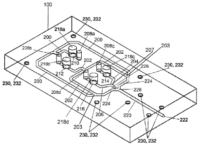
1 [0075] PRINT HEAD
2 [0076] Figure 3 shows a schematic perspective view of one
embodiment of a microfluidic
3 print head [100] for use in the system provided.
4 [0077] Referring to Figure 3, the illustrated embodiment depicts a
microfluidic print head
[100] comprising microfluidic channels for carrying various fluids. In the
illustrated embodiment,
6 the microfluidic channels have a cylindrical shape. However, channel
shapes other than
7 cylindrical could also be used in the print head provided herein. Channel
[200] is a conduit for a
8 cross-linking agent, channel [202] is a conduit for water. In the
illustrated embodiment, the
9 cross-linking agent and water, separately or together serve as the
"sheath fluid". Channel [204]
is a conduit for a first hydrogel composition (referred to as "hydrogel A"),
and channel [206] is a
11 conduit for a second hydrogel composition (referred to as "hydrogel B").
In a preferred
12 embodiment, one or more living cell types are compatible with and
optionally dispersed within
13 hydrogels A and/or B. In the illustrated embodiment, each microfluidic
channel comprises a
14 fluid inlet [208a, 208b, 208c, 208d], which allows fluid contained in
the connecting tubes [122] to
pass into the respective channels of the print head [100]. Downstream of the
fluid inlets [208a,
16 208b, 208c, 208d] are valves [210, 212, 214, 216] corresponding to each
channel. In the
17 illustrated embodiment, the valves serve as "fluidic switches", which
can be actuated to allow
18 and disallow flow of fluid through a channel, each valve having a
corresponding inlet [218, 218a,
19 218b, 218c, 218d], which facilitates actuation and de-actuation of the
valve. In one
embodiment, the valves [210, 212, 214, 216] can be electronically actuated. In
another
21 embodiment, the valves [210, 212, 214, 216] can be actuated by a change
in applied pressure,
22 for example, by way of solenoid pistons. Electronic or pressure
actuation of different valves
23 facilitates rapid change of the material dispensed, thereby allowing the
materials dispensed to
24 be composed of a controlled sequence of different materials.
[0078] Referring further to Figure 3, in the illustrated embodiment, the
crosslinking agent
26 channels [200] and water channels [202] intersect at intersection points
[203], such as in a "y-
27 shaped" configuration, joining together to form channels referred to
herein as "sheath flow
28 channels" [224] immediately downstream of the crosslinking agent and
water channels [200,
29 202]. The hydrogel A and hydrogel B channels [204, 206] intersect at an
intersection point
[207], such as in a "y-shaped" configuration, joining together to form a
channel referred to
31 herein as a "focussing channel" [226] immediately downstream of the two
hydrogel channels.
13
22828670.2
CA 02915737 2015-12-11
CA Application
Blakes Ref: 11143/00005
1 The sheath flow channels [224] and the focussing channel [226] intersect
at an intersection
2 point [228] in a three-pronged configuration, for the described
embodiment, wherein the
3 focussing channel [226] is flanked by the sheath flow channels [224],
joining together to form a
4 channel referred to herein as a dispensing channel [220]. The dispensing
channel [220]
terminates in the dispensing orifice [222]. In a preferred embodiment
illustrated in Figure 1, the
6 dispensing channel projects from the print head [100] terminating in the
dispensing orifice [114].
7 [0079] Referring further to Figure 3, in the illustrated
embodiment, the sheath flow channels
8 [224] and the dispensing channel [220] have larger diameters than the
focussing channel [226].
9 When hydraulic pressure is applied to the sheath flow [224] and focussing
channels [226], liquid
in the focussing channel [226] is compressed laterally and "focussed" into a
narrow stream
11 along the central axis of the focussing channel [226]. Upon intersection
with the focussing
12 channel [226] at the intersection point [228], fluid from the larger
diameter sheath flow channels
13 [224] surrounds and envelopes the narrower focussed stream of hydrogel
dispensed from the
14 focussing channel [226].
[0080] In a preferred embodiment, liquid in the sheath flow channels [224]
comprises a
16 chemical cross-linking agent and liquid in the focussing channel [226]
comprises one or more
17 chemically cross-linkable hydrogels comprising one or more living cell
types. When the one or
18 more chemically cross-linkable hydrogels are focussed into a narrow
stream in the focussing
19 channel [226] and then enveloped by the cross-linking agent in the
dispensing channel [220], at
least the exterior surface of the one or more chemically cross-linkable
hydrogels is solidified in
21 the dispensing channel [220], thereby creating a cross-linked or "solid"
hydrogel fiber. The
22 hydrogel fiber is then dispensed from the dispensing orifice [222] onto
the receiving surface in a
23 controlled manner, building a 3D structure, layer by layer.
24 [0081] In a particularly preferred embodiment, the sheath fluid
surrounding the hydrogel
fiber may also act to lubricate passage of the hydrogel fiber through the
dispensing channel
26 [220] until it is dispensed from the print head orifice [222].
27 [0082] In an embodiment, the sheath fluid comprises a chemical
cross-linking agent, water
28 or a combination thereof. In embodiments where the sheath fluid lacks a
chemical cross-linking
29 agent the hydrogel will not be solidified and would be dispensed as a
liquid. In order to adjust
the composition of the sheath fluid and start and/or stop solidification of
the hydrogel, a
31 crosslinking agent channel valve [210] and water channel valve [212] may
be actuated. It is
14
22828670.2
CA 02915737 2015-12-11
CA Application
Blakes Ref: 11143/00005
1 contemplated that dispensing a liquid rather than a solid hydrogel, or
dispensing sheath fluid
2 alone, may be desirable in order to construct some aspects of various
three dimensional
3 objects.
4 [0083] In an embodiment, the print head [100] may be configured to
receive and dispense
only one hydrogel material. In one embodiment, the print head may be
configured to receive
6 and dispense two or more hydrogel materials. For example, in an
embodiment where the print
7 head [100] is configured to receive two hydrogel materials, each, for
example, comprising a
8 different cell type, the system provided herein can be programed to
dispense a heterogeneous
9 cellular structure, wherein first and second cell types can be laid down
in controlled patterns
within and among layers, alone and/or in combination with one another.
Boundaries between
11 the two materials are controlled, e.g., by software, and the
programmable control processor is
12 used to instruct fluidic switched (e.g., one or more of valves [210],
[212], [214], [216]) to change
13 the flow of material within one or more microfluidic channels, thereby
changing the content of
14 the material being dispensed from the print head orifice. The number of
hydrogel materials that
can be received by and dispensed from the print head provided herein is
limited only by the size
16 of the print head that the user deems practical.
17 [0084] Referring to Figure 4, in one embodiment, the fluidic
switch is a valve comprising a
18 membrane [332] disposed over a bowl-shaped feature [318] formed in a
microfluidic channel
19 [308]. Upon application of pneumatic pressure (represented by arrows in
Figure 4) to the
exposed surface of the valve membrane [332], the valve membrane [332] will be
deflected into
21 the bowl shaped feature [318], thereby blocking passage of fluid through
microfluidic channel
22 [308]. In one preferred embodiment, the thickness of the valve membrane
[332] is about 150
23 pm. In embodiments where the valve membrane thickness is increased, a
skilled person would
24 understand that the applied pneumatic valve actuation pressure must be
increased accordingly.
Similarly, a valve membrane formed of less resilient material will require a
higher actuation
26 pressure. A skilled person would understand how to adjust the actuation
pressure to suit the
27 specific material of the valve membrane.
28 [0085] In one embodiment, the print head comprises alternative
fluidic switches for
29 regulating materials to be dispensed from the print head orifice. For
example, rather than using
valves, a mechanism for engaging or disengaging the pressure applied to each
channel could
31 be used to regulate material flow in the microfluidic channels.
22828670.2
CA 02915737 2015-12-11
CA Application
Blakes Ref: 11143/00005
1 [0086] In one embodiment, the print head further comprises an
extension tip comprising an
2 orifice for dispensing materials from the print head. Such an extension
tip facilitates precision
3 dispensing of materials and deposition thereof in confined areas such as,
for example, a well in
4 a multi-well plate (e.g., a standard microtitre plate, microwell plate or
microplate having 6, 24, 96
etc. wells) or a petri dish. Referring to the embodiment illustrated in Figure
5, a portion [500] of
6 the dispensing channel [220] nearest to the dispensing orifice [222] has
a larger diameter than
7 the upstream portion of the dispensing channel [220]. The extension tip
[502] comprises a tube
8 (e.g., made of plastic, glass or metal) having an exterior configured to
fit into the large-diameter
9 portion [500] of the dispensing channel and an inner surface (defining a
hollow space in the
tube) configured to align with the dispensing channel [220]. The extension tip
[502] can be
11 inserted into the large-diameter portion [500] of the dispensing
channel, thereby, extending the
12 length of the dispensing channel [220], which facilitates deposition of
material dispensed from
13 an orifice [503] in the extension tip [502] into confined spaces, such
as a well plate insert [504]
14 or petri dish (not shown).
[0087] Referring to the embodiment illustrated in Figure 1, the extension
tip [130] is a
16 projection extending from the print head [100], the extension tip [130]
terminating in the print
17 head orifice [114]. In this embodiment, the extension tip [130] is
integral with the print head.
18 [0088] In one embodiment, two or more hydrogel materials can be
arranged coaxially in a
19 hydrogel fiber dispensed from the system provided herein. Referring to
Figure 6, in the
illustrated embodiment, the print head [100] comprises microfluidic channels
arranged to
21 produce a coaxial hydrogel fiber comprising a hydrogel core material and
hydrogel shell
22 material. In the illustrated embodiment, the shell material, carried in
channels [508], is a rapidly
23 gelling hydrogel, such as alginate, and the core material, carried in
channel [506], is a different
24 hydrogel chosen by the user (e.g. collagen or fibrinogen). Channels
[508] and channel [506]
intersect at a hydrogel focussing intersection point [510], for example in a
"y-shaped"
26 configuration (similar to intersection [528] shown in Figure 3) joining
together to form a
27 focussing channel [226] downstream of channels [506] and [508]. At the
hydrogel focussing
28 intersection [510], the shell material focusses the core material
coaxially such that the shell
29 material forms a sheath around the core material. In preferred
embodiments, channels [508]
and [226] have a larger diameter than channel [506] to facilitate coaxial
focussing of the core
31 and shell materials. In a preferred embodiment, the purpose of the shell
material is to provide
32 the core material with physical structural support so that it may be
formed into a 3D geometry.
16
22828670.2
CA 02915737 2015-12-11
CA Application
Blakes Ref: 11143/00005
1 The core may be solidified after the material is deposited, the precise
method of solidification
2 being specific to different core materials. For example, the core may
comprise a material that
3 solidifies very slowly. In another embodiment, the core and shell
materials comprise the same
4 materials. In yet another embodiment, the shell material comprises a
hydrogel that rapidly
solidifies and the core material comprises a material that will not gel,
thereby facilitating
6 generation of a hollow fiber.
7 [0089] In one embodiment, the print head [100] depicted in Figure
6 could further comprise
8 additional core material channels, each with a corresponding fluidic
switch, for example a valve,
9 for regulating flow of the material therein. The fluidic switch
facilitates rapid and frequent
adjustments to the composition of the core material in the fiber being
dispensed, for example, by
11 commands provided by the programmable control processor.
12 [0090] In one embodiment, several print heads could be arranged,
for example in parallel, to
13 allow simultaneous printing of multiple structures. This would increase
throughput production.
14 [0091] In some embodiments the print head is disposable. Use of
disposable print heads
can reduce the likelihood of contamination of materials used in different
print jobs.
16 [0092] The print head can be fabricated, for example, using known
microfluidics molding
17 techniques (e.g., casting, imprinting or injection molding) and one or
more moldable polymers,
18 for example, polydimethylsiloxane (PDMS). Alternatively, commercially
available 3D printing
19 technology could be used to fabricate the print head.
[0093] FLUIDIC REMOVAL FEATURE
21 [0094] In an aspect, the invention provides a system for additive
manufacturing of three-
22 dimensional structures that comprises a feature for removing excess
sheath fluid from the
23 receiving surface where a first layer of material dispensed from the
orifice of the print head is
24 deposited and optionally from a surface of dispensed hydrogel. During
printing, it is possible
that excess sheath fluid will collect or "pool" on the receiving surface or on
a surface of
26 dispensed hydrogel. Such pooling can interfere with deposition of
hydrogel dispensed from the
27 print head orifice onto the receiving surface and/or onto one or more
layers of dispensed
28 hydrogel. For example, pooled sheath fluid may cause a dispensed
hydrogel fiber to slip from
29 its intended position in the 3D structure being printed. Therefore, in
embodiments of the
system, removal of excess sheath fluid from the receiving surface and
optionally from a surface
17
22828670.2
CA 02915737 2015-12-11
CA Application
Blakes Ref: 11143/00005
1 of the dispensed hydrogel by way of a fluidic removal feature may improve
additive
2 manufacturing of three-dimensional structures.
3 [0095] Excess sheath fluid may be removed from the receiving
surface or from a surface of
4 one or more layers of dispensed hydrogel by drawing the fluid off of
those surfaces, by allowing
or facilitating evaporation of the sheath fluid from those surfaces or, in
embodiments where the
6 receiving surface is porous, excess sheath fluid may be removed by
drawing it through the
7 porous surface.
8 [0096] In a preferred embodiment, the receiving surface comprises
a porous material, the
9 pores being sized to facilitate passage of sheath fluid there through and
sized to support one or
more layers of hydrogel deposited thereon.
11 [0097] Referring to figures 7 and 8, in the illustrated
embodiments, a print bed [108]
12 comprises a porous membrane [400], which serves as the surface for
receiving a first layer of
13 dispensed material (i.e., the receiving surface). The porous membrane
[400] is held in place in
14 the print bed [108] between a box piece [408] and a lid piece [402]. The
box piece [408] is a
container, which can be any shape suitable for receiving and containing liquid
(e.g., square,
16 round). The space inside of the box piece [408] is referred to as a
chamber [404]. The box
17 piece [408] has an upper surface [409] comprising a recessed lip [412]
extending the perimeter
18 of the upper surface [409] of the box piece [408]. The upper surface
[409] comprises an
19 aperture defined by one or more walls [410], the aperture being
surrounded by the recessed lip
[412] and extending into the box piece [408].
21 [0098] Referring further to the embodiments illustrated in figures
7 and 8, the lid piece [402]
22 comprises an upper surface [403] having an aperture [416] that extends
therethrough and
23 sidewalls [418] configured to fit around the recessed lip [412] of the
box piece [408], thereby
24 facilitating placement of the lid piece [402] on the upper surface [409]
of the box piece [408].
When the lid piece [402] is placed on the box piece [408] apertures in the box
and the lid piece
26 [416] align. In operation, the porous membrane [400] is placed on the
upper surface [409] of the
27 box piece [408] such that it extends over the aperture in the upper
surface [409] of the box piece
28 [408], the lid piece [402] is then placed on top of the box piece [408]
and pressed downward.
29 The downward pressure of the lid piece [402] stretches the porous
membrane [400] over the
aperture in the upper surface [409] of the box piece [408], thereby retaining
the porous
31 membrane [400] between the box piece [408] and the lid piece [402]. In
preferred embodiments,
18
22828670.2
CA 02915737 2015-12-11
CA Application
Blakes Ref: 11143/00005
1 the lid piece [402] and box piece [408] fit together snuggly, thereby
providing a connection that
2 will remain secure during operation of the system provided herein.
3 [0099] Referring further to the embodiments illustrated in figures
7 and 8, the box piece
4 [408] comprises a solid base [414] and at least one outlet duct [406] for
directing fluid away from
the chamber [404], and a vacuum source (not shown) in fluid communication with
the outlet duct
6 [406] of the chamber [404]. The porous membrane [400] comprises pores
sized to facilitate
7 passage of sheath fluid. The vacuum source (not shown) coupled to the
outlet duct [406] may
8 be actuated to draw the excess sheath fluid collected on the porous
membrane [400] through
9 the porous membrane [400] into the chamber [404] and from the chamber
[404] through the
outlet [406], leaving the hydrogel fiber in its dispensed configuration on top
of the porous
11 membrane [400].
12 [00100] In a preferred embodiment, a feature for removing excess sheath
fluid from the
13 receiving surface and optionally from a surface of dispensed hydrogel
can be included in a
14 system configured to dispense materials into a multiwall plate or petri
dish. For example,
referring to Figure 9, in the illustrated embodiment, a commercially available
well-plate insert
16 [504], is placed on top of the box piece [408]. Some well-plate inserts
[504] have a basket
17 shape with a base made out of a porous membrane material [512]. In the
illustrated
18 embodiment, a gasket [514] is placed between the well-plate insert [512]
and the box piece
19 [408] to improve sealing between the two pieces [504 and 408]. In such
embodiments, the
porous membrane [512] of the well-plate inset [504] would serve as the
"receiving surface" and
21 any excess sheath fluid could be removed therefrom using a vacuum
coupled to the outlet duct
22 [406], as described above, or using one of the other fluidic removal
features described below.
23 [00101] In one embodiment (not shown), the receiving surface on the
print bed comprises or
24 is placed adjacent to an absorptive material, which facilitates
absorption of excess sheath fluid
from the receiving surface. For example, a well-plate insert having a base
made out of a porous
26 membrane material (for example, as shown in Figure 9), or any other
porous membrane
27 substrate, could be placed on top of or adjacent to an absorptive
material, such as, for example,
28 a sponge. The absorptive material would act to draw away from the
receiving surface excess
29 sheath fluid. In embodiments where the absorbent material is disposed
below a porous
receiving surface, excess sheath fluid on the receiving surface would be drawn
through the
31 porous receiving surface and into the absorptive material, thereby
preventing pooling of excess
19
22828670.2
CA 02915737 2015-12-11
CA Application
Blakes Ref: 11143/00005
1 sheath fluid on the receiving surface. In embodiments where the absorbent
material is disposed
2 immediately beside or on top of a portion of the receiving surface (e.g.,
on the periphery of the
3 receiving surface so as not to interfere with deposition of dispensed
material) excess sheath
4 fluid would be drawn off of the receiving surface and into the absorbent
material.
[00102] In one embodiment (not shown), rather than using one of the print beds
described
6 above, one or more tubes may be provided in an area near the receiving
surface and near the
7 print head orifice. The one or more tubes may be fluidly coupled to a
vacuum source (not
8 shown), which can provide suction for removing excess sheath fluid from
the receiving surface
9 and optionally from a surface of dispensed hydrogel. In such embodiments,
a solid or porous
receiving surface may also be used.
11 [00103] In one embodiment, illustrated in Figure 10, the print
head is configured to further
12 comprise one or more vacuum channels [700a, 700b], the one or more
vacuum channels each
13 having an orifice [702a, 702b] situated near the print head orifice
[222]. The one or more
14 vacuum channels [700a, 700b] each have an inlet [704a, 704b] configured
to facilitate fluid
communication with one or more vacuums (not shown). When the print head [100]
is in fluid
16 communication with a vacuum, the one or more vacuum channels [702a,
702b] direct negative
17 pressure to an area of the receiving surface where materials are being
dispensed or have been
18 dispensed from the print head orifice [222] and/or to a portion of the
surface area of the
19 dispensed hydrogel, thereby drawing up excess sheath fluid from the
receiving surface and
optionally from a surface of the dispensed hydrogel, thereby eliminating
pooling of sheath fluid
21 on the receiving surface and/or the dispensed hydrogel.
22 [00104] In one embodiment, the one or more vacuum tubes are provided, at
least in part, in
23 one or more extensions projecting from the print head, the extensions
projecting in the same
24 general direction as the extension comprising the print head orifice and
dispensing channel
(see, for example, Figure 10). In such embodiments, the one or more extensions
comprising
26 vacuum tubes do not extend further than the extension comprising the
print head orifice and
27 dispensing channel so as not to interfere with dispensed and deposited
hydrogel.
28 [00105] It is contemplated that in some embodiments, the fluid removal
feature may be a
29 feature of the sheath fluid composition itself. For example, the sheath
fluid composition may be
designed to evaporate after it is dispensed from the print head orifice,
thereby eliminating
31 pooling of excess sheath fluid on the receiving surface or on surfaces
of dispensed hydrogel.
22828670.2
CA 02915737 2015-12-11
CA Application
Blokes Ref: 11143/00005
1 For example, the sheath fluid may have a boiling point that results in
evaporation after being
2 dispensed, while remaining in a liquid state prior to being dispensed.
3 [00106] METHOD OF PRINTING A THREE DIMENSIONAL STRUCTURE
4 [00107] In an aspect, a method of printing a three-dimensional
(3D) structure is provided.
[00108] The method first comprises providing a design for a 3D structure to be
printed. The
6 design may be created using commercially available CAD software. In one
embodiment, the
7 design comprises information regarding specific materials (e.g., for
heterogeneous structures
8 comprising multiple materials) to be assigned to specific geometrical
locations in the design.
9 [00109] The method comprises the use of a 3D printer, the printer
comprising: a print head, a
receiving surface for receiving material dispensed by the print head; and a
positioning unit
11 operably coupled to the receiving surface, the positioning unit for
positioning the print head at a
12 location in three dimensional space above the receiving surface. For
example, various
13 embodiments of the printing system provided herein may be used in the
method of printing a 3D
14 structure.
[00110] The method comprises providing at least two materials to be dispensed
by the print
16 head, such as a sheath fluid and a hydrogel fluid. In preferred
embodiments, one or more cell
17 types are compatible with, and optionally dispensed within, the
hydrogel. In a preferred
18 embodiment, the sheath fluid serves as a lubricating agent for
lubricating movement of the
19 hydrogel within and from the print head. In a preferred embodiment, the
sheath fluid comprises
a cross-linking agent for solidifying at least a portion of the hydrogel
before or while it is
21 dispensed from the print head.
22 [00111] The method comprises communicating the design to the 3D printer.
Communication
23 can be achieved, for example, by a programmable control processor.
24 [00112] The method comprises controlling relative positioning of
the print head and the
receiving surface in three dimensional space and simultaneously dispensing
from the print head
26 the sheath fluid and the hydrogel, alone or in combination. In preferred
embodiments, the
27 materials dispensed from the print ahead are dispensed coaxially, such
that the sheath fluid
28 envelopes the hydrogel. Such coaxial arrangement allows the cross-
linking agent to solidify the
29 hydrogel, thereby resulting in a solid hydrogel fiber, which is
dispensed from the printer head.
21
22828670.2
CA 02915737 2015-12-11
CA Application
Blakes Ref: 11143/00005
1 [00113] The method comprises depositing a first layer of the dispensed
materials on the
2 receiving surface, the first layer comprising an arrangement of the
material specified by the
3 design and iteratively repeating the depositing step, depositing
subsequent material onto the
4 first and subsequent layers of material, thereby depositing layer upon
layer of dispensed
materials in a geometric arrangement specified by the design to produce the
cell-laden 3D
6 structure.
7 [00114] In preferred embodiments, a plurality of materials, for
example multiple hydrogels, at
8 least some of which comprise one or more cell types, are deposited in a
controlled sequence,
9 thereby allowing a controlled arrangement of hydrogels and cell types to
be deposited in a
geometric arrangement specified by the design.
11 [00115] In preferred embodiments, the method comprises removing excess
sheath fluid from
12 the receiving surface and optionally from the surface of the dispensed
hydrogel. For example,
13 the step of removing the excess sheath fluid can be done continuously
throughout the printing
14 process, thereby removing excess fluid that may otherwise interfere with
layering the dispensed
materials in the geometric arrangement provided by the design. Alternatively,
the step of
16 removing excess sheath fluid may be done intermittently throughout the
printing process in
17 sequence with or simultaneously with one or more depositing steps. In
some embodiments,
18 removal of excess sheath fluid is achieved by drawing the fluid off of
the receiving surface and
19 optionally off of a surface of the dispensed hydrogel. In another
embodiment removal of excess
sheath fluid is achieved by drawing excess fluid through the receiving
surface, the receiving
21 surface comprising pores sized to allow passage of the sheath fluid. In
another embodiment
22 removal of excess sheath fluid is achieved by providing a sheath fluid
that evaporates after
23 being dispensed from the print head orifice.
24 [00116] EXEMPLARY USES OF EMBODIMENTS OF THE SYSTEM AND METHOD OF
PRINTING CELL-LADEN THREE DIMENSIONAL STRUCTURES
26 [00117] In some embodiments, structures generated using the system and
method provided
27 herein can be useful in the field of drug discovery, where, for example,
determining cellular
28 responses to various chemical compounds and compositions are of
interest. Use of 3D cell
29 cultures fabricated using embodiments of the systems and methods
provided herein may
provide experimental conditions that more closely resemble in vivo cellular
and tissue conditions
31 relative to 2D cell cultures. 3D arrangement of the cells may more
closely mimic in vivo cell-cell
22
22828670.2
CA 02915737 2015-12-11
CA Application
Blakes Ref: 11143/00005
1 interactions and responses to external stimuli and the heterogeneous
nature of the 3D
2 structures that can be generated using the apparatus and methods provided
permit study of
3 tissues and potentially organs. It is contemplated that 3D cell-laden
structures fabricated using
4 embodiments of the systems and methods provided herein may provide a
similar benefit to the
cosmetics industry by offering an alternative means to testing cosmetic
products.
6 [00118] In some embodiments, various embodiments of the system and method
provided
7 herein are compatible with standard well-plate technology. Well-plates or
well-plate inserts may
8 be used with or as part of the print bed in the methods and systems
provided herein. Various
9 embodiments of the system and method provided herein are thus compatible
with instruments
and practices that utilize well-plates, allowing them to be readily integrated
into existing process
11 streams.
12 [00119] In some embodiments, the microfluidic channels within the
print head are compatible
13 with other microfluidic modules. For example, known microfluidic modules
may be included in
14 the print head of the systems provided herein upstream of the print head
orifice. Such modules
may include, for example, cell counting, cell sorting, cell analyzing, and/or
concentration
16 gradient generating modules.
17 [00120] In some embodiments, throughput of 3D printing may be increased
by adding to the
18 system additional print heads in parallel. Each print head comprising
all of the elements required
19 to print a multi-material structure, thus allowing several 3D structures
to be printed
simultaneously by including additional print heads in the system.
21 [00121] Although the invention has been described with reference to
certain specific
22 embodiments, various modifications thereof will be apparent to those
skilled in the art without
23 departing from the purpose and scope of the invention as outlined in the
claims appended
24 hereto. Any examples provided herein are included solely for the purpose
of illustrating the
invention and are not intended to limit the invention in any way. Any drawings
provided herein
26 are solely for the purpose of illustrating various aspects of the
invention and are not intended to
27 be drawn to scale or to limit the invention in any way.
23
22828670.2
CA 02915737 2015-12-11
CA Application
Blokes Ref: 11143/00005
1 [00122] REFERENCES
2 [00123] The following references are provided as examples of the known
art relating to the
3 present invention. The following listing is not intended to comprise a
comprehensive list of all
4 relevant art.
1. Su-Jung Shin, Ji-Young Park, Jin-Young Lee, Ho Park, Yong-Doo Park, Kyu-
Back Lee,
6 Chang-Mo Whang, and Sang-Hoon Lee, "On the fly" continuous generation of
alginate
7 fibers using a microfluidic device", Langmuir, Vol. 23, 2007, pp. 9104-
9108.
8 2. Saif Khalil, and Wei Sun, "Bioprinting endothelial cells with
alginate for 3D tissue
9 constructs", Journal of Biomechanical Engineering, Vol. 131, 2009, pp.
111002-1 -
111002-8.
11 3. Min Hu, Rensheng Deng, Karl M. Schumacher, Motoichi Kurisawa,
Hongye Ye, Kristy
12 Purnamawati, and Jackie Y. Ying, "Hydrodynamic spinning of hydrogel
fibers",
13 Biomaterials, Vol. 31, 2010, pp. 863-869.
14 4. Byung Kim, Intae Kim, Wooseok Choi, Sun Won Kim, JooSung Kim, and
Geunbae Lim,
"Fabrication of cell-encapsulated alginate microfiber scaffold using
microfluidic channel",
16 Journal of Manufacturing Science and Engineering, Vol. 130, 2008, pp.
021 01 6-1 -
17 021016-6.
18 5. Edward Kang, Su-Jung Shin, Kwang Ho Lee, and Sang-Hoon Lee, "Novel
PDMS
19 cylindrical channels that generate coaxial flow, and application to
fabrication of
microfibers and particles", Lab on a Chip, Vol. 10, 2010, pp. 1856-1861.
21 6. Hiroaki Onoe, Riho Gojo, Yukiko Tsuda, Daisuke Kiriyaand, and
Shoji Takeuchi, "Core-
22 shell gel wires for the construction of large area heterogeneous
structures with
23 biomaterials", IEEE MEMS Conference, 2010, pp. 248-251.
24 7. Setareh Ghorbanian (2010), Microfluidic probe for direct write of
soft cell scaffolds,
M.Eng. Thesis. McGill University: Canada.
26 8. Edward Kang, Gi Seok Jeong, Yoon Young Choi, Kwang Ho Lee, Ali
Khademhosseini,
27 and Sang- Hoon Lee, "Digitally tunable physicochemical coding of
material composition
28 and topography in continuous microfibers", Nature Materials, Vol. 10,
2011, pp. 877-883.
24
22828670.2
CA 02915737 2015-12-11
CA Application
Blakes Ref: 11143/00005
1 9. EP 2489779 Al
2 10. US 2006/0105011 Al
3 11. US 2011/0136162 Al
4 12. US 2012/0089238 Al
13. WO 2012009363 Al
6
7
22828670.2