Note: Descriptions are shown in the official language in which they were submitted.
CA 02289015 1999-10-28
WO 98/49753 PCT/EP98/01960
Connector System
TECHNICAL FIELD
s This invention relates to a connector system for coupling signal
transmission conductor means via mating means controlled by a self
latching mechanism.
BACKGROUND ART
Connector systems of this type are known and universally used in various
areas demanding very good qualities of precision and reliability.
General configurations of these systems comprise two tubular bodies
1 s forming a plug and socket arrangement, each of these plug and socket
bodies being intended to be coupled to conductors for the transmission of
electric, photonic or fluid signals, and the plug and socket bodies being for
engagement into one another. Upon insertion of the plug body into the
socket body a self latching mechanism automatically locks the plug body
2o in the socket body by mere pushing the plug body axially into the socket
body. When required, the plug body is disengaged from the socket body
by a straight axial pull on an outer release sleeve which initially allows
unlocking of the self latching mechanism and then withdrawal of the plug
body out of the socket body. Accordingly, the connection between plug
2 ~ body and socket body cannot be broken by pulling on the cable
containing the signal transmission conductors or any other component
part of the plug and socket bodies other than the outer release sleeve.
In a well known of these connector systems, a plurality of peripheral
3 o elastic tongues are mounted on the plug body and each of said tongues
bears on outwardly projecting latch whereby each said latches may
CA 02289015 1999-10-28
WO 98/49753 PCT/EP98/01960
2
resiliently move radially on the plug body. An outer sleeve slidably
mounted on the plug body for axial movement therealong comprises an
extension surrounding the peripheral elastic tongues and this extension
has a plurality of transverse windows respectively placed over the
s projecting latches, whereby axial movement of the sleeve over the plug
body causes the windows of the sleeve extension to act as ramps forcing
the projecting latches radially and inwardly with respect to the plug body.
The socket body comprises an inner circular groove for catching the
projecting latches upon insertion of the plug body into the socket body.
so According to the general operation described hereabove, connection of
the system is obtained by mere insertion of the plug body into the socket
body, whereby the projecting latches radially contract to enter into the
socket body and then expand into the catching groove thereof, thus
locking the assembly of plug body and socket body. Disconnection of the
is system is obtained by axial pull on the outer sleeve the windows of which
radially contract the projecting latches thereby allowing extraction thereof
from the catching groove whereby the plug body may be withdrawn from
the socket body.
2u Another of these connector systems, described in US-3160457,
comprises a plurality of peripheral elastic tongues with protruding latches
mounted on a release sleeve slidably arranged over the plug body which
carries a truncated cone ramp disposed under the latches. A release
space is provided between the latches and the plug body. The socket
2~ body comprises an inner circular groove for catching the protruding
latches upon insertion of the plug body into the socket body. Connection
of the system is obtained by pushing the plug body into the socket body
whereby the latches may contract in the release space and enter into the
socket body and then expand into the catching groove. In that
~ o configuration, any pul! on the plug body other than on the release sleeve
results in the truncated cone ramp of the plug body further urging the
CA 02289015 1999-10-28
WO 98/49753 PCT/EP98/01960
3
latches in the catching groove of the socket body. Disconnection of the
self-latching assembly is obtained by pulling the release sleeve whereby
the latches may contract in the release space to allow withdrawal of the
plug body from the socket body.
Still a further of these connector systems is described in FR-A-2159701. A
plug body comprises a plurality of peripheral elastic tongues with inwardly
projecting latches intended to engage an annular catching groove
peripherally arranged on a socket body. A release sleeve is mounted for
to movement over the plug body and comprises at one end a bevelled
portion orientated towards the inwardly projecting latches and capable of
passing beneath them, and at the other end, a stop arrangement
cooperating with a circlip mounted elastically on the plug member. The
internal surface of the release sleeve is staged so as to block the inwardly
1s projecting latches in the catching groove of the socket body when the stop
arrangement is engaged on the circlip and to allow the latches to expand
radially out of the catching groove when the stop arrangement is released
from the circlip, which allows the bevelled portion of the release sleeve to
pass beneath the latches to spread them radially apart arid unlock the
2u self-latching connection.
All these connector systems are definitely fail-proof with operators who
know or can recognise that they have in hands a plug body or a socket
body that are made to fit to one another whereby the connection can be
2s secured either by inserting the plug body into the socket body or by
engaging the socket body over the plug body. However, this is not
necessarily the case in high stress or so-called blind conditions such as
exist, for example, in military operation. A fait-proof connection cannot be
assured if the operator may be puzzled by having in hand the plug body
or the socket body. And that situation may be particularly acute where
connection has to be made on loose cables.
CA 02289015 1999-10-28
4
DE-A-2063258 describes a two halves connector system in which each
half comprises an inner tubular body having its rear end connected to a
pipe via a clamp. The front end of the body is provided with an external
circular groove arranged in an enlarged end portion the rear end of which
s forms an abutment. Forwardly axially projecting resilient arms are formed
circumferentially at the fore edge of the circular groove and at a same
distance from one another. Resilient arms terminate into enlargements with
inwardly oriented projections which have substantially the same shape as
the transverse section of the groove, and the width of these arms and
to projections is such that by mating two identical connector halves the arms
of the two halves interpenetrate. On the outer side of the tubular body is
slidably mounted a control sleeve which is held against the abutment by a
spring. This control sleeve has an enlarged forwardly projecting portion the
axial length of which is equal to the axial length of the enlarged end portion
is of the body and the inner diameter of which is equal to the diameter of a
circle surrounding the external edges of the projection of the resilient arms.
Control sleeve is externally grooved for manual operation. Connection of
the two halves of the system is obtained by mating the two halves with their
respective arms interpenetrating, whereby the arms radially expand on the
2o front ends of the tubular bodies and simultaneously push the fore edges of
the control sleeves against the bias of the springs until their projections
can
fall into the corresponding circular groove whereby the control sleeves may
be pushed forwardly by the springs and their enlarged forwardly projecting
portions may cover the ends of the enlargements of the resilient arms. The
25 system is thus locked and secured against draw on the respective pipes.
To unlock the system, it is necessary to draw the grooved portions of the
two control sleeves in opposite directions whereby the resilient arms of
both connector halves may have their projections expanded to be extracted
from the corresponding grooves. In a variant aimed at avoiding holding the
3o connector halves by the respective clamped pipes for connection
purposes, the rear portion of the control sleeve is partly covered by a
sleeve fixed to the inner body. In a further variant, the control sleeve is
AMENO~D SHEET
CA 02289015 1999-10-28
4a
completely covered by the sleeve fixed to the body and comprises radial
studs projecting through longitudinal slots of the covering sleeve.
DISCLOSURE OF THE INVENTION
It is an object of this invention to avoid that failure potential by means of
a
connector system which avoids any puzzling condition for the operator,
even under the worse environmental conditions. A further object of the
invention is to achieve a connector system that simplifies logistics in the
to coupling of signal transmission conductor means. And a still further object
of the invention is to propose a connector system that is versatile and easy
to manufacture.
To this effect, the connector system according to the invention complies
with the definitions given in the claims.
Accordingly, a connector unit comprising resiliently movable latch means
circumferentially alternating with latch catching means allows mating of a
first connector unit with a second identical connector unit by mere
2 o insertion and self-latching of the resiliently movable latch means of the
first connector unit into the latch catching means of the second connector
unit while the latch catching means of the first connector unit
simultaneously house and catch the resiliently movable latch means of the
second connector unit. There are no hazardous or search manipulations
of different elements and no questions about what has to be done with
elements which differ visually, tactily or operatively. A simple fail-proof
one
motion insertion is only required to achieve the coupling of the signal
transmission conductor means. As the connector unit acts both as a plug
body and a socket body, logistics are simplified either for the types of
3o elements that have to be stored or in the preparation of cable assemblies.
Tutoring of operators is drastically reduced, whatever their educational
background. And manufacture of the connector system is also simplified
AP~E~D~D ~++EtT
I I~ '~ I I i1
CA 02289015 2002-08-08
i w
75490-35
4b
by the reduction of the number of different elements.
In summary, the invention provides a connector
system for coupling signal transmission conductor means via
mating means controlled by a self-latching mechanism, in
which a connector unit comprises a central tubular body
secured to a latching shell having a plurality of resilient
tongues circumferentially arranged at a same distance from
one another each said tongues having a projecting latch, a
catching sleeve secured to said central tubular body having
latch catching means circumferentially alternating with
said latches, and a control sleeve mounted for longitudinal
movement on said connector unit, characterized by a sleeve
slidably mounted on said latching shell said sleeve having
at one end a plurality of peripheral extension arms
respectively extending along said tongues and each said
extension arms having ramp means for urging a corresponding
latch against the resiliency thereof, said catching sleeve
comprising a plurality of peripheral arms circumferentially
arranged at a same distance from one another and located
angularly between said tongues and extension arms said
peripheral arms having each a said latch catching means, and
said control sleeve being fastened to said slidable sleeve,
whereby self-latching and release of the connector unit with
a second identical connector unit is achieved by direct
push-pull action on the control sleeve.
CA 02289015 1999-10-28
WO 98/49753 PCT/EP98/01960
In a preferred embodiment, the connector unit comprises a plurality of
resiliently movable latch means circumferentially arranged at a distance
from one another and a plurality of latch catching means circumferentially
alternating with said latch means, whereby a still further ease of coupling
is achieved. And the latch means may be movable radially or
circumferentially.
Where ramp means are provided for urging the latch means against the
1o resiliency thereof, unmating becomes effortless as the latching means are
released from the latch catching means.
Where a control sleeve is mounted for longitudinal movement on the
connector unit, with the ramp means connected to the control sleeve, self
15 latching and release of the connection may be achieved by direct push-
pull action on the control sleeve. A control sleeve may also be mounted for
longitudinal movement on the connector unit, with the latch means
connected to the control sleeve.
2o Wall means may be provided for urging the latch means in latching
condition to strengthen the locking condition of the latch means in the
latch catching means.
And spring biased muff means may be mounted in the connector unit to
25 reciprocate over the latch means and latch catching means for tightness
purposes andlor to prevent unwanted contact with the signal transmission
conductor means in the connector unit andlor to protect the latch means
and latch catching means from environmental aggression.
3o BRIEF DESCRIPTION OF DRAWINGS
CA 02289015 1999-10-28
6
These and other objects, features and advantages of the invention will
become readily apparent from the following detailed description with
reference to the accompanying drawings which show, diagrammatically
and by way of example only, two preferred but still illustrative
embodiments of the invention.
Figure 1 is a longitudinal section of the connector unit of the first
embodiment of the invention.
Figure 2 is a view according to line I-I of Figure 1.
Figures 3 and 4, 5 and 6, 7 and 8, 9 and 10, are respectively side
elevations and top plan views of details of Figure 1.
Figure 11 is a longitudinal section showing the connector unit of the first
embodiment in mating condition with an identical connector unit.
Figure 12 is a longitudinal section of the second embodiment of the
invention.
Figure 13 is a longitudinal section showing the connector unit of the
second embodiment in mating condition with an identical connector unit.
MODES OF CARRYING OUT THE INVENTION
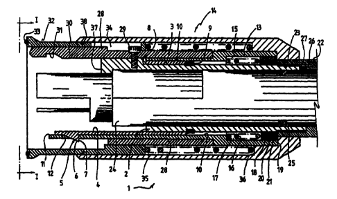
The connector unit 1 shown in Figures 1 and 2 comprises a central
tubular body 2 on which is mounted a latching shell 3 (Figs 1, 2, 5, 6)
having three peripheral resilient tongues 4 extending at 120° from one
3o another, each bearing at its end an outwardly projecting latch 5 having a
forward surface (6) inclined towards the end of the tongue 4 and a
rearward
i~~~~i~d~~:r ~-i~.~T,
CA 02289015 1999-10-28
WO 98/49753 PCT/EP98/01960
7
abutment surface 7 substantially perpendicular to the tongue 4. Latching
shell 3 is affixed to the central tubular body 2 between a shoulder 8
thereof and a ring 9 fastened thereto.
Over latching shell 3 is a slidable sleeve 10 (Figures 1, 2, 7, 8) having at
one end three peripheral extension arms 11 arranged at substantially
120° from one another over the tongues 4 of latching shell 3. Each arm
11
is provided with a transverse window 12 located over the corresponding
latch 5. The sleeve 10 abuts against shoulder 8 of central tubular body 2
1o and its rear end 13 is fastened , for example glued, to a control sleeve 14
surrounding the connector unit 1. Inside the rear end 13 of sleeve 10 is a
chamber 15 in which is located a coil spring 16 of which one end abuts
against a wall 17 of chamber 15 and the other end abuts against a ring 18
movable in chamber 15 and the rear end of which bears against an
1~ abutment wall 19 of the rear end of control sleeve 14. Two O-rings 20 and
21 on ring 18 assure tightness between ring 18, sleeve 10 and central
tubular body 2.
The rear end of control sleeve 14 slidingly bears on the end of a collet nut
20 22 meshing on a threaded end portion 23 of central tubular body 2 and
bearing against the rear end of ring 18. Collet nut 22 holds a signal
transmission conductor assembly 24 extending in central tubular body 2
and abuting against a shoulder 37 thereof. An O-ring 25 assures tightness
between signal transmission conductor assembly 24 and central tubular
2s body 2. Signal transmission conductor assembly 24 is secured angularly
to central tubular body 2 via a stud 26 positioned in a groove 27 of central
tubular body. Signal transmission conductor assembly 24 can be of any
kind for transmitting electric, photonic or fluid signals, and needs no
further description.
CA 02289015 1999-10-28
WO 98/49753 PCT/EP98/01960
8
Over the sleeve 10 and central tubular body 2 is mounted a catching
sleeve 28 (Figures 1, 2, 9,10) affxed to central tubular body 2 by a screw
29. Catching sleeve 28 comprises three peripheral arms 30 arranged at
substantially 120° from one another and located angularly between
s resilient tongues 4 of latching shell 3 and windowed arms 11 of sleeve 10,
and each peripheral arm 30 is provided with an inner latch catching
groove 31 having substantially the same shape as latches 5, however in
reversed condition. The latches 5 and windows 12 are thus
circumferentially alternating with the latch catching grooves 31.
The front end of control sleeve 7 4 extends somewhat back of the front end
of peripheral arms 30 of catching sleeve 28 and between catching sleeve
28 and control sleeve 14 is mounted a sliding muff 32 (Figure 1, 2, 3, 4)
the front end of which contains an O-ring 33. The rear end of muff 32 is
1 s slotted ai 34 for longitudinal positioning and angular guiding by screw
29,
and a spring 35 located between the rear end of muff 32 and an inner
abutment wall 36 of control sleeve 14 urges forwardly muff 32 over the
front end of the peripheral arms 30 of catching sleeve and the latches 5 of
latching shell 3. An O-ring 38 assures tightness between muff 32 and
2 a control sleeve 14.
Operation of this connector unit is as follows, reference being made to
Figure 11. Two identical connector units 7 are positioned in front of one
another and pushed against one another and the O-rings 33 of muffs 32
25 assure tightness at that location. The muffs 32 retract within the control
sleeves 14, against the bias of springs 35, whereby the peripheral arms
30 of the catching sleeve 28 of each of the connector units 1 may be
respectively inserted between the peripheral arms 30 of the catching
sleeve 28 of the other connector unit. The latches 5 and windows 12 of
30 latching shell 3 and sleeve 10 of each connector unit 1 may thus
respectively engage under the peripheral arms 30 of the catching sleeve
CA 02289015 1999-10-28
WO 98/49753 PCT/EP98/019b0
9
28 of the other connector unit 1. Due to the bias of resilient tongues 4, the
latches 5 engage the corresponding latch catching grooves 31 with their
rearward abutment 7 bearing against the corresponding reversed shape
of the latch catching groove 31. The assembly of the two connector units 1
s is thus secured and tight. Any pull on the collet nuts 22 or on the cables
(not shown) connected to the signal transmission conductor assemblies
24 is transmitted to the latches 5 and latch catching grooves 31 via central
tubular bodies 2, latching shells 3, resilient tongues 4, and screws 29, and
the assembly of the connector units 1 remains firmly secured.
Disassembly is achieved by mere pull on one or both the control sleeves
14 of the connector units 1 which retract against the bias of springs 16.
Retraction of control sleeve 14 against the bias of spring 16 draws sleeve
10 the extension arms 11 of which drive the windows 12 along inclined
1s surfaces 6 of latches 5 thereby urging latches 5 out of the latch catching
grooves 31. The connector units 1 may thus be separated from one
another while muffs 32 are pushed by springs 35 over the latches 5 and
peripheral arms 30 of catching sleeves 28 and the end of the signal
transmission conductor assemblies 24.
The second embodiment shown in Figure 12 comprises a connector unit
39 having a central tubular body 40 with three peripheral arms 41
extending at 120° from one another, each terminating in an upwardly
inclined wall 42. Over the central tubular body 40 is slidably mounted a
2s latching shell 43 having three peripheral resilient tongues 44 respectively
extending at 120° from one another at some distance over the arms 41.
Latching shell 43 is limited in its forward motion by a shoulder 50 of
central tubular body 40 and it is angularly fixed with respect to central
tubular body 40 via a stud and groove arrangement (not shown). Resilient
~o tongues 44 terminate each in an outwardly projecting latch 45 having a
rearward latching surface 46 and a front inwardly oriented surface 47
CA 02289015 1999-10-28
WO 98/49753 PCT/EP98/01960
bearing on inclined wall 42 of arm 41. Reanrvard portion 48 of latching
shell 43 includes a chamber 49 in which is located a coil spring 51 of
which one end abuts against the front wall of chamber 49 and the other
end abuts against a ring 52 movable in chamber 49 and over central
tubular body 40. The rear end of ring 52 bears against an abutment wall
53 of the rear end of a control sleeve 54 surrounding the connector unit 39
and affixed, for example glued, at 55 to latching shell 43. Two O-rings 56
on ring 52 provide tightness between ring 52, latching shell 43 and central
tubular body 40.
The rear end of control sleeve 54 slidingly bears on the end of a collet nut
57 meshing on a threaded end portion 58 of central tubular body 40 and
bearing against the rear end of ring 52. Collet nut 57 holds a signal
transmission conductor assembly 59 extending and secured longitudinally
and angularly in central tubular body 40 as that of the first embodiment.
An O-ring 60 provides tightness between signal transmission conductor
assembly 59 and central tubular body 40.
Over the latching shell 43 and the central tubular body 40 is mounted a
2o catching sleeve 61 affixed to central tubular body 40 via a screw 62.
Catching sleeve 61 comprises three peripheral arms 63 arranged at
substantially 120° from one another and located angularly between
resilient tongues 44 of latching shell 43 and peripheral arms 41 of central
tubular body 40. Each peripheral arm 63 of catching sleeve 61 is provided
2s with an inner latch catching groove 64 having substantially the same
shape as latches 45 however in reversed arrangement. The latches 45
and arms 41 are thus circumferentially alternating with the latch catching
grooves 64.
3o The front end of control sleeve 54 extends somewhat back of the front end
of peripheral arms 63 of catching sleeve 69 and between catching sleeve
CA 02289015 1999-10-28
WO 98/49753 PCT/EP98/01960
11
61 and control sleeve 54 is mounted a sliding muff 65 the front end of
which contains an O-ring 66. The rear end of muff 65 is slotted at 67 for
longitudinal and angular positioning by screw 62, and a spring 68
positioned between the rear end of muff 65 and an inner abutment wall 69
of control sleeve 54 urges forwardly muff 65 over the front end of
peripheral arms fi3 of catching sleeve 61 and the latches 45 and arms 41.
An O-ring 70 assures tightness between muff 65 and control sleeve 54.
Operation of this embodiment is as follows with reference to Figure 13.
so Two identical connector units 39 are positioned in front of one another and
pushed against one another, whereas the O-rings 66 assure tightness at
that level. The muffs 65 retract within control sleeves 54 against the bias
of springs 68, whereby the peripheral arms 63 of catching sleeve 61 of
each of the connector units 39 may be respectively inserted between the
peripheral arms 63 of the catching sleeve 61 of the other connector unit.
The latches 45 and arms 41 of each connector unit 39 may thus
respectively engage under the peripheral arms 63 of the other connector
unit 39. Due to the bias of resilient tongues 44, the latches 45 engage the
corresponding latch catching grooves 64 with their rearward latching
2u surface 46 bearing against the corresponding surface of the latch catching
groove 64. The assembly of the two connector units 39 is thus secured
and tight. Any pull on the collet nuts 57 or on the cables (not shown)
connected to the signal transmission conductor assemblies 59 is
transmitted to the central tubular bodies 40 the peripheral arms 41 and
2s inclined walls 42 of which urge the latches 45 into the latch catching
grooves 64, and the assembly of the connector units 39 remains strongly
secured. Disassembly is achieved by simple pull on one or both the
control sleeves 54 of the connector units 39. Retraction of the control
sleeve 54 against the bias of spring 51 draws latching shell 43 the latches
30 45 of which are urged out of the latch catching grooves 64 by the walls
thereof and along inclined walls 42 or peripheral arms 41. The connector
CA 02289015 1999-10-28
WO 98/49753 PCT/EP98/01960
12
units may thus be separated from one another while muffs 65 are pushed
by springs 68 over the latches 45 and peripheral arms 63 of catching
sleeves 61 as well as the end of signal transmission conductor
assemblies.
Variants are available.
For example, the number of latched tongues and latch catching arms and
related elements may be less or more than three, being essential that they
to provide a circumferential alternation allowing intermating of the connector
unit with an identical connector unit.
The latches may protrude inwardly with the corresponding re-arrangement
of the related elements.
The latches may be resiliently movable circumferentially instead of radially
as shown, the latch catching grooves, windowed arms and ramp equipped
peripheral arms being correspondingly positioned to operate laterally.
2 o The substantially triangular latches shown may have other shapes, and
they may be replaced by balls.
The muff system 32, 65 can be suppressed, in particular where tightness
or protection is not required for the iatches and related elements, the Latch
catching elements, and the signal transmission conductor assemblies.
The muff 32, 65 may include a half-moon !id projecting forwardly of the
front end thereof for further ease of mating.