Note: Descriptions are shown in the official language in which they were submitted.
CA 02772722 2012-03-26
PATENT APPLICATION
DOCKET NO.: NS-386, NS-394
BITUMEN FROTH STORAGE AND SEPARATION USING AN IMPROVED FROTH
TANK
INVENTORS: YUAN, Simon; LORENTZ, Jim; VANDENBERGHE, Jessica
ASSIGNEE: SYNCRUDE CANADA LTD.
Field of the Invention
[0001] The present invention relates generally to the field of oil sands
processing, particularly
to a process for storing and separating bitumen froth using an improved froth
tank.
Background of the Invention
[00021 Oil sand deposits such as those found in the Athabasca Region of
Alberta, Canada,
generally comprise water-wet sand grains held together by a matrix of viscous
heavy oil or
bitumen. Bitumen is a complex and viscous mixture of large or heavy
hydrocarbon molecules
which contain a significant amount of sulfur, nitrogen and oxygen. Oil sands
processing
involves mining the oil sand, bitumen water extraction and bitumen froth
treatment to produce
diluted bitumen which is further processed to produce synthetic crude oil and
other valuable
commodities.
[0003] Extraction is typically conducted by mixing the oil sand with steam,
hot water and
caustic. After extraction, the froth is initially stored in a large capacity
froth storage tank until a
sufficient volume is collected for subsequent froth treatment. The tank also
acts as a surge vessel
to absorb sudden fluctuations/changes in production rates. A froth storage
tank is typically flat-
bottomed (Figure 1). However, the residence time within the tank is of
sufficient duration to
settle a portion of the solids from the froth. Build-up of solids within the
tank may reach up to
30% by volume, such that the tank must be operated in the level of about 30-
88% of capacity.
Removal of the settled solids from the tank using a pump is often unsuccessful
due to the loss of
the solids slurry/froth interface. This loss is attributed to the uneven
settling of solids on the
bottom of the tank coupled with uneven removal resulting from coning of the
solids. The solids
VVSLegaA053707\00008\7627211v1
CA 02772722 2012-03-26
build-up reduces both the capacity and ability of the tank to act as a surge
vessel. The uneven
deposition of solids can result in periodic sloughing of solids into the froth
treatment process
during times of low tank levels or large rate changes, causing major upsets in
downstream
equipment including, for example, overload of centrifuges and filters.
Cleaning of the tank is
typically conducted by cutting a hole through the tank sidewall and removing
the accumulated
solids using a loader to alleviate the problem temporarily for about two to
three months. In
addition, conventional froth storage tanks tend to have limited mixing
capability.
[0004] Accordingly, there is a need in the art for an improved process and
apparatus for
storing and separating bitumen froth.
Summary of the Invention
[0005] The present invention relates generally to a process for storing and
separating bitumen
froth using an improved froth tank.
[0006] In one aspect, the invention comprises a froth tank defining an inner
chamber having a
cylindrical upper portion and a conical lower portion, and comprising a
plurality of stationary
and movable pickets disposed within the inner chamber for separating bitumen
froth into an
upper bitumen-rich, reduced-solids layer, and a lower concentrated solids
layer.
[0007] In one embodiment, the slope of the lower portion is about 1:6. In one
embodiment,
the tank further comprises a bridge portion spanning across the upper portion
to support the
stationary pickets and a rotary drive assembly. In one embodiment, the tank
further comprises
an elongate drive shaft mounted in a substantially vertical orientation within
the inner chamber,
and connecting the rotary drive assembly to a rake assembly mounted for
rotation about a
vertical axis within the lower portion. In one embodiment, a torque sensor
detects the torque
exerted upon the drive shaft, and transmits signals representative of the
torque to a controller.
[0008] In one embodiment, the rake assembly comprises rake arms attached to
the drive shaft
and carrying the movable pickets. In one embodiment, the movable pickets
extend parallel to
one another vertically, and are sufficiently spaced apart to accommodate the
stationary pickets
extending downwardly therebetween.
[0009] In another aspect, the invention comprises a process for separating
bitumen froth into
an upper bitumen-rich, reduced-solids layer, and a lower concentrated solids
layer, comprising:
VVSLeg4053707\00008\7627211v1
2
CA 02772722 2014-02-21
introducing bitumen froth into a froth tank defining an inner chamber having a
cylindrical
upper portion and a conical lower portion for a pre-determined residence time;
operating an internal rake assembly in the froth tank intermittently or
continuously to
move settled solids across the conical portion of the tank; and
recovering the upper bitumen-rich, reduced-solids layer, and the lower
concentrated
solids layer from the tank through their respective outlets in the tank.
[00010] In one embodiment, the residence time ranges from between about
two to about
twenty-four hours. In one embodiment, the residence time ranges between about
two to about
four hours. In one embodiment, an underflow split ratio ranges from between
about 0% to about
50% by volume. In one embodiment, the underflow split ratio is about 7.5% by
volume. In one
embodiment, the bitumen froth has a temperature ranging from between about 70
C to about
90 C. At this temperature range, the density inversion between water and
bitumen allows for
better separation, as the bitumen will migrate upwards and the water will
migrate downwards.
[00011] Additional aspects and advantages of the present invention will be
apparent in
view of the description, which follows.
Brief Description of the Drawings
[00012] The invention will now be described by way of an exemplary
embodiment with
reference to the accompanying simplified, diagrammatic, not-to-scale drawings:
[00013] Figure 1 is a sectional side view of a conventional, prior art
flat-bottomed froth
tank.
[00014] Figure 2 is a sectional side view of one embodiment of a cone-
bottomed froth
tank comprising an internal rake assembly.
[00015] Figure 3 is a sectional side view of one embodiment of a cone-
bottomed froth
tank showing sampling locations above the knuckle of the froth tank.
yvuegam53707\00008\76272110.
3
CA 02772722 2012-03-26
[00016] Figure 4 shows graphs indicating the profiles of bitumen, water
and solids
sampled at different withdrawal elevations above the knuckle of the froth tank
at residence times
of 1,2 and 4 hours.
[00017 Figure 5 shows graphs indicating the profiles of solids and fines
sampled at
different withdrawal elevations above the knuckle of the froth tank at
residence times of 1, 2 and
4 hours.
[00018] Figures 6A-B are graphs showing the effect of residence time on
underflow
component contents.
[00019] Figures 7A-B are graphs showing the effect of U/F split ratios on
underflow
component contents.
[00020] Figures 8A-B are graphs showing the effect of feed composition on
U/F
component contents when the U/F split ratio is 7.5%.
[00021] Figures 9A-B are graphs showing the effect of feed composition on
U/F
component contents when the U/F split ratio is 15%.
[00022] Figures 10A-B are graphs showing the effect of feed composition on
U/F
component contents when the U/F split ratio is 50%.
[00023] Figures 11A-B are graphs showing the effect of pickets on U/F
component
contents, with the common test conditions being a temperature of 80 C, U/F
split ratio of 7.5%,
residence time of 1 hour, and both feeds and middlings withdrawal elevation 1
m above the
knuckle of the froth tank.
Detailed Description of Preferred Embodiments
[00024] The detailed description set forth below in connection with the
appended
drawings is intended as a description of various embodiments of the present
invention and is not
intended to represent the only embodiments contemplated by the inventor. The
detailed
description includes specific details for the purpose of providing a
comprehensive understanding
of the present invention. However, it will be apparent to those skilled in the
art that the present
invention may be practised without these specific details.
WSLegal\053707\00008\7627211v1
4
CA 02772722 2012-03-26
100025] The present invention relates generally to a process for storing
and separating
bitumen froth using an improved froth tank.
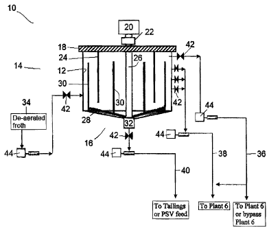
[00026] Figure 2 shows one embodiment of a froth tank (10) useful in the
present
invention which generally defines an inner chamber (12) having a generally
cylindrical upper
portion (14) and a generally conical lower portion (16). A bridge portion (18)
spans across the
upper portion (14) to support a rotary drive assembly (20), a torque sensor
(22), and a plurality of
stationary pickets (24).
[00027] The tank (10) can be open or closed to the external environment. A
roof may be
included to cover the tank (10) to prevent contamination and release of odors,
and to maintain
slurry temperature. Such roofs are typically made from fiberglass plates which
are supported by
the tank (10) and the bridge portion (18).
[00028] The rotary drive assembly (20) includes a motor (not shown)
attached to a drive
gear box (not shown). The motor may be of fixed or variable speed, and use any
suitable motive
power, such as an electric or hydraulic motor or a combustion engine. An
elongate drive shaft
(26) is mounted at a first end in operational engagement with the motor and at
a second end to
the apex of the conical portion (16). The drive shaft (26) is thus mounted in
a substantially
vertical orientation within the inner chamber (12) of the tank (10).
[000291 The drive shaft (26) connects the rotary drive assembly (20) to a
rake assembly
which is mounted for rotation about a generally vertical axis within the
conical portion (16) of
the tank (10). The rake assembly comprises rake arms (28) which are attached
to the drive shaft
(26), and a plurality of generally vertical movable pickets (30) carried by
the rake arms (28).
The rake arms (28) may comprise generally straight or curved blades. The rake
arms (28) are
positioned at the apex of the conical position (16) of the tank (10) to move
settled solids across
the conical portion (16) of the tank (10) for "funnelling" or discharge at a
central underflow
outlet (32). In one embodiment, the slope of the conical portion (16) is about
1:6, i.e., the walls
of the cone are at an angle of about 15 degrees.
[00030] The movable pickets (30) extend parallel to one another
vertically, and are
sufficiently spaced apart to accommodate the downwardly projecting stationary
pickets (24)
therebetween. As the rake arms (28) rotate, the movable pickets (30) travel
around the stationary
pickets (24) through the bitumen froth (34).
WSLegal\053707\00008\7627211v1
CA 02772722 2012-03-26
[00031] As a consequence of its connection to the rake assembly, the drive
shaft (26) is
subjected to very high torques when rotated. The degree of torque is dependent
upon the
resistance to rotation experienced by the drive shaft (26). This resistance
arises primarily as a
result of the rake arms (28) and movable pickets (30) encountering resistance
as they rotate
through the settled solids and bitumen froth, respectively. The torque sensor
(22) is used to
detect the torque exerted upon the drive shaft (26), and transmit signals
representative of the
measured or recorded torque to a controller (not shown). The controller may be
operatively
connected to the motor to control the operation of the drive shaft (26) based
on the signals
received from the torque sensor (22).
[00032] The tank (10) includes an inlet (not shown) through which bitumen
froth (34) is
pumped into the tank (10) above the conical portion (16). The inlet is
oriented tangential to the
tank (10), thereby dampening the turbulence of the incoming bitumen froth (34)
and generating a
swirling flow when feeding the bitumen froth (34) into the inner chamber (12).
Outlets (not
shown) are oriented tangential to the tank (10) to allow the bitumen froth
(36), middlings (38),
and tailings (40) to be separately withdrawn and further processed. In one
embodiment, the
bitumen froth outlet may be a circumferential weir or a surface floating
discharge.
[00033] The tank (10) is interconnected to other components (such as, for
example, valves
(42), pumps (44), and other tanks, tailings ponds or plants) by conduits which
may be
constructed from any suitable piping as is employed in the art. Suitable
piping includes, without
limitation, plastic piping, galvanized metal piping, and stainless steel
piping. The conduits have
associated valves (42) which may be opened and closed to divert the flows of
the separated
bitumen froth, middlings, and tailings among the interconnected components.
The valves (42)
may comprise any suitable valve employed by those skilled in the art to
permit, or prevent, the
flow of the bitumen froth (36), middlings (38), and tailings (40) through a
conduit. Suitable
valves (42) include, but are not limited to, gate valves, butterfly valves,
and ball valves.
[00034] Bitumen froth may contain about 60 wt% bitumen, about 30 wt% water
and about
wt% solid mineral material, of which a large proportion is fine mineral
material. The bitumen
which is present in a bitumen froth comprises both non-asphaltenic material
and asphaltenes.
The bitumen froth (34) is pumped into the froth storage tank (10) above the
conical portion (16)
of the tank (10). A portion of the solids settles during the residence time.
In one embodiment,
the residence time may range from between about two to about twenty-four
hours, preferably
about six to about eighteen hours, and most preferably about two to about four
hours.
VVSLega1\053707\00008\7627211v1
6
CA 02772722 2012-03-26
=
1000351 During the residence time, the motor may be activated
intermittently or
continuously to operate the rotary drive assembly (20) at a desired speed,
thereby rotating the
drive shaft (26) and the rake arms (28). As the rake arms (28) rotate, the
movable pickets (30)
travel around the stationary pickets (24) through the bitumen froth (34),
thereby generating flow
channels which facilitate separation of a top layer of bitumen froth (36), a
middle layer of
middlings (38) (i.e., warm water, fines, residual bitumen), and a bottom layer
of coarse tailings
(40) (i.e., warm water, coarse solids, residual bitumen). The bitumen froth
(36), middlings (38),
and tailings (40) are then separately withdrawn and further processed.
[000361 The upper bitumen-rich, reduced-solids layer (36) overflows the
top of the tank
(10), and is withdrawn for the froth treatment process which eliminates the
aqueous and solid
contaminants from the bitumen froth to produce a clean bitumen product (i.e.,
"diluted bitumen")
for downstream upgrading processes. The bitumen froth is diluted with a
hydrocarbon solvent
(i.e., either a paraffinic or naphthenic type diluent) to reduce the viscosity
and density of the oil
phase, thereby accelerating the settling of the dispersed phase impurities by
gravity or
centrifugation
[00037] The middlings (38) are withdrawn from the mid-section of the
tank upper portion
(14) and pumped to a secondary processing unit.
[000381 The rake arms (28) move the settled solids (40) across the
conical portion (16) of
the tank (10). Since the bottom of the tank (10) is conical shaped, the solids
(40) are easily
discharged downwardly into the central underflow outlet (32) to be withdrawn
as an underflow
and pumped to a tailings pond or secondary processing unit.
[00039] Using the present invention, it was found that the use of the
cone-bottomed froth
storage tank (10) having an internal rake assembly facilitates the storage of
bitumen froth and the
separation of the bitumen froth, middlings, and tailing. Solids may be removed
intermittently or
continuously as warranted during the feed residence time to maintain the
capacity and ability of
the tank (10) to act as a surge vessel. The froth tank capacity is increased
by approximately 25-
30% by eliminating solids accumulations. Further, the tank (10) reduces the
risk of sloughing of
solids into the subsequent froth treatment process. About 30-40% of solids and
15-20% of water
are pre-separated from the bitumen froth and rejected to tailings through the
underflow stream of
the froth tank (10). Higher quality bitumen feed is thus produced for further
upgrading, thereby
minimizing malfunctions in downstream equipment and enhancing the overall
productivity of the
processing plants.
INSLegal\053707\00008\7627211v1
7
CA 02772722 2012-03-26
[00040] By way of example, the middlings stream (38) can be amenable to
further
upgrading, for example, using a two-stage centrifugation process with naphtha
added to reduce
viscosity in a froth treatment plant (Pant 6). Bitumen froth (36) can also be
treated in a froth
treatment plant but may be of sufficient quality (i.e., reduced solids and
water content) that a
froth treatment plant can be bypassed and the bitumen froth (36) can go
directly to upgraders
such as cokers and the like. The tailings (40) may be sufficiently cleaned of
bitumen that the
tailings can be directly deposited in tailings deposit sites. In the
alternative, residual bitumen in
the tailings can be recaptured by recycling this stream back to the primary
separation vessels
(PSVs) where the bitumen froth is originally formed.
[00041] It will be appreciated by those skilled in the art that the tank
(10) of the present
invention may be used to remove solids present in various materials including,
but not limited to,
raw de-aerated bitumen froth; bitumen froth diluted at low (<0.8 w/w) or
normal (0.8 w/w)
naphtha:bitumen ratios; high-density solids/pastes; and the like.
[00092] Exemplary embodiments of the present invention are described in
the following
Examples, which are set forth to aid in the understanding of the invention,
and should not be
construed to limit in any way the scope of the invention as defined in the
claims which follow
thereafter.
[000931 Example 1 ¨ Testing of Cone-Bottomed, Raked Froth Tank
[00044] Pilot tests were conducted to assess the ability of a cone-
bottomed, raked froth
tank to function as a froth cleaner and storage tank; the effects of bulk
froth residence time,
underflow split ratios, and feed compositions on solids/water and bitumen
separation in the froth
tank; and the effect of stationary and movable pickets along with the rake
arms on the separation
of solids/water and bitumen.
[000451 The test conditions are summarized in Table 1:
Waegal\053707\00008\7627211v1
8
CA 02772722 2012-03-26
[00046] Table 1. Test Conditions
Fixed variables Froth temperature: 80 C
Rake turned-on at 1.24 rpm with moving and static pickets
Elevation of feed injection: 1 m above the knuckle
Elevation of middlings withdrawal: 1.5 m above the knuckle
Operating level of froth in the tank: 2 m above the knuckle
De-aerated froth obtained from Aurora froth tank
Independent Bulk froth residence time: 1, 2 and 4 hours by changing feed
flow rates from
variables 3, 1.5 to 0.75 L/s
Underflow split ratios: 3.75%, 7.5%, 15% and 50% by volume
Feed compositions: as is", meaning about 54% bitumen, about 30% water
and about 16% sand (D50300 um)
[00047] The experimental results indicate that the bulk froth residence
time, underflow
split ratio ("U/F," the ratio of the underflow to the feed flow rate), feed
composition, and the use
of pickets had significant effects on the separation between solids/water and
bitumen in the froth
tank.
[00048] The locations of samples withdrawn at different elevations above
the knuckle of
the froth tank are shown in Figure 3. The profiles of the sampled bitumen,
water, solids and
fines at residence times of I, 2 and 4 hours are shown graphically in Figures
4 and 5. The effect
of residence time on underflow component contents is shown in Figures 6A-B.
The effect of
U/F split ratios on underflow component contents is shown in Figures 7A-B. The
effects of feed
composition on underflow component contents when the U/F split ratio is 7.5%,
15% and 50%
are shown in Figures 8A-B, 9A-B, and 10A-B, respectively,
[00049] For the feed "as is, a bulk residence time of 2 to 4 hours and a
maximum U/F
split ratio of 7.5% were required to produce an underflow which could be
rejected as tailings.
The minimum bulk froth residence time in the tank may be 2 hours, but can be
varied between 2
to 24 hours depending upon the froth tank size and the feed rate. The optimal
underflow split
ratio to feed was about 7.5% by volume, but can be varied between 0 to 50% by
volume
depending on the feed froth compositions.
[00050] The use of pickets significantly improved the solids/water and the
bitumen
separation by creating channels within which solids/water easily settled
downward (Figures 11A-
V6Legal\053707\00008\7627211v1
9
CA 02772722 2014-02-21
B). The optimal temperature of the de-aerated bitumen froth fed to the tank
was about 80 C, but
can be varied between about 50 C to 80 C.
[00051] The froth tank was capable of producing a stream with >90%
bitumen, 6% water
and 4% solids from the top of the tank; a middling stream with about 65%
bitumen, 25% water
and 10% solids from the middle of the tank sidewall; and an underflow stream
with about 0.5%
bitumen, 44% water and 55.5% solids from the bottom of the tank. About 35-40%
of the solids
and about 15-20% of the water can thus be removed from bitumen froth before
downstream
processing.
[00052] Example 2 ¨ Specifications for an Exemplary Cone-Bottomed, Raked
Froth
Tank
[00053] A suitable froth tank may be approximately forty meters in
diameter, about
eighteen meters in height, about 23,000 m3 in volume, and have a cone slope of
1:6 in order to
process about 1200 to 3500 m3 per hour of feed, and to ensure the discharge of
solids as tailings.
The residence time may range between about 6 to 18 hours. The froth tank has
an available
volume for feed of about 20,000 m3 and operates at a level between about 15-
90%. The nominal
capacity is about 125 kBBL.
[00054] From the foregoing description, one skilled in the art can easily
ascertain the
essential characteristics of this invention, and without departing from the
spirit and scope
thereof, can make various changes and modifications of the invention to adapt
it to various
usages and conditions. Thus, the present invention is not intended to be
limited to the
embodiments shown herein, but is to be accorded the full scope consistent with
the claims,
wherein reference to an element in the singular, such as by use of the article
"a" or "an" is not
intended to mean "one and only one" unless specifically so stated, but rather
"one or more". All
structural and functional equivalents to the elements of the various
embodiments described
throughout the disclosure that are known or later come to be known to those of
ordinary skill in
the art are intended to be encompassed by the elements of the claims.
Moreover, nothing
disclosed herein is intended to be dedicated to the public regardless of
whether such disclosure is
explicitly recited in the claims.
References
[00055] The following references are indicative of the level of skill of
those skilled in the
art to which this invention pertains.
WSLegA053707\00008\7627211v1
CA 02772722 2012-03-26
Du Toit, W.F. Liquids/solids separator. Canadian Patent Application No.
2,214,538, published
September 26, 1996.
Tipman, R.N., Rajan, V.S.V. and Wallace, E.D. Process for increasing the
bitumen content of
oil sands froth. Canadian Patent No. 2,055,213, issued August 13, 1996.
VVSleg4053707\00008\7627211v1
11