Note: Descriptions are shown in the official language in which they were submitted.
CA 02777282 2012-06-13
VESSEL AND METHOD FOR TRANSPORTING AND
HOISTING THE OFFSHORE WIND TURBINE GENERATOR SYSTEM
FIELD OF THE INVENTION
The present invention relates to a hoisting vessel and a transporting and
hoisting method
using the vessel, and more particularly to a hoisting vessel integrally
transporting and
hoisting the offshore wind turbine, and a transporting and hoisting method
using the
hoisting vessel.
BACKGROUND TO THE INVENTION
In recent years, with the development of wind power technologies and the
gradual
improvement and enhancement of the wind turbines' performance, the wind
turbines are
becoming more and more economic and efficient. The rated power per unit also
augments
constantly. The number and the coverage area of the wind turbines are
gradually reduced
under the same installed capacity, and the investment of the infrastructure is
enormously
saved accordingly. However, with further development of the wind power
industry, the
development of the onshore wind farms has been saturated day by day. Moreover,
while the
rated power per unit of the wind turbines is gradually magnified, the length
and the weight
of each part of the wind turbines are constantly augmented. Then the
difficulty and the cost
of transporting and installing the wind turbines are greatly increased. In
comparison, wind
farms on the sea (offshore wind farms) have the advantages of higher wind
speed, lower
turbulence, and lower wind shear and so on. Offshore wind turbines have the
features of
longer rotor diameter, lower rated wind speed, lower wheel hub height (lower
tower barrel
height), and higher blade tip velocity ratio under the same rated power. By
this way, the
power output from the wind turbines can be enhanced greatly, and the service
life of the
wind turbines can be extended enormously. Nowadays, offshore wind power is
developing
rapidly in many countries of the world, and domestic 10,000,000 kilowatt-level
offshore
wind farms are also planned.
1
CA 02777282 2012-06-13
= However, it is a big challenge to install the wind turbines on the sea (the
offshore wind
turbines), and their construction process is severely influenced by wind and
wave.
At present, installing solutions of the overseas offshore wind farms comprise:
(1) By-parts
assembling: In a similar manner to the installing solutions of the onshore
wind turbines, the
tower barrel, the nacelle and the rotor blades are installed successively into
the wind farms.
The hoisting vessels integrally jack them above the surface of the water, to
avoid their
heave and pitch aroused by wind and wave, so as to install the wind turbines
safely and
precisely. (2) Integrally hoisting: After the wind turbines are assembled in
dock, they are
integrally hoisted onto the installing vessel, transported to the wind farms,
and integrally
hoisted. Because at present this type of integrally hoisting is floating
hoisting without
exception, docking the wind turbines to the foundation should use buffering
measures to
protect the foundation and the wind turbines.
There have not been any mature special devices for installing the offshore
wind turbines in
domestic. Therefore hoisting devices will certainly become the bottleneck of
the
development of the offshore wind power, as far as the offshore wind power in
domestic is
concerned.
OBJECTS OF THE INVENTION
To overcome the limitations of existing solutions of by-parts hoisting and
integrally
hoisting, so as to enhance the economy and safety of the wind farms'
construction, and to
shorten the building period and device commissioning period of the offshore
wind farms,
the present invention provides a vessel for integrally transporting and
hoisting the offshore
wind turbine, and a transporting and hoisting method using the vessel, which
could enable
the wind turbine to be integrally transported and hoisted. The present
invention could not
only ensure that the devices of the wind turbine are commissioned sufficiently
before being
hoisted, but also could transport and hoist the offshore wind turbine
economically and
efficiently. The present invention not only greatly shortens the period for
constructing the
wind farms, but also reduces the commissioning work after hoisting the wind
turbine.
Rapid grid-connection of the offshore wind turbine is realized also.
2
CA 02777282 2012-06-13
SUMMARY OF THE INVENTION
The present invention provides a vessel for transporting and hoisting the
offshore wind
turbine, comprises: a hull, with a U-shaped opening for a wind turbine to pass
through at
the stern of the hull; a plurality of fixing brackets, which are arranged in
two rows in
parallel, the bottom of which are fixed onto the deck in the hull; first
sliding rails, which are
installed on the top of each row of the fixing brackets; second sliding rails,
which are
installed on the inner side of the two rows of the fixing brackets on the deck
of the hull, and
are in parallel with the first sliding rails; the wind turbine, with a hanging
beam slidably
matched with the first sliding rails on the body of the wind turbine; a buffer
device, which
is fixed onto the bottom of the wind turbine, and is slidably matched with the
second
sliding rails; rotary cranes, which are fixed on the top of the two sides of
the U-shaped
opening; winch devices, which are installed on the stern of the hull.
Preferably, the buffer device has a plurality of claws, with a hydraulic
cylinder on the
bottom of each claw.
Preferably, symmetrical wings are provided in the two sides of the hanging
beam, and the
wings lie on the first sliding rails.
Preferably, the winch device has a steel cable, one end of which is fixed on
said winch
device, the other end of which is fixed on said hanging beam of the wind
turbine.
Preferably, winch devices are also provided at the fore of the hull.
Preferably, fixed pulleys are provided at the fore of the hull for the steel
cable to wind on.
Also, the present invention provides a method for transporting and hoisting
the offshore
wind turbine using foresaid vessel for transporting and hoisting the offshore
wind turbine,
comprising the following steps: assembling the wind turbines and executing
grid-
connection test; (2) integrally loading the wind turbines one by one; (3)
transporting the
hoisting vessel on the sea to a given wind farm position;(4) hoisting the wind
turbine above
3
CA 02777282 2012-06-13
the foundation of the wind turbine, and stably docking the wind turbine to the
foundation of
the wind turbine via the buffering of the buffer device.
Preferably, the step (2) further comprises: turning around the rotary cranes
afterthe hanging
beam of the wind turbine has been hoisted, and uplifting the wind turbine onto
the deck in
the hull, making the first sliding rails slidably matched with the hanging
beam and the
buffer device slidably matched with the second sliding rails; fastening the
steel cables of
the winch device at the fore onto the hanging beam of the wind turbine, and
tightening the
steel cables by the winch device at the fore to translate the complete machine
of the wind
turbine on the vessel, thereby to move the wind turbine to a given position.
Preferably, the step (2) further comprises: turning around the rotary cranes
afterthe hanging
beam of the wind turbine has been hoisted, and uplifting the wind turbine onto
the deck in
the hull, making the first sliding rails slidably matched with the hanging
beam and the
buffer device slidably matched with the second sliding rails; winding the
steel cables of the
winch device at the stem on the fixed pulleys at the fore, fixing the end of
the steel cables
on to the hanging beam of the wind turbine, and tightening the steel cables by
the winch
device at the stem to translate the complete machine of the wind turbine on
the vessel,
thereby to move the wind turbine to a given position.
Preferably, the step (4) further comprises: fastening the steel cables of the
winch device at
the stern on the hanging beam of the wind turbine, translating the wind
turbine into the
range of the working radius of the rotary cranes by the retraction of the
winch device at the
stem, and then unrigging the steel cables, turning around the rotary cranes
after they uplift
the hanging beam of the wind turbine, and hoisting the wind turbine above the
foundation
of the wind turbine.
The beneficial technical effects of the present invention are: realizing
transporting and
hoisting a plurality of sets of wind power turbines in one vessel, providing a
novel
construction solution for offshore wind power; realizing sufficiently
commissioning the
wind turbines before the delivery, greatly shortening the time for on-the-
field
commissioning; reducing the wind power installing vessels' restrictions on the
outside
conditions such as sea bed and depth of water etc. The present invention not
only could
4
CA 02777282 2012-06-13
perform the construction for offshore wind farms, but also could execute the
construction
for deep sea wind farms. The present invention is safe, efficient, and
economy. It greatly
shortens the delivery period of the wind power devices, and makes the devices
more
competitive.
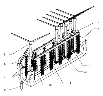
BRIEF DESCRIPTION OF THE DRA WINGS
FIG. 1 is a graph integrally illustrating the transporting and hoisting vessel
of the present
invention;
FIG. 2 is the top view of loading the wind turbine and translating the wind
turbine of the
present invention;
FIG. 3a and 3b are graphs illustrating the movements of hoisting and
installing the wind
turbine of the present invention.
Brief description of the drawing reference signs: fixing brackets-1; hanging
beam-2; first
sliding rails-31; second sliding rails-32; winch devices-4; buffer device-5;
rotary crane-6;
hull-7; wind turbine-8; foundation of a wind turbine-9; dock- 10.
DETAILED DESCRIPTION OF THE INVENTION
The following preferred embodiments with reference to the accompanying
drawings are
provided in detail to assist in a comprehensive understanding of the shape,
the structure and
the feature of the invention.
FIG. 1 is a graph integrally illustrating the transporting and hoisting vessel
of the present
invention. As shown in FIG. 1, the present invention provides a vessel for
transporting and
hoisting the offshore wind turbine comprises: a hull 7, with a group of
hoisting devices in
the hull. Said hoisting devices comprise a group of fixing brackets 1, which
are a plurality
of fixing brackets I arranged in two rows in parallel. The bottom of the
fixing brackets I is
5
CA 02777282 2012-06-13
fixed onto the deck in the hull 7. A steel structure is fixed on the top of
the fixing brackets
1. A first sliding rail 31 is separately installed on each of the two rows of
the steel structure.
Two second sliding rails 32 are installed on the inner side of the two rows of
fixing
brackets 1 on the deck in the hull 7, and are in parallel with the first
sliding rails 31.
The wind turbine 8 is a complete machine that is assembled, which comprises
the
components such as the body of the wind turbine and the rotor blades. The
structure of the
wind turbine 8 is not the inventive point of the present invention, so
unnecessary details are
not incorporated herein. A hanging beam 2 is installed on the body of the wind
turbine 8
and is slidably matched with the first sliding rails 31. Symmetrical wings are
provided in
the two sides of the hanging beam 2, can lie on the first sliding rails 31,
and slide on the
first sliding rails 31.
A buffer device 5 is fixed onto the bottom of wind turbine 8 via the bolts and
lie on the
second sliding rails 32. A matching mechanism matching with the sliding rails
is provided
on the bottom of the buffer device 5, so as to make the buffer device 5
slidably matched
with the second sliding rails 32. The wind turbine 8 could conveniently move
in the hull 7
by matching the hanging beam 2 with the first sliding rails 31 and matching
the buffer
device 5 with the second sliding rails 32.
The buffer device 5 has a plurality of claws, with a hydraulic cylinder on the
bottom of
each claw. When the wind turbine 8 is landed onto a foundation of the wind
turbine 9
where the wind turbine is required to be installed, the impact force between
the wind
turbine 8 and the foundation of the wind turbine 9 is buffered by the
hydraulic cylinder, so
as to protect the wind turbine 8.
Two winch devices 4 are provided at the stem of the hull 7. Each winch device
4 comprises
a strip of steel cable. One end of the steel cable is fixed onto said winch
device 4, the other
end of the steel cable is fixed on to the hanging beam 2 of the wind turbine 8
which would
be towed. When the winch devices 4 is wound, the steel cable is tightened,
thereby tows the
wind turbine 8 sliding from the fore to the stern. The complete machine of the
wind turbine
8 is translated.
6
CA 02777282 2012-06-13
Two winch devices 4 can be provided at the fore too, to translate the complete
machine of
the wind turbine 8 from the stern to the fore while loading the wind turbine
8. The structure
and the working principle of the winch device 4 at the fore are the same as
the counterparts
of the stern, so unnecessary details are not incorporated.
Said two winch devices 4 at the fore can be substituted by two fixed pulleys.
That is to say,
two fixed pulleys are set symmetrically at the fore; the steel cables of the
winch device 4 at
the stern are wound on the fixed pulleys at the fore, and then fixed on the
hanging beam 2
of the wind turbine 8. When the wind turbine 8 is being loaded, the winch
device 4 at the
stem is winding; the steel cables are wound through the fixed pulleys at the
fore, and
translate the complete machine of the wind turbine 8 by towing it from the
stern to the fore.
In this way, the same winch device 4 can be used to wind and move the wind
turbine 8 in
two directions.
A U-shaped opening is provided at the stern for the wind turbine 8 to pass
through. A
rotary crane 6 is provided on the top of the two sides of the U-shaped
opening. When the
complete machine of the assembled wind turbine 8 is loaded, each of the two
rotary cranes
6 separately hoists the wings of the two sides of the hanging beam 2, hoists
the wind
turbine 8 from the U-shaped opening into the hull 7, and then lands it onto
the sliding rails.
When the wind turbine 8 is required to be unloaded, by the same token, after
the wind
turbine 8 is uplifted by the rotary crane 6, the rotary crane 6 turns around
and the wind
turbine 8 is unloaded from the interior of the hull 7.
FIG. 2 is the top view of loading the wind turbine and translating the wind
turbine of the
present invention; FIG. 3a and 3b are graphs illustrating the movements of
hoisting the
wind turbine of the present invention. As show in the figures, the present
invention
provides a method for transporting and hoisting offshore wind turbine achieved
by using
foregoing transporting and hoisting vessel. Its detailed implementing methods
are as
follows:
First, the wind turbines 8 are assembled in the dock 10, and the grid-
connection test is
executed. And then the wind turbines 8 are unloaded one by one from the
foundation of the
wind turbine 9 in the dock 10, and are integrally loaded. Details are
incorporated herein.
7
CA 02777282 2012-06-13
After two rotary cranes 6 on the transporting and hoisting vessel hoist the
hanging beam 2
of the wind turbine 8, they turn around, and uplift the wind turbine 8 onto
the deck in the
hull 7, making the first sliding rails 31 slidably matched with the hanging
beam 2 and the
buffer device 5 slidably matched with the second sliding rails 32.
The steel cables of the winch device 4 at the fore are fixed onto the hanging
beam 2 of the
wind turbine S. The steel cables are tightened by the winch device 4 at the
fore, to translate
the complete machine of the wind turbine 8 on the vessel, thereby to move the
wind turbine
8 from the stem toward the fore to a given position. Alternatively, steel
cables of the winch
device 4 at the stern are wound on the fixed pulleys set at the fore, and then
fixed onto the
hanging beam 2 of the wind turbine 8. The steel cables are tightened by the
winch device 4
at the stern, turn around via the fixed pulleys, and move the wind turbine 8
from the stem to
a given position of the fore.
After all of the wind turbines 8 are loaded and fixed, the loading work of the
wind turbines
8 is accomplished. After the wind turbines 8 being loaded, they are
transported on the sea
to a given wind farm location with the hoisting vessel. After the hoisting
vessel is precisely
positioned, it is ballasted to prepare to hoist the complete machine of the
wind turbine 8.
In the process of hoisting, the steel cables of the winch devices 4 are fixed
on the hanging
beam 2 of the wind turbine 8. The winch devices 4 retract to translate the
wind turbine 8
into the range of the working radius of the rotary cranes 6. Thereafter, the
steel cables are
unrigged. After the rotary cranes 6 uplift the hanging beam 2 of the wind
turbine 8, the
rotary cranes 6 turn around, and the wind turbine 8 is hoisted above the
foundation 9 of the
wind turbine. The wind turbine 8 is stably docked to the foundation of the
wind turbine 9
via the buffering of the buffer device 5. And then the hoisting vessel moves
to the next
position to hoist the next wind turbine 8.
The present invention provides a vessel for transporting and hoisting the
offshore wind
turbine. The beneficial technology effect achieved by the foregoing technical
solution is
enabling the wind turbine to be integrally transported and hoisted. The
present invention
could not only ensure that the wind turbines is sufficiently commissioned
before the
hoisting, but also could transport and hoist the offshore wind turbine
economically and
8
CA 02777282 2012-06-13
efficiently. The present invention not only shortens the building period of
the wind farms
greatly, but also reduces the commissioning work after hoisting the wind
turbine, to realize
the rapid grid-connection test of the offshore wind turbine. The present
invention realizes
transporting and hoisting a plurality of sets of wind turbines in one vessel,
provides a novel
construction solution for offshore wind power; realizes sufficiently
commissioning the
wind turbines before the delivery, and greatly shortens the time for on-the-
field
commissioning; reducing the wind power installing vessels' restriction on the
outside
conditions such as sea bed and depth of water etc. The present invention not
only could
perform the construction for offshore wind farms, but also could execute the
construction
for deep sea wind farms. The present invention is safe, efficient, and
economy. It greatly
shortens the delivery period of the wind power devices, and makes the devices
more
competitive.
It will be appreciated that the foregoing descriptions of the present
invention are
illustrative, but not restrictive for the ordinary skilled person in the art.
Within the scope
and spirit of the claims of the present invention, a plurality of
modifications, changes, or
equivalences could be made without departing from the scope and spirit of the
invention.
9