Note: Descriptions are shown in the official language in which they were submitted.
CA 02858344 2014-08-01
Drywall tape dispenser actuated using a drill
FIELD OF THE INVENTION
[001] The present invention relates generally to drywall tools but more
particularly to a drywall tape dispenser actuated using a drill.
BACKGROUND OF THE INVENTION
[002] Drywalling requires putting tape on all the joints. There are different
methods that have been used over the years. One consists in applying
wet plaster over the joints and then pressing a dry paper ribbon over
and removing excess plaster with a trowel. Another technique involves
getting the tape saturated with wet plaster so that it can be applied over
the joints in a single operation. Both methods are rather tedious and can
be quite messy. There is a need for a better way to do this job.
15SUMMARY OF THE INVENTION
[003] In view of the foregoing disadvantages inherent in the known devices
now present in the prior art, the present invention, which will be
described subsequently in greater detail, is to provide objects and
advantages which are:
CA 02858344 2014-08-01
2
[004] To provide for a quick and simple method of applying a dry ribbon over a
plastered joint.
[005] In order to do so, the invention has an "L" shaped member having a top
cross piece, an elongated side piece, and an elbow portion
therebetween thereby forming an L-shape, a first spindle member at a
bottom portion of the elongated side piece, a second spindle member at
a top portion of the elongated side piece and within the elbow portion,
and a third spindle member between the first and second spindle
members.
10[006] An active pressure roller rotatably attached to a distal end section
of the
top cross piece opposite the elbow portion adapted to press on a
surface portion of tape passing thereby. A passive pressure roller
rotatably attached to the distal end section of the top cross piece
opposite the elbow portion and spaced from the active pressure roller
and adapted to press on an opposite surface portion of the tape passing
thereby, such that the active pressure roller and the passive pressure
roller are adapted to pinch the tape passing therethrough.
[007] A sub- frame connector member attached to and extending outwardly
from the elongated side piece and parallel to the top cross piece, and
including a tape holding member adapted to rotatably hold a roll of tape
thereon. A drill connector attached to the active pressure roller and
CA 02858344 2014-08-01
1
adapted to connect to a drill member, such that the drill member can
rotate the active pressure roller, such that when the tape is looped
around the second spindle member, then down and around and up from
the first spindle member, then around the third spindle member, and
then between the active and passive pressure rollers, the tape is
dispensed from the dispenser and onto a chosen surface.
[008] Preferably, a distal end of the sub-frame connector member spaced
from the side piece of the "L" shaped member is connected to the distal
end section of the top cross piece by an elongated sub-frame connector
member.
[009] The "L" shaped member and the sub-frame connector member are both
formed using elongated, flat, spaced parallel frame portions, to thereby
provide space within the "L" shaped members for the spindle members
and the tape to pass thereth rough.
15[0010] In a preferred embodiment, the drywall tape dispenser is further
comprised of a fourth spindle member located at the distal end of the
top cross piece, and adapted to guide the tape into and through the
active and passive pressure rollers.
[0011] The active pressure roller is rotatably attached to the distal end
section
of the top cross piece via at least one spring biased arm, and at least
CA 02858344 2014-08-01
2
one spring member attached between each the at least one spring
biased arm, such that pressure is applied between the active and
passive pressure rollers to thereby be adapted to pull the tape
therebetween and therethrough when the drill connector is rotated by
the drill member.
[0012] In yet another preferred embodiment, there are two spring biased arms
respectively attached to opposite sides of the active pressure roller and
to the distal end of the top cross piece.
[0013] The passive pressure roller is connected to the distal end section of
the
top cross piece by an elongated passive pressure roller connector
member, to thereby position the passive pressure roller such that the
tape is adapted to pass between and through the active and passive
pressure rollers in a direction that allows the tape to contact be directed
by the fourth spindle member before being dispensed from the
dispenser.
[0014] Preferably, the tape holding member is removably attached to the sub-
frame member by being formed in a nut and bolt configuration, such that
when the tape runs out a new roll of tape can be easily inserted into the
tape dispenser.
CA 02858344 2014-08-01
3
[0015] The dispenser is formed from a list of non-corrosive materials
comprising stainless steel, plastic, and composite plastics.
[0016] The drywall tape dispenser is used in combination with a roll of tape
and
a drill member.
5[0017] There has thus been outlined, rather broadly, the more important
features of the invention in order that the detailed description thereof
that follows may be better understood, and in order that the present
contribution to the art may be better appreciated. There are additional
features of the invention that will be described hereinafter and which will
form the subject matter of the claims appended hereto.
[0018] In this respect, before explaining at least one embodiment of the
invention in detail, it is to be understood that the invention is not limited
in its application to the details of construction and to the arrangements
of the components set forth in the following description or illustrated in
the drawings. The invention is capable of other embodiments and of
being practiced and carried out in various ways. Also, it is to be
understood that the phraseology and terminology employed herein are
for the purpose of description and should not be regarded as limiting.
[0019] As such, those skilled in the art will appreciate that the conception,
upon
which this disclosure is based, may readily be utilized as a basis for the
CA 02858344 2014-08-01
4
designing of other structures, methods and systems for carrying out the
several purposes of the present invention. It is important, therefore, that
the claims be regarded as including such equivalent constructions
insofar as they do not depart from the spirit and scope of the present
invention.
[0020] These together with other objects of the invention, along with the
various
features of novelty which characterize the invention, are pointed out with
particularity in the claims annexed to and forming a part of this
disclosure. For a better understanding of the invention, its operating
advantages and the specific objects attained by its uses, reference
should be made to the accompanying drawings and descriptive matter
which contains illustrated preferred embodiments of the invention.
15BRIEF DESCRIPTION OF THE DRAWINGS
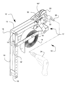
[0021] Fig. 1 Isometric view of the invention.
[0022] Figs. 2 a-b Top and side views of the invention.
[0023] Fig. 3 Side view showing the path and direction of the tape.
CA 02858344 2014-08-01
DETAILED DESCRIPTION OF THE PREFERRED EMBODIMENT
[0024] A drywall tape dispenser (10) has an "L" shaped member (12) consisting
of a top cross piece (13), an elongated side piece (15), and an elbow
5 portion (19) therebetween thereby forming an L-shape. A tape holding
member (16) onto which is installed a roll of tape (14). The tape (14) is
dispensed over first, second, third, and fourth spindle members (18, 18',
18", 18-) forming part of the "L" shaped member (12). The tape (14) then
passes between an active pressure roller (20) and a passive pressure
roller (22). The active presure roller (20) is actuated by a drill (24) by way
of a drill connector (26). The tape holding member (16) is itself being
held by a sub-frame connector member (17) which is fixedly attached to
the "L" shaped member (12).
[0025] The tape dispenser (10) is held by a user who moves it in such a way
that the passive pressure roller (22) rolls over a joint so that the tape
(14), exiting between both the active and passive rollers (20, 22), can be
applied. The "L" shaped member (12) and the sub-frame connector
member (17) are both formed using elongated, flat, spaced parallel
frame portions, to thereby provide space for the spindle members (18,
18', 18") and the tape (14) to pass therethrough.
CA 02858344 2014-08-01
1
[0026] Other parts include a cover member (28) to protect the tape (14) from
falling plaster. At least one spring (30) to apply pressure between the two
pressure roller (20, 22).
[0027] The active pressure roller (20) connects with the spring (30) by way of
a
lever arm member (32) which is designed to be axially movable around
an axis defined by the location of the coiled section of the spring (30).
This ensures that a constant pressure is applied by the active roller (20)
onto the passive roller (22) such that the tape (14) can be pulled through.
[0028] As to a further discussion of the manner of usage and operation of the
present invention, the same should be apparent from the above
description. Accordingly, no further discussion relating to the manner of
usage and operation will be provided.
[0029] With respect to the above description then, it is to be realized that
the
optimum dimensional relationships for the parts of the invention, to
include variations in size, materials, shape, form, function and manner of
operation, assembly and use, are deemed readily apparent and obvious
to one skilled in the art, and all equivalent relationships to those
illustrated in the drawings and described in the specification are
intended to be encompassed by the present invention. Therefore, the
foregoing is considered as illustrative only of the principles of the
invention. Further, since numerous modifications and changes will
CA 02858344 2014-08-01
2
readily occur to those skilled in the art, it is not desired to limit the
invention to the exact construction and operation shown and described,
and accordingly, all suitable modifications and equivalents may be
resorted to, falling within the scope of the invention.