Note: Descriptions are shown in the official language in which they were submitted.
CA 02877501 2014-12-19
WO 2013/192096 PCT/US2013/046149
A METHOD FOR DETERMINING AN EQUIPMENT CONSTRAINED ACQUISITION
DESIGN
CROSS-REFERENCE TO RELATED APPLICATIONS
[0001]
This application is a non-provisional application which claims benefit under
35 USC
119(e) to U.S. Provisional Application Ser. No. 61/663,113 filed June 22,
2012, entitled "A
METHOD FOR DETERMINING AN EQUIPMENT CONSTRAINED ACQUISITION
DESIGN," which is incorporated herein in its entirety.
FIELD OF THE INVENTION
[0002]
This invention relates to a method for determining an equipment constrained
acquisition design.
BACKGROUND OF THE INVENTION
[0003]
Seismic surveying is used for determining the structure of subterranean
strata.
Seismic surveying typically uses a seismic energy source, such as airguns,
explosive charges or
mechanical vibrators, and seismic receivers, such as hydrophones, geophones or
accelerometers.
The seismic energy source generates acoustic waves which propagate through the
subterranean
strata and reflect from acoustic impedance differences generally at the
interfaces between strata.
The reflected waves are detected by the seismic receivers, which generate
representative
electrical signals. The resulting signals are stored locally and collected
later or transmitted by
electrical, optical, or radio telemetry to a location where the signals are
recorded for later
processing and interpretation. The measured travel times of the reflected
waves from the source
to the receiver locations and the characteristics of the received energy, such
as amplitude,
provide information concerning the subterranean strata. Seismic surveys are
interpreted to
determine the most suitable locations for drilling wells for production of
hydrocarbons.
[0004]
The seismic receivers detect noise from many sources known in the art, and
detect
multiple reflections, as well as the primary reflected waves which are of
interest in determining
the subsurface structures. The noise and multiple reflections obscure the
desired signal and
complicate the process of seismic data analysis. A common technique for
enhancing the signal-
to-noise and primary-to-multiple ratios is the use of multiple different
samples of the data. These
many samples are called "multi-fold" data. This technique activates the
seismic source at a
CA 02877501 2014-12-19
WO 2013/192096 PCT/US2013/046149
plurality of locations for detection by multiple seismic receivers. The
seismic signals received
over time are "gathered" by identifying those seismic signals or "traces"
corresponding to the
same subsurface reflection point, such as a common depth point (CDP) or a
common midpoint
(CMP). The traces in each CDP/CMP gather are normally "stacked". Stacking is
the process of
summing together the traces so that the coherent primary signal is enhanced by
in-phase addition
while source-generated and ambient noise is attenuated by destructive
interference. The number
of traces in each common point gather is termed the fold or multiplicity of
the data.
[0005] Two-dimensional (2-D) seismic surveys typically utilize a simple
linear recording
geometry. A receiver "group" of one or more receivers is positioned at each
receiver station, or
location, and the receiver locations are arranged in a single line. The
receiver locations are
typically equally spaced along the receiver line, giving a constant group
interval, or spacing,
between receiver locations. The source stations or locations are generally
collinear or parallel to
the receiver line and by convention are normally spaced between the receivers.
Multiple fold
data is obtained by moving the source location relative to the receiver line
so as to maintain a
common depth point for multiple pairs of source and receiver locations. The
source locations are
typically equally spaced, giving a constant source interval or spacing between
source locations.
[0006] Three-dimensional (3-D) seismic surveys utilize more complex
recording
geometries. 3-D recording geometries known in the art typically use multiple
nominally parallel
receiver lines of seismic receivers, typically with the receiver locations
equally spaced along the
receiver lines and the receiver lines equally spaced from each other. Source
locations are
typically positioned along source lines and typically are evenly spaced. The
source lines are
typically orthogonal to the receiver lines, but may also be parallel to or at
a diagonal angle,
typically 45 or 22.5 degrees, to the receiver lines. In 3-D surveys, gathers
are constructed by
taking all seismic traces from an area, referred to as a "bin", around each
common midpoint and
assigning the traces to that common midpoint. The areal dimensions of the bin
are generally half
the group interval by half the source interval. The size of the source
interval is independent of the
size of the group interval, allowing the use of rectangular bins rather than
square bins. Seismic
recording methods using these geometries are generally termed "swath" methods.
After data are
recorded along one swath, one or more of the receiver lines are picked up and
replaced on the
other side of the recording spread to be used in the next swath, a process
termed rolling, rolling
along, or rolling over. A uniform fold, in which each rollover develops the
same positive integer
2
CA 02877501 2014-12-19
WO 2013/192096 PCT/US2013/046149
value for multiplicity, is termed an even fold. Maintaining an even fold
constrains the number of
receiver lines recorded, the number of receiver lines which are rolled over
each time, and the
location of sources relative to the receiver spread. Increasing the fold
requires increasing the
number of receiver lines or decreasing the source line interval, thus
increasing the number of
source locations. The maximum offset, which depends on the depth of the
deepest targets that
must be imaged, is the maximum distance between receiver and source in the
spread.
Maintaining a maximum offset constrains the location of sources relative to
the receiver spread.
Increasing the maximum offset requires increasing the source spread coverage
relative to
receiver spread which increases the fold as well.
[0007] There is a disadvantage to this kind of 3-D shooting, however, in
the excessive
amount of equipment required to source on a grid interval equal to twice the
desired subsurface
resolution. Accordingly, if use of 3-D seismic surveys is to continue to grow,
a need exists for
new and improved methods that simplify and/or provide economical alternatives
that reduce the
operational costs of obtaining 3-D seismic survey data.
SUMMARY OF THE INVENTION
[0008] In an embodiment, a method for determining an equipment
constrained
acquisition design, wherein the method includes: (a) providing a plurality of
seismic receiver
lines in a parallel arrangement; providing a plurality of seismic sources,
wherein the plurality of
seismic sources are in range of the plurality of seismic receiver lines; (c)
determining the length
of each seismic receiver line, wherein the length of each seismic receiver
line is substantially
similar; (d) determining a seismic receiver line interval, wherein the seismic
receiver line
interval is the distance between seismic receiver lines; (e) determining a
maximum offset,
wherein the maximum offset is the distance between the seismic receiver and
the seismic source;
(f) determining the number of zippers; (g) determining a seismic receiver
coverage length,
wherein the seismic receiver coverage length is determined by establishing a
relationship
between the total number of seismic receiver lines, the length of the seismic
receiver lines and
the number of zippers, wherein the relationship provides
R = imL
3
CA 02877501 2014-12-19
WO 2013/192096 PCT/US2013/046149
in which R = seismic receiver coverage, m = the number of seismic receiver
lines, L = the length
of the seismic receiver line, and i = the number of zippers; (h) determining
the seismic source
coverage, wherein the seismic source coverage is determined by establishing a
relationship
between the length of the seismic receiver lines, the maximum offset, the
seismic receiver line
intervals, the number of seismic receiver lines, and the number of zippers,
wherein the
relationship provides
S = (2b + (mi ¨ 1)t)(L + (2i ¨ 1)b)
in which S = seismic source coverage, b = the maximum offset, and t = the
seismic receiver line
interval; and (i) determining the seismic source coverage per unit seismic
receiver coverage
length, wherein the seismic source coverage per unit seismic receiver coverage
length is
determined by establishing a relationship between the seismic receiver
coverage length and the
seismic source coverage, wherein the relationship provides
a.
in
R
in which a = the seismic source coverage per unit seismic receiver coverage
length.
BRIEF DESCRIPTION OF THE DRAWINGS
[0009] The invention, together with further advantages thereof, may best
be understood
by reference to the following description taken in conjunction with the
accompanying drawings
in which:
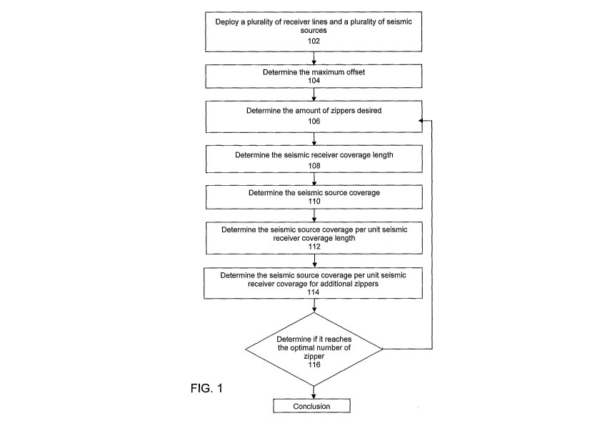
[0010] FIG. 1 is a flow chart describing an embodiment of the present
invention.
[0011] FIG. 2 is a schematic of one swath in accordance with an
embodiment of the
present invention.
[0012] FIG. 3 is a schematic of two zippers in accordance with an
embodiment of the
present invention.
[0013] FIG. 4 is a schematic of three zippers in accordance with an
embodiment of the
present invention.
[0014] FIG. 5 is a schematic of four zippers in accordance with an
embodiment of the
present invention.
4
CA 02877501 2014-12-19
WO 2013/192096 PCT/US2013/046149
DETAILED DESCRIPTION OF THE INVENTION
[0015] Reference will now be made in detail to embodiments of the present
invention,
one or more examples of which are illustrated in the accompanying drawings.
Each example is
provided by way of explanation of the invention, not as a limitation of the
invention. It will be
apparent to those skilled in the art that various modifications and variations
can be made in the
present invention without departing from the scope or spirit of the invention.
For instance,
features illustrated or described as part of one embodiment can be used on
another embodiment
to yield a still further embodiment. Thus, it is intended that the present
invention cover such
modifications and variations that come within the scope of the appended claims
and their
equivalents.
[0016] The fundamental problem facing the seismic designer given a
limited number of
receivers and a large surface area to cover is how to roll the equipment from
swath to swath.
Particularly, this is a problem in marine ocean bottom cable (OBC) and ocean
bottom node
(OBN) surveys where the number of available channels is limited when compared
to land. The
designer is typically given two major choices: (1) roll the swath inline or
roll the swath crossline
and (2) how many zippers or overlaps between swaths are desired. The number of
zippers or
overlaps is a function of the amount of equipment available and the number of
lines of receivers
which can be deployed versus the number of zippers needed to complete the
survey. The impact
of these decisions is the total time to acquire the survey. Because an OBN/OBC
crew costs
around $1 to $2 per second these decisions have major financial impacts on the
total survey
costs.
[0017] Industry convention is to avoid zippers because they are perceived
to take longer
than swaths. Most OBN/OBC surveys are designed using this paradigm and
approach. The
problem is that this is based upon industry convention and not rigorously
developed or analyzed.
[0018] FIG. 1 is a flow chart representing a particular embodiment of the
present
invention illustrated in FIG. 1. In alternative implementations, the functions
noted in the various
blocks may occur out of the order depicted in FIG. 1. For example, two blocks
shown in
succession in FIG. 1 may in fact be executed substantially concurrently, or
the blocks may
sometimes be executed in the reverse order depending upon the functionality
involved.
[0019] In step 102, a plurality of receiver lines and a plurality of
seismic sources are
deployed. The seismic receiver lines are normally deployed in a parallel
arrangement. The
CA 02877501 2014-12-19
WO 2013/192096 PCT/US2013/046149
seismic receiver lines are normally equally spaced apart with substantially
similar lengths but in
an alternative embodiment, non-equidistant receiver lines can be analyzed. The
source lines are
normally orthogonal or parallel to the receiver lines.
[0020] In step 104, the maximum offset is determined. The maximum offset
is the
maximum distance between the seismic receiver and the seismic source. The
maximum offset is
generally a design criteria based upon the geophysical objectives of the
survey planned.
However, there are many different techniques for determining maximum offset
which should be
considered before the final determination is made by the survey designer.
[0021] In step 106, the amount of zippers desired is determined. Start
with one zipper,
then gradually increase the number of zippers until the optimum number of
zippers is achieved.
[0022] In step 108, the seismic receiver coverage length is determined.
The seismic
receiver coverage length is determined by establishing a relationship between
the total number of
receiver lines, the length of a single receiver line and the number of
zippers:
R = imL
where R = seismic receiver coverage length, m = the number of seismic receiver
lines, L = the
length of a single seismic receiver line, and i = the number of zippers.
[0023] In step 110, the seismic source coverage is determined. The
seismic source
coverage is determined by establishing a relationship between the length of a
single seismic
receiver line, the maximum offset, the distance between seismic receiver
lines, the number of
seismic receiver lines and the number of zippers providing:
S = (2b + (mi ¨1)t)(L + (2i ¨1)b)
where S = seismic source coverage, b = the maximum offset, and t = the
distance between
seismic receiver lines.
[0024] In step 112, the seismic source coverage per unit seismic receiver
coverage length
is determined. The seismic source coverage per unit seismic receiver coverage
length is
determined by establishing a relationship between the seismic source coverage
and the seismic
receiver coverage length providing:
a.
where
R
where a = the seismic source coverage per unit seismic receiver coverage
length.
6
CA 02877501 2014-12-19
WO 2013/192096 PCT/US2013/046149
[0025] The durance of a survey is mainly determined by the number of
total shots. The
cost of an OBN/OBC crew is a linear function with time. Therefore, given a
certain amount of
equipment, the smallest source coverage which means the least number of total
shots is the most
cost-efficient survey design. In step 116, based on the criteria, evaluate if
the number of zippers
reaches the optimal number of zippers, otherwise increase the number of
zippers and re-calculate
the seismic source coverage per unit seismic receiver coverage length for
additional zippers (step
114).
[0026] For more in depth analysis, FIGS. 2-5 investigate the use of
seismic survey
equipment for a plurality of zippers concluding with a universal formula. FIG
2 depicts a seismic
survey containing one swath 200 with a plurality of parallel seismic receiver
lines equally spaced
with substantially similar lengths, collectively 204. The seismic source
coverage is depicted by
202 which extends the receiver coverage about half distance of maximum offsets
along the
receiver direction and the distance of maximum offset perpendicular to the
receiver line
direction. The seismic receiver coverage length (R1) for one swath is
determined by establishing
a relationship between the number of seismic receiver lines (m) and the length
of a single
seismic receiver line (L) within a zipper, providing:
R1 = mL
[0027] The seismic source coverage (S1) for one swath is determined by
establishing a
relationship between the maximum offset (b) , the number of seismic receiver
lines (m) , the
distance between receiver lines (t) and the length of the seismic receiver
lines (L), providing:
S1 = (2b + (m ¨1)t)(b + L)
[0028] The seismic source coverage per unit seismic receiver coverage
(a1) is
determined by establishing a relationship between the seismic source coverage
(S1) for one
swath and the seismic receiver coverage length (R1) for one swath, providing:
al = (2b + (m ¨1)t)(b + L) = Si
mL Ri
[0029] FIG. 3 depicts a seismic survey containing two zippers, 302 and
304, with a
plurality of seismic receiver lines equally spaced with substantially similar
lengths (L/2),
collectively 306. The source coverage should extend the receiver coverage by
the distance of
7
CA 02877501 2014-12-19
WO 2013/192096 PCT/US2013/046149
maximum offset at the zipper connection side to maintain the same trace
characteristics as no-
zipper case. Therefore, in FIG. 3, the source coverage for zipper 302 extends
the distance of
maximum offset beyond the right side of receiver line while the source
coverage for 304 extends
the distance of maximum offset beyond the left side of receiver line. The
seismic receiver
coverage length (R2) for two zippers is determined by establishing a
relationship between the
number of seismic receiver lines (2m) and the length of a single seismic
receiver line within a
zipper (L 12) , providing:
1 1 L
R2 = 2 2m ¨ = 2mL
[0030] The seismic source coverage (s2) for two zippers is determined by
establishing a
relationship between the maximum offset (b) , the number of seismic receiver
lines within a
zipper (2m), the distance between receiver lines (t) and the length of a
single seismic receiver
line within a zipper (LI2), providing:
i r
\\ L
S2 =2 (2b + t(2m ¨1)) ¨+1.5b
[0031] The seismic source coverage per unit seismic receiver coverage
length (a2) is
determined by establishing a relationship between the seismic source coverage
(52) for one
swath and the seismic receiver coverage (R2) for two zippers, providing:
i r L
2 (2b + t(2m ¨1)t) ¨+1.5b
2 ji (2b + t(2m ¨1))(L + 3b) S2
a2¨
2mL 2mL R2
[0032] FIG. 4 depicts a seismic survey containing three zippers, 402, 404
and 406, with a
plurality of seismic receiver lines equally spaced with substantially similar
lengths (L/3),
collectively 408. The source coverage has to extend the receiver coverage by
the distance of
maximum offset at zipper connection sides and extend the receiver coverage by
the half of
distance of maximum offset at both survey edges to maintain the same maximum
offset for the
survey. The seismic receiver coverage length (R3) for three zippers is
determined by establishing
a relationship between the number of seismic receiver lines within a zipper
(3m) and the length
of a single seismic receiver line within a zipper (L/3), providing:
8
CA 02877501 2014-12-19
WO 2013/192096 PCT/US2013/046149
R3 =33m¨ = 3mL
0 i i
[0033] The seismic source coverage (S31) for zipper 402 is determined by
establishing a
relationship between the maximum offset (b) , the number of seismic receiver
lines within a
zipper (3m), the distance between receiver lines (t) and the length of a
single seismic receiver
line within a zipper (L 1 3) , providing:
( L
S31 = (2b + t(3M ¨ 1)) ¨ + 1.5b
3 i
[0034] The seismic source coverage (532) for zipper 404 is determined by
establishing a
relationship between the maximum offset (b) , the number of seismic receiver
lines within a
zipper (3m), the distance between receiver lines (t) and the length of a
single seismic receiver
line within a zipper (L 1 3) , providing:
r L
S32 = (2b t(3in ¨1)) ¨ + 2b
3 2
[0035] The seismic source coverage for zipper 406 is symmetrical with the
source
coverage of zipper 402, thus the seismic source coverage for zipper 406 is:
r L
S33 = (2b t(3in ¨1)) ¨+1.5b
3 2
[0036] The seismic source coverage per unit seismic receiver coverage
length (a3) is
determined by establishing a relationship between the total seismic source
coverage (53) for one
swath and the seismic receiver coverage (R3) for three zippers, providing:
\- I L I L
(2b+t(3m ¨1)) 2 ¨+1.5b + ¨+2b
a3 = S31 S32 533 = _ \ 3 i 0 y_ = (2b + t(3m ¨1))(L
+5b) = 53
R3 3 mL 3 mL R3
[0037] FIG. 5 depicts a seismic survey containing four zippers, 502, 504,
506 and 508,
with a plurality of seismic receiver lines equally spaced with substantially
similar lengths,
collectively 510. The source coverage extends the receiver coverage by the
distance of maximum
offset at zipper connection sides and extends the receiver coverage by the
half of distance of
maximum offset at both survey edges. The seismic receiver coverage length (R4)
for three
9
CA 02877501 2014-12-19
WO 2013/192096 PCT/US2013/046149
zippers is determined by establishing a relationship between the number of
seismic receiver lines
within a zipper (4m) and the length of a single seismic receiver line within a
zipper (LI4),
providing:
r r L
R4 = 4 4m ¨ = 4mL
4))
[0038] The seismic source coverage (S41) for zipper 502 is determined by
establishing a
relationship between the maximum offset (b) , the number of seismic receiver
lines within a
zipper (4m), the distance between receiver lines (t) and the length of a
single seismic receiver
line within a zipper (L14), providing:
\\r L
S41 = (2b t(4n) ¨ 1)) ¨ + 1.5b
4 2
[0039] The seismic source coverage (542) for zipper 504 is determined by
establishing a
relationship between the maximum offset (b) , the number of seismic receiver
lines within a
zipper (4m), the distance between receiver lines (t) and the length of a
single seismic receiver
line within a zipper (L14), providing:
\\r L
S 42 = (a, t(4n) ¨ 1)) ¨ 2b
4 2
[0040] The seismic source coverage for zipper 506 is symmetrical with the
seismic
source coverage of zipper 504, thus the seismic source coverage for zipper 506
is:
r
\\ L
S43 = (a, t(4n) ¨ 1)) ¨ 2b
4 2
[0041] The seismic source coverage for zipper 508 is symmetrical with the
source
coverage of zipper 502, thus the seismic source coverage for zipper 508 is:
, , ( L
S44 = (2b t(4n) ¨ 1)) ¨ + 1.5b
4 /
[0042] The seismic source coverage per unit seismic receiver coverage
length (a4) is
determined by establishing a relationship between the total seismic source
coverage (54) for one
swath and the seismic receiver coverage (R4) for four zippers, providing:
CA 02877501 2014-12-19
WO 2013/192096 PCT/US2013/046149
\- 1 L 1 L
(2b + t(4m ¨ 1)) 2 ¨+1.5b +4 ¨+2b
a4 = S41 S42 S43 S44 4
= (2b+t(4m ¨1))(L + 7b) 54
R4 4mL 4mL
R4
[0043]
A general equation for seismic source coverage per unit seismic receiver
coverage
length for the number of zipper (i) is provided as the following:
a , = (2b + t(im ¨1))(L + (2i ¨1)b)
imL
[0044]
Given a certain amount of equipment, the smallest source coverage is the most
cost-efficient survey design. Therefore, when a, 1)a, i is the optimal number
of zippers for the
survey design. This optimization holds true equally for marine surveys or land
surveys when
being shot with a limited amount of equipment. In a more general case the
distance between
receiver lines or the length of the receiver lines or both may not be the same
for all receiver lines.
The same concept can be applied using more complex formulas or modeling. An
approximation
can be made for simple non-uniform cases by using an average for the
parameters.
[0045]
In closing, it should be noted that the discussion of any reference is not an
admission
that it is prior art to the present invention, especially any reference that
may have a publication
date after the priority date of this application. At the same time, each and
every claim below is
hereby incorporated into this detailed description or specification as
additional embodiments of
the present invention.
[0046]
Although the systems and processes described herein have been described in
detail, it
should be understood that various changes, substitutions, and alterations can
be made without
departing from the spirit and scope of the invention as defined by the
following claims. Those
skilled in the art may be able to study the preferred embodiments and identify
other ways to
practice the invention that are not exactly as described herein. It is the
intent of the inventors
that variations and equivalents of the invention are within the scope of the
claims while the
description, abstract and drawings are not to be used to limit the scope of
the invention. The
invention is specifically intended to be as broad as the claims below and
their equivalents.
11