Note : Les descriptions sont présentées dans la langue officielle dans laquelle elles ont été soumises.
CA 02318395 2000-07-10
WO 99/38324 PCTNS99/01789
MULTIFUNCTION VIDEO COMMUNICATION SERVICE DEVICE
I. BACKGROUND OF THE INVENTION
1.1 Field of the Invention
The present invention relates generally to multimedia conferencing systems,
and more particularly to multimedia-enabled communication and computing
devices.
Still more particularly, the present invention is a device for providing real-
time
multimedia conferencing capabilities to one or more companion computers or on
a
t0 stand-alone basis.
L2 Background
Early computers were large, clumsy, difficult-to-operate and unreliable room-
sized systems shared within a single location. Similarly, early video and
graphics
15 teleconferencing systems suffered from the same drawbacks, and were also
shared
within a single location. With regard to computers, technological innovations
enabled
the advent of desktop "personal computers." Relative to teleconferencing
systems,
new technologies were also introduced, such as those described in U.S. Patent
No.
5,617,539, entitled "Multimedia Collaboration System with Separate Data
Network
2o and A/V Network Controlled by Information Transmitting on the Data
Network," that
brought high-quality, reliable video and graphics teleconferencing
capabilities to a
user's desktop. In both early desktop personal computers and conferencing
systems,
there were and remain many incompatible implementations.
Digital technology innovations targeted at working in conjunction with market
25 forces gave rise to standardized desktop computer platforms, such as
Microsoft/Intel
machines and Apple machines, which have existing and strengthening unifying
ties
between them. The standardization of converging platforms unified
fragmeatations
that existed within the computer hardware and software industries, such that
immense
economies of scale lowered the per-desktop development and manufacturing
costs.
30 ' This in turn greatly accelerated desktop computer usage and promoted the
interworking between applications such as work processing, spreadsheet, and
presentation tool applications that freely exchange data today. As a result,
businesses
employing such interworking applications became more e$'lcient and productive.
The
-1-
CA 02318395 2000-07-10
~1
WO 99/38324 PC'T/US99/01789
push for greater efficiency has fueled ~he development of additional
innovations,
which further led to developments such as the explosion in electronic commerce
as
facilitated by the world-wide Internet.
Relative to present-day desktop conferencing, there are many networking
s approaches characterized by varying audio/video (A/V) quality and
scalability. In
recent years, customers have assumed a wide range of positions in their
investments
in such technologies. At one end of this range, various types of dedicated
analog A/V
overlay networks exist that deliver high-quality A/V signals at a low cost. At
another
end of this range are local area data network technologies such as switched
Ethernet
t o and ATM data hubs that function with high-performance desktop computers.
These
desktop computers and data networking technologies currently support only
lower-
quality A/V capabilities at a relatively high cost. Despite this drawback,
these
desktop computers and data networking technologies are believed to be the
preferred
path for eventually providing high-quality A/V capabilities at a low cost.
Other A/V
15 networking solutions, such as ISDN to the desktop, also lie in this range.
Within each of many separate networked A/V technology "islands," various
approaches toward providing multimedia applications such as teleconferencing,
video
mail, video broadcast, video conference recording, video-on-demand, video
attachments to documents and/or web pages, and other applications can be
performed
20 only in fragmented ways with limited interworking capability. For many
years, it has
been projected that the desktop computer industry and the data networking
industry
will solve such fragmentation and interworking problems, and eventually create
a
unified, low-cost solution. Several generations of these technologies and
products
have consistently fallen short of satisfying this long-felt need. Furthermore,
it is
25 likely to be disadvantageous to continue to rely upon the aforementioned
industries to
satisfy such needs. For example, if the introduction of today's standardized
multi-
method fax technology had been held back by those who maintain that the idea
that
all electronic text should only be computer ASCII (as advocated, for example,
by
M.LT. Media Lab Director Negroponte), a great amount of the fax-leveraged
3o domestic and international commerce that has occurred since the early
1980's may not
have occuaed. Desktop multimedia technologies and products are currently in an
analogous position, as it is commonly accepted that it will be only the
desktop
computer and data networking industries that at some point in the future will
make
-2-
CA 02318395 2000-07-10
WO 99/38324 PCT/US99/01789
high-quality networked A/V widely an~ uniformly available, and at the same
time it is
doubtful that this will occur any time soon.
What is sorely needed, given the pace and market strategies of the desktop
computer and data networking industries, is an integration of separate
technology and
application islands into a single low-cost, manufacturable, reliable real-time
multimedia collaboration apparatus capable of supporting a wide range of AN
networking technologies; A/V applications; and A/V and data networking
configurations in a wide variety of practical environments. A need also exists
for a
design or architecture that makes such an apparatus readily adaptable to
future
1o technological evolution, such that the apparatus may accommodate evolving
or new
families of interrelated standards.
2. SLfMMARY OF THE INVENTION
This invention relates to a multimedia device for use in multimedia
collaboration apparatus and systems. Such apparatus and systems also typically
contain processing units, audio reception and transmission capabilities, as
well as
video reception and transmission capabilities. The reception and transmission
capabilities allow analog audio/video signal transfer over UTP wires for audio
transmit/receive. Further included in these capabilities is audio/video signal
transfer
2o via encoding both audio and video signals on a single set of UTP wires, for
example,
through frequency modulation (FM). The video reception capabilities may
include
support for a primary digital video stream and an auxiliary digital video
stream.
The reception, transmission, encoding, and decoding capabilities could exist
in a
single packaging. This or another single packaging can support a plurality of
multimedia network signal formats, including analog plus digital or all
digital.
Different wire pair combinations could also be supported, such as 10 and 100
Megabit-per-second (MBPS) Ethernet, as well as Gigabit Ethernet, via
Unshielded
Twisted Pair (UTP) wiring. Other embodiments could include support for other
or
additional networking protocols, such as Asynchronous Transfer Mode (ATM)
3o networking. AV reception capabilities include adaptive stereo echo-
canceling
capabilities and synthetic aperture microphone capabilities.
In addition, this invention may include a single packaging allowing for stereo
echo-canceling capabilities. The invention also includes synthetic aperture
-3-
CA 02318395 2000-07-10
WO 99/38324 PCT/US99/01789
microphone capabilities, such as capabilities for programmably adjusting a
position of
a spatial region corresponding to maximum microphone audio sensitivity. The
synthetic aperture microphone capabilities typically are implemented through
an
audio signal processing unit and a plurality of microphones.
This system further embodies multiport networking capabilities in which a
first port couples to a multimedia network which can carry multimedia signals
in
multiple format, and a second port couples to a set of computers. These
multiport
networking capabilities also include data packet destination routing.
Moreover, the invention includes a memory in which an operating system and
t o application software having Internet browsing capabilities resides.
A graphical user interface is included in the invention with UO capabilities
that
support graphical manipulation of a cursor and pointing icon.
The multimedia apparatus also includes a display device having integrated
image capture capabilities. Typically, the display device is a single
substrate upon
15 which display elements and photosensor elements reside. The display device
has
display elements interleaved with a plurality of photosensor elements in a
planar
arrangement. Further, the display elements may be integrated with the
photosensor
elements. The display elements are typically optically semitransparent.
Photosensor elements typically occupy a smaller area than the display
2o elements and are fabricated with different geometries such that the
nonluminent
spacing between display elements is reduced. Also, the photosensor elements
and
sets of display elements are fabricated with optical structures to minimize
perceived
areas of nonluminescence between a set of displayed pixels.
Among other characteristics of the photosensor elements are: ( 1 ) a plurality
of
25 photosensor elements in the display device are individually-apertured, and
(2) a set of
photosensor elements in the display device includes dedicated microoptic
structures.
Also, image processing capabilities are coupled to the photosensor elements in
the
display device.
The display device can operate to display an image on a screen while
3o capturing external image signals. This is done by outputting display
signals to a set of
display elements while capturing external image signals using a set of
photosensor
elements. These sets of display and photosensor elements occupy different
lateral
regions across the plane of the display device. The first set of display
elements
comprises at least one display line across the screen, and the first set of
photosensor
-4-
CA 02318395 2004-07-29
elements comprises a photosensor line across the screen. Display lines and
photosensor lines may be scanned in a temporally or spatially separate manner.
The device performs a set of optical image processing operations by receiving
external image signals through a set of apertures or a set of microoptic
elements.
The device then outputs an electrical signal at each photosensor element
within a set
of photosensor elements corresponding to the set of apertures. These
electrical
signals have magnitudes dependent upon the light intensity detected by the
photosensor elements.
According to one aspect of the invention there is provided a
multimedia collaboration device adapted to be coupled to a workstation,
permitting
the workstation to be used as a multimedia workstation in association with a
multimedia system and permitting the workstation to be capable of capturing
and/or reproducing at least audio signals, the device having user input means,
audio
and video input means including at least a camera and microphone, signal
processing means for audio and video encoding and decoding, monitor, at least
one
speaker, and means for audio and video transmission to a workstation, said
device
further comprising: a plurality of physical microphones, said physical
microphones
being operative to capture audio in the form of a physical audio signal,
signal
processing means, configured to work together with the plurality of physical
microphones to act as a synthetic aperture microphone, resulting in a
synthetic
aperture audio signal, means for coupling said device to at least one of
analog and
digital audio and video networks, and means for coupling said device to a
workstation.
CA 02318395 2004-07-29
According to another aspect of the invention there is provided a
multimedia collaboration device adapted to be coupled to a workstation,
permitting
the workstation to be used as a multimedia workstation in association with a
multimedia system and permitting the workstation to be capable of reproducing
at
least audio signals at said multimedia workstation, the device having user
input
means, audio and video input means including at least a camera and microphone,
signal processing means for audio and video encoding and decoding, monitor, at
least one speaker, and means for audio and video transmission to a
workstation,
said device further comprising: a single packaging, means for supporting
analog
and digital networks for both analog and digital audio and video networks, and
means for coupling said device to a workstation and to both an analog and
digital
audio and video network, wherein said means for supporting is contained within
said packaging.
According to a further aspect of the invention there is provided a
multimedia collaboration device adapted to be coupled to a workstation,
permitting
the workstation to be used as a multimedia workstation in association with a
multimedia system and permitting the workstation to be capable of reproducing
at
least audio signals at said multimedia workstation, the device having user
input
means, audio and video input means including at least a camera and microphone,
signal processing means for audio and video encoding and decoding, monitor, at
least one speaker, and means for audio and video transmission to a
workstation,
said device further comprising: a single packaging, said packaging containing:
-5a-
CA 02318395 2004-07-29
(a) means for providing capabilities for audio and video signal reception
and transmission with respect to the workstation;
(b) a processing unit;
(c) means for coupling said device to at least one of analog and digital
audio and video networks, and
(d) a memory residing in which is an operating system and Internet
browsing application software.
According to another aspect of the invention there is provided a
multimedia collaboration device adapted to be coupled to a workstation,
permitting
the workstation to be used as a multimedia workstation in association with a
multimedia system and permitting the workstation to be capable of reproducing
at
least audio signals at said multimedia workstation, the device having user
input
means, audio and video input means including at least a camera and microphone,
signal processing means for audio and video encoding and decoding, monitor, at
least one speaker, and means for audio and video transmission to a
workstation,
said device further comprising: a single packaging, said packaging containing:
(a) means for providing capabilities for audio and video signal reception
and transmission with respect to the workstation;
(b) a processing unit; and
(c) a memory residing in which is an operating system and Internet
browsing application software,
wherein the device is coupled to a display, and wherein the operating system
-Sb-
CA 02318395 2004-07-29
is capable of rendering a graphical user interface on said display and the
device is
further capable of supporting user manipulation of any one of a cursor and a
pointing icon.
According to a further aspect of the invention there is provided a
multimedia collaboration device adapted to be coupled to a workstation,
permitting
the workstation to be used as a multimedia workstation in association with a
multimedia system and permitting the workstation to be capable of reproducing
at
least audio signals at said multimedia workstation, the device having user
input
means, audio and video input means including at least a camera and microphone,
signal processing means for audio and video encoding and decoding, monitor, at
least one speaker, and means for audio and video transmission to a
workstation,
said device further comprising: a single packaging, said packaging containing:
(a) means for providing capabilities for audio and video signal reception
and transmission with respect to the workstation;
(b) a processing unit; and
(c) a memory residing in which is an operating system and Internet
browsing
application software,
further configured to internally execute said Internet browsing application
software on said processor.
According to another aspect of the invention there is provided a
multimedia collaboration device adapted to be coupled to a workstation,
permitting
-5c-
CA 02318395 2004-07-29
the workstation to be used as a multimedia workstation in association with a
multimedia system and permitting the workstation to be capable of reproducing
at
least audio signals at said multimedia workstation, the device having user
input
means, audio and video input means including at least a camera and microphone,
signal processing means for audio and video encoding and decoding, monitor, at
least one speaker, and means for audio and video transmission to a
workstation, the
device comprising a single packaging, said packaging including:
(a) means for providing audio and video signal reception and
transmission capabilities;
(b) a processing unit;
(c) means for providing multiport networking capabilities; and
(d) means for coupling said device to a workstation.
3. BRIEF DESCRIPTION OF THE DRAWINGS
Figure 1 is a high-level block diagram of a multimedia collaboration device
constructed in accordance with the present invention.
Figure 2 is a high-level perspective view illustrating a box package for the
multimedia collaboration device.
Figure 3 is a high-level drawing of a plug-in card package for the multimedia
collaboration device, which also includes a bus interface.
Figure 4 is a perspective view of a stand-alone package for the multimedia
collaboration device, which includes a camera, a display, a microphone array,
and
-Sd-
CA 02318395 2004-07-29
speakers.
Figure 5 is a block diagram of a first embodiment of a multimedia
collaboration device constructed in accordance with the present invention, and
which provides primary and auxiliary (AUX) support for analog audio/video
(A/V)
input/output (I/O), and further provides support for networked digital
streaming.
Figure 6 is a block diagram of a second embodiment of a multimedia
collaboration device, which provides primary support for analog audio I/O and
digital visual I/O, and further supports analog and digital auxiliary A/V I/O,
plus
networked digital streaming.
Figure 7 is a block diagram of a third embodiment of a multimedia
collaboration device, which provides primary support for analog audio I/O and
digital visual I/O, support for digital auxiliary A/V I/O, and support for
networked
digital streaming.
-Se-
CA 02318395 2000-07-10
WO 99/38324 PCT/US99/01789
Figure 8 is a block diagram of ~n adaptive echo-canceled stereo microphone
and stereo speaker arrangement within an audio signal conditioning unit of the
present
invention.
Figure 9 is a block diagram of an adaptive echo-canceled mono-output
synthetic aperture microphone arrangement, assuming stereo speakers, within
the
audio signal conditioning unit, which is of particular value in noisy
environments
such as office cubicles or service depot areas.
Figure 10 is an illustration showing an exemplary localized primary hot-spot,
within which the synthetic aperture microphone has enhanced sensitivity to
sound
o waves produced by a user.
Figure 11 is an illustration showing exemplary primary hot-spot directivity,
where the synthetic aperture microphone captures or rejects directionally-
specific
sound energy from a user within a primary hot-spot that is offset relative to
that
shown in Figure 10.
15 Figure 12 is an illustration showing exemplary reflected speech energy
rejection by the synthetic aperture microphone.
Figure I3 is an illustration showing exemplary ambient audio noise rejection
by the synthetic aperture microphone.
Figure 14 is a block diagram of a first embodiment of a first and a second
2o multimedia network interface provided by the present invention.
Figure 15 is a block diagram of a second embodiment of a first and a second
multimedia network interface provided by the present invention.
Figure 16 is an illustration of a first photosensor and display element planar
interleaving technique.
25 Figure 17 is an illustration of an exemplary photosensor element color and
display element color distribution scheme.
Figure 18 is an illustration of a second alternating photosensor and display
element interleaving technique, in which photosensor and display element
geometries
and size differentials aid in minimizing pixel pitch and maximizing displayed
image
30 resolution.
Figure 19 is a cross-sectional view showing a full-color pixel array
integrated
with a photosensor element array upon a common substrate.
-6-
0110:312003 16:28 604-689-7216 PAUL SMITH INTEL LAW PAGE 11116
Figure 20 is a cross-sectional view showing an integrated full-colour
pixel/photosersor elern~nt, which may form the basis of an integrated display
elementlphotosensor element array.
Figure 21 is a cmss-sectional view of a first full-colour emitter/detector.
Figure 22 is a cross-sectional view of a seaoxtd full-colour
emitter/detector.
1~igure 23 is a cross-sectional view of a third full-colour emitter/detector.
Figure 24 is a top-vitw of an exemplary microoptic layer having different
optical regions defined therein.
1o Figure 25 is arc illustration showing indavid~ually-aptrtured photosensor
elements capturing light front portions of an object and outputting signals to
an
imaging unit.
4. DETAILED DESCRIPTiQ~T
4.1 Generat provisions
The present invention comprises a device that provides ~alog
audio/video and/or digital audialvisual (both referred to heroin as A,IV')
multimedia collaboration capabilities to a user coupled to a multimedia
network,
2o such as a multimedia local network (N~.,A?~_
The present invention may operate either in conjunction with one or more
user's computers or in a stand-alone manner, and may support two-way
videoconferenciztg, two,way message publishing, one,way broadcast
transmissiozr or rocoptiorc, ono-way media-on-demand applications, as well as
other audio, video, and/or multimedia functionality or operations. The present
iaveatioa may support such multimedia fuaetionality across a wide range of
multimedia network implementations, including mixed analog and digital and/or
all-digital multimedia networks. When used in conjunction with a companion
computer (i.e. desktop, laptop, special-purpose worlestation or other type of
3o computer}, the present invention may operate as a high-performance
multimedia
processing device that oft7oads potentially computation-intensive multimedia
processing tasks from the companion computer.
The present invention unifies several previously segregated or disparate
CA 02318395 2003-O1-03
CA 02318395 2000-07-10
WO 99/38324 PCT/US99/Ot789
audio-, video-, and/or multimedia-rela~ed technologies in a single physical
device that
supports multiple multimedia applications and multiple network signal formats
and
standards. Such technologies may include hardware and/or software that provide
audio signal processing, analog-to-digital (A-D) and digital-to-analog (D-A)
conversion, compression and decompression, signal routing, signal level
control,
video conferencing, stored video-on-demand, Internet browsing, message
publishing,
and data networking capabilities. Heretofore, these technologies were
typically
implemented via separate devices and/or systems that may have operated in
accordance with different data or signal formats and/or standards, and that
offered
o limited ability (if any) to interface or operate together.
In particular, the multimedia collaboration device described herein supports
functionality that may include the following:
1. Audio signal handling:
15 a) stereo speakers - to provide realistic audio reproduction capabilities
needed for multimedia presentations, music, and multiport
teleconferencing, including support for three-dimensional sound and audio
positioning metaphors;
2o b) adaptive echo-canceled stereo speakers for the environment and mono or
stereo microphone - to provide high-quality, realistic audio interactions
and eliminate echo and/or feedback in conferencing situations; and
c) adaptive echo-canceled mono synthetic aperture microphone - to
25 significantly improve audio capture performance in noise-prone or poorly-
controlled audio environments, such as offce cubicles or public kiosks.
2. One or more data networking protocols, where such protocols may span a
range of
technological generations. In one embodiment, the present invention includes
3o built-in support for 10 and 100 Megabit-per-second (MBPS) Ethernet, as well
as
Gigabit Ethernet, via Unshielded Twisted Pair (UTP) wiring. Other embodiments
could include support for other or additional networking protocols, such as
Asynchronous Transfer Mode (ATM) networking and Integrated Services Digital
Network (ISDN).
_g_
CA 02318395 2000-07-10
.;
WO 99/38324 PCT/US99/01789
3. One or more analog AN signal transmissionlreception formats, where such
formats may span various means of:
a) Analog AN signal transfer via a separate pair of wires for each of audio
transmit, audio receive, video transmit, and video receive (i.e., a total of
four
s sets of UTP wires);
b) Analog A/V signal transfer via a single set of UTP wires for audio/video
transmit, plus a single set of LJTI' wires for audio/video receive (i.e., a
total of
two twisted-pairs carrying analog A/V signals), through frequency modulation
(FM) or other multiplexing techniques;
1o c) Analog A/V signal transfer via encoding both audio and video signals on
a
single set of UTP wires, for example, through FM or other multiplexing
methods and perhaps 2-wire/4-wire electronic hybrids; and
d) Any of the above approaches that carry the analog AN signals on the same
wire pairs as used by data networking circuits (through the use of FM or other
t s modulation techniques).
Either of the above analog AN signal transfer formats allow the use of a
single conventional data network connector for carrying both analog AN and
data
networking signals. For example, a standard 8-wire RJ-45 connector can support
10
2o and/or 100 MBPS Ethernet in conjunction with analog AN signal transfer,
using two
twisted pairs for Ethernet networking and two twisted pairs for AN signal
transfer.
In the event that data networking is implemented via a protocol for which a
sufficient
number of connector pins or wires are unavailable for AN signal transfer, such
as
Gigabit Ethernet, which conventionally utilizes the entire physical capacity
of an RJ-
2s 45 connector, the present invention may include an additional connector or
coupling
for analog AN signal transfer.
4. Digital multimedia streaming I/O, transmitted to and/or received from a
multimedia network and/or a companion computer, as further described below.
-9-
CA 02318395 2000-07-10
t
WO 99/38324 PCT/US99/01789
Internal A/V signal encoding and decoding capabilities to support A/V
compression formats such as MPEG 112/4, JPEG, H.310, H.320, H.323,
Quicklime, etc...
6. Internal data routing capabilities, through which data packets, cells, or
streams
may be selectively transferred among a multimedia network, the present
invention, and/or a set of companion computers.
7. Multimedia call and connection control protocols, such as described in U.S.
Patent
No. 5,617,539.
8. Internet browsing and multimedia Internet message transfer capabilities.
t o 9. Data sharing and/or application sharing protocols.
10. Network configuration and/or network traffc monitoring capabilities.
Through the combination of the data routing, internal encoding/decoding,
and/or digital streaming capabilities, the present invention may operate as a
multimedia processing device that offloads potentially computationally-
intensive
t 5 multimedia processing tasks from a companion computer. Use of the present
invention to reduce a companion computer's processing burden can be
particularly
advantageous in real-time multimedia situations. The present invention may
further
provide an older or outdated computer with comprehensive real-time multimedia
collaboration capabilities, as described below. Additionally, the present
invention
2o may operate as a stand-alone device, such as a self-contained Internet or
intranet
appliance having real-time multimedia capabilities, and/or an ISDN video
teleconferencing terminal.
The present invention also may advantageously incorporate new technologies,
including an integrated camera/display device as described in detail below.
25 Furthermore, the present invention provides support for technology and
standards
evolution by 1 ) facilitating the use of standard plug-in and/or replaceable
components,
which may be upgraded or replaced over time; 2) providing designed-in support
for
recently-developed technologies that are likely to gain widespread use, such
as
switched 10 MBPS full-duplex Internet, 100 MBPS switched Ethernet, ATM, or
3o Gigabit Ethemet (as well as interim-value networks such as ISDN); and 3)
providing
- to -
CA 02318395 2000-07-10
WO 99/38324 PCTNS99101789
for upgradability via software and/or Frmware downloads. The present invention
may additionally implement particular capabilities via reconfigurable or
reprogracnmable logic devices, such as Field Progrannmable Gate Arrays
(FPGAs).
Updated configuration bitstreams can be downloaded into these reconfigurable
devices to provide hardware having upgraded or new capabilities.
4.2 High-Level Architecture and Packaging Options
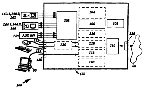
Figure 1 is a high-level. block diagram of.a multimedia collaboration device
100 constructed in accordance with the present invention. The multimedia
I o collaboration device 100 comprises a preamplifier and buffer unit 102; an
audio signal
conditioning unit 104; a switching unit 106; an Unshielded Twisted Pair (LTTP)
transceiver 108; a pair splitter 110; a routing unit 112; an encoding/decoding
unit 116;
a processor set 118; a memory 120; an input device interface 130; a companion
computer port 136; and a building or premises network port 138.
15 The premises network port 138 facilitates coupling to premises- or building-
based UTP wiring that forms a portion of a multimedia network 60. In one
embodiment, the premises network port 138 comprises a conventional network
coupling, such as an RJ-45 connector. The companion computer port 136
facilitates
coupling to one or more host or companion computers S0, such that the present
2o invention can offload real-time multimedia processing tasks from a
companion
computer SO and/or provide a pass-through for data packet exchange between a
host
computer 50 and the multimedia network 60. In one embodiment, the companion
computer port 136 comprises a conventional network coupling that is compatible
with
the premises network port 138. In another embodiment, the premises network
port
25 138 may employ a more sophisticated or modern protocol than that used by
the
companion computer port 136. In yet another embodiment, a host or companion
computer may access the multimedia collaboration device 100 via the premises
network port 138, and hence such an embodiment may not include a separate
companion computer port 136. It is also possible for the present invention to
communicate with a host or companion computer 50 over the data networking
ports
136, 138 for use in running Graphical User Interfaces (GUIs) or coordinating
with
application processes executing on the host or companion computer 50.
The preamplifier and buffer unit 102 receives AN signals from a left and a
right microphone 140.1, 140.2 and a camera 142, and transmits AN signals to a
left
-11-
CA 02318395 2000-07-10
i
WO 99/38324 PCT/US99/01789
and a right speaker 144.1, 144.2 and 2 display device 146. The preamplifier
and
buffer unit 102 can additionally send and receive A/V signals via a set of
auxiliary
(AtJ7~ A/V ports 148, which could couple to a device such as a Video Cassette
Recorder (VCR).
As elaborated upon below, the audio signal conditioning unit 104 provides
volume control functionality in conjunction with echo-canceled stereo
microphone or
mono synthetic aperture microphone capabilities. In one embodiment, the echo-
canceled stereo microphone and mono synthetic aperture microphone capabilities
may
be implemented in a single mode-controlled Digital Signal Processor (DSP)
chip, in a
1o manner that may facilitate user-selectivity between these two types of
microphone
functionality. If the microphone array 140. l, 140.2 includes more than two
microphones, it may be desirable to employ DSP techniques to synthesize a
stereo
synthetic aperture microphone. Further multiple microphone processing modes,
such
as stochastic noise suppression for extreme noise environments, can also be
included.
In the present invention, transfer of incoming and/or outgoing A/V signals
between a variety of sources and/or destinations is required, including the
microphones 140.1, 140.2, the camera 142, the speakers 144.1, 144.2, the
display
device 146, other AN or I/O devices, the premises network port 138, and/or the
companion computer port 136. Signal transfer pathways for such sources and
2o destinations may ultimately be analog or digital in nature. To meet these
switching
needs, the multimedia collaboration device employs the switching unit 106,
which
selectively routes analog AN signals associated with the microphones 140.1',
140.2,
the camera 142, the speakers 144.1, 144.2, the display device 146, and/or
other
devices to or from the analog AN UTP transceiver 108 and/or the
encodingldecoding
unit 116. The encodingldecoding unit 116 may also perform any required
conversion
between analog and digital formats.
As further described below, the analog A/V LTTP transceiver 108 provides an
analog signal interface to the pair splitter 110, which separates data
networking and
analog AN signals. In many cases this signal separation is most easily
accomplished
3o by selectively separating wires or wire pairs, but may also include the use
of passive
(or equivalent) wire switching arrangements and programmable Frequency
Division
Multiplexing (FDM) modulators and demodulators. As indicated earlier, the
encoding/decoding unit 116 performs conversions between analog and digital
signal
formats, and as such also compresses and decompresses AN signals. Although not
- 12-
,~ CA 02318395 2000-07-10
WO 99/38324 PCT/US99/01789
shown, those skilled in the art will understand that an ISDN transceiver,
inverse
multiplexes, network connector, Q.931 call control, etc...can be introduced
into the
architecture to add support for ISDN. The processor set 118 controls the
operation of
the multimedia collaboration device 100, and performs data network
communication
operations. In conjunction with operating system and other software resident
within
the memory 120, the processor set 118 may provide graphic overlay capabilities
on a
video image so as to implement any GLJI capabilities. These GUIs may
facilitate
control over the operations of the present invention, and may further provide
intemet
browsing capabilities, as described in detail below. The routing unit 112
performs
to network packet exchange operations between the premises network port 138,
the
companion computer port 136, and the processing unit 118, where such packets
may
include data, portions of, or entire digital AV streams, and/or network
configuration
or traffic monitoring information. Finally, the input device interface 130 may
provide
auxiliary mouse and keyboard ports 132, 134, and may also support an internal
local
geometric pointing input device as described below.
Particular groupings of the aforementioned elements may be packaged in
various manners so as to match particular deployment settings. For example,
selected
element groupings may reside within or upon a peripheral box package, computer-
bus-compatible card, or housing 150, where such element groupings may include
2o various A/V transducers. The nature of the selected package 150, and the
manner in
which the aforementioned elements are incorporated therein or thereupon as
integrated, modular, plug-in, and/or other types of components, is dependent
upon the
manner in which the present invention is employed, and may be subject to or
adaptive
to evolving market forces and embedded legacy equipment investments. Three
exemplary types of packages are described in detail hereafter.
Figure 2 is a high-level perspective view illustrating a box package 160 for
the
multimedia collaboration device 100. This illustrative box package 160
comprises a
housing I62 having a control panel 164 and a cable panel 182. The control
panel 164
includes an audio mode control 166; a microphone/speaker/ headset selector
168; a
$o microphone mute control 170; a holdlresume control I72; ALJX video and
audio
inputs 174,176; a telephone add/remove control 178; and a speaker/earphone
volume
control 180. The audio mode control 166 facilitates user-selection between
stereo
microphone and synthetic apern>re microphone operation, as further described
below.
The microphone/speaker/headset selector 168 provides for user-selection of
different
-I3-
CA 02318395 2000-07-10
WO 99/38324 PCT/US99/01789
audio input/output interfaces. and the microphone mute control 170 facilitates
user
control over audio input muting. The hold/resume control 172 pauses or resumes
audio inputs in response to user-selection. The AtTX video and audio inputs
174, I 76
respectively facilitate video and audio input from various sources. The
telephone
add/remove control 178 provides control of the insertion of an optional bridge
or
coupling to a telephone line for two-way audio contact with an addition of
third-party
telephone user. The supporting electrical couplings would provide for standard
telephone loop-through. . In one embodiment, the telephone addlremove control
178
includes conventional telephone line echo cancellation circuitry to remove the
o undesired transmit/receive coupling effects introduced by telephone loops.
Finally,
the speaker/earphone volume control 180 controls the amplitude of an audio
signal
delivered to speakers or an earphone (in accordance with the setting of the
microphone/speaker/headset selector 168). Some implementations may include
separate volume controls for speakers, earphones, and/or auxiliary audio UO.
15 The cable panel 182 on the box package 160 includes inputs and outputs that
facilitate coupling to a camera/microphone cable 184; a premises UTP cable
186; left
and right speaker cables 188, 190; a video monitor or video overlay card cable
192;
and a UTP computer networking cable 194.
The box package 160 is suitable for use with a companion desktop or portable
2o computer, and could reside, for example, underneath, atop, or adjacent to a
computer
or video monitor. Furthermore, a single box package 160 may be used to provide
a
plurality of companion computers 50 with multimedia collaboration
capabilities, for
example, in a small office environment.
Those skilled in the art will understand that the above combination of
features
25 is illustrative and can be readily altered. Those skilled in the art will
also understand
that in an alternate embodiment, the box package 160 could include a built-in
microphone or microphone array, as well as one or more speakers. Furthermore,
those skilled in the art will understand that one or more controls described
above
could be implemented via software.
3o Figure 3 is a suggestive high-level drawing showing the format of a plug-in
card package 200 for the multimedia collaboration device 100. The plug-in card
package 200 comprises a circuit board or card 202 having a standard interface
204
that facilitates insertion into an available slot within a computer. For
example, the
standard interface 204 could comprise plated connectors that form a male
Peripheral
-14-
CA 02318395 2000-07-10
WO 99/38324 PCT/US99/01789
Component Interface (PCI) connector, for insertion into a female PCI slot
coupled to
a PCI bus. The elements comprising the multimedia collaboration device 100 may
be
disposed upon the card 202 in the form of discrete circuitry, chips, chipsets,
and/or
multichip modules. The card 202 includes inputs and outputs for coupling to a
camera/microphone cable 214; left and right speaker cables 206, 208; a
premises UTP
cable 210; and a UTP-to-computer cable 212 that facilitates pass-through of
data
networking signals to an existing data networking card. It is understood that
conventional PCI bus interface electronics and firmware may be added to this .
.
configuration. Alternatively, the PCI bus may simply be used to provide power
and
~ o electrical reference grounding.
The multimedia collaboration device 100 may include more extensive data
networking capabilities, capable in fact of supporting essentially all the
networking
needs of one or more companion or host computers, as described in detail
below. In
this variation, the plug-in card package 200 may therefore be used to provide
a
15 computer into which it is inserted with complete data networking
capabilities in
addition to multimedia collaboration capabilities via transfer of data
networking
packets between the interface 204 and the computer, in which case the UTP-to-
computer cable 212 may not be necessary. The presence of the plug-in-card
package
200 may therefore obviate the need for a separate network interface card (NIC)
in
2o market situations in which sufficient evolution stability in data
networking
technologies exists.
The plug-in card package 200 may be used to provide older or less-capable
computers with comprehensive, up-to-date real-time multimedia collaboration
capabilities. Alternatively, the plug-in card package 200 can provide video
overlay
25 multimedia capabilities to computer systems having a monitor for which a
video
overlay card is unavailable or difficult to obtain. In the event that video
overlay
multimedia capabilities are to be delivered to a display or video monitor
other than
that utilized by the companion computer 50, the plug-in card package 200 may
include a port that facilitates coupling of a video monitor or video overlay
card cable
192 in a manner analogous to that shown in Figure 2. A host computer 50 that
incorporates a plurality of plug-in card packages 200 could be used as a
multimedia
collaboration server for other computers, in a manner understood by those
skilled in
the art.
- is -
CA 02318395 2000-07-10
WO 99/38324 PC'T/US99/01789
Those skilled in the art will ad3itionally understand that one or more of the
physical panel controls described above with reference to the box package 160
would
be implemented via software control for the plug-in card package 200.
Figure 4 is a perspective view of a stand-alone package 300 for the multimedia
collaboration device 100 that includes a range of advantageous internal A/V
transducer configurations. In one deployment, the stand-alone package may be
attached, mounted, or placed proximate to the side of a computer monitor or
laptop/palmtop computer, and hence is referred to herein as a "side-kick"
package
300.
1o The side-kick package 300 provides users with a self contained highly-
localized multimedia communication interface. The incorporation of the
microphone
array 304 into the side-kick package 300 assists in controlling the present
invention's
superior audio performance relative to adaptive echo-canceled stereo
microphone and
adaptive echo-canceled mono synthetic aperture microphone capabilities
described
15 below. The placement of the camera 306 in close proximity to the flat
display device
312 aids in maintaining good user eye contact with a displayed image, which in
turn
better simulates natural person-to-person interactions during
videoconferencing. The
eye contact can be further improved, and manufacturing further simplified, by
an
integrated camera/display device as described below with reference to Figure
16
2o through 25.
The side-kick package 300 can be used in conjunction with a companion
computer 50, or in a stand-alone manner. When used with a companion computer
S0,
the side-kick package 300 eliminates the need to consume companion computer
screen space with a video window. As a stand-alone device, the side-kick
package
25 300 can be used, for example, in office reception areas; public kiosks;
outside
doorways; or alongside special-purpose equipment for which explicatory,
possibly
interactive assistance may be useful, such as a photocopier.
Relative to Figure 2, like reference numbers designate like elements. The
side-kick package 300 comprises a housing 302 in which the multimedia
3o collaboration device 100 described above plus additional elements such as
an internal
shock-mounted microphone array 304; a camera 306 that may include auto-focus,
auto-iris, and/or electronic-zoom features; acoustically-isolated stereo
speakers 308; a
thumbstick mouse or similar type of geometric input device 310; and a flat
display
device 312 may reside. The side-kick package 300 may further include display
- 16-
CA 02318395 2000-07-10
WO 99/38324 PCT/US99/01789
brightness and contrast controls 314, 316, and/or one or more auxiliary audio
level
controls 180. Additionally, the side-kick package 300 may include a control
panel
having physical panel controls such as an audio mode control I66; a
microphone/speaker/headphone selector 168; a microphone mute control 170; a
hold/resume control I72; AIJX video and audio inputs 174, I76; and a telephone
.
add/remove control 178, which function in the manner previously described.
Those
skilled in the art will understand that the functions of one or more of the
physical
controls shown in Figure 4 could be implemented so as to be controlled
remotely via
software. In some arrangements, there might not be any physical controls, in
which
1o case control is facilitated by GLTis executing on one or more companion
computers
S0. Ideally, this embodiment may include both physical and remote software
controls
so that it can operate as a fully stand-alone device as well as a slave device
supporting
applications running on the companion computer 50.
The side-kick package 300 has ports for coupling to a premises UT'P cable 336
15 and an optional tTTP-to-computer cable 338. The side=kick package 300 may
also
include another connector set 334, which, for example, facilitates coupling to
a
headset, an auxiliary mouse, and/or an auxiliary keyboard. Figure 4
additionally
depicts an overlay window 340 upon the flat display device 312, which may be
realized via graphics overlay capabilities. The graphics overlay capabilities
can
2o implement menus or windows 340 that can provide a user with information
such as
text or graphics and which may be selectable via the input device 310,
creating
internal stand-alone GUI capabilities.
Relative to each package 160, 200, 300 described herein, use of the
multimedia collaboration device 100 with one or more companion computers 50 to
25 effect digital networked AN communication advantageously spares each
companion
computer 50 the immense computational and networking burdens associated with
transceiving and encoding/decoding A/V streams associated with AN capture and
presentation. The invention may also incorporate additional video graphics
features
in any of the packages 160, 200, 300 described above, such as telepointing
over live
video and/or video frame grab for transference to or from a companion or host
computer 50.
While Figure 1 provides a broad overview of the architecture of the present
invention, specific architectural details and various embodiments are
elaborated upon
hereafter, particularly with reference to Figures 5, 6, and 7.
_ 17-
CA 02318395 2000-07-10
y
WO 99/38324 PC'T/US99/01789
43 Architectural Details
Figure ~ is a block diagram of a first embodiment of a multimedia
collaboration device 10 constructed in accordance with the present invention,
and
which provides primary and auxiliary (AU3~ support for analog A/V, and further
provides support for networked digital streaming. With reference to Figure 1,
like
reference numbers designate like elements. The embodiment shown in Figure 5
supports analog A/V, and comprises the preamplifier and buffer unit 102; the
audio
signal conditioning unit 104; the AN switch 106; the analog AN UTP transceiver
to 108; the pair splitter 110; a first and a second digital transceiver 111,
135; the routing
unit 1 I2; a network interface unit 114; an analog-to-digital (AID) and
digital-to-
analog (D/A) converter 116a; an AN compression/ decompression (codec) unit
116b;
at least one, and possibly multiple, processors 118.1, 118.n; the memory 120;
the UO
interface 130; and the companion and premises network ports 136, 138. An
internal
~ 5 bus 115 couples the network interface unit 114, the AN codec 116b, each
processor
118.1, 1 IB.n, the memory 120, and the I/O interface 130. Each of the audio
signal
conditioning unit 104, the AN switch 106, the analog A/V UTP transceiver 108,
the
routing unit I 12, and the A/D - D/A converter 116a may also be coupled to the
internal bus 115, such that they may receive control signals from the
processors 118.1,
2o 118.n.
_ The preamplifier and buffer unit 102 is coupled to receive left and right
microphone signals from a left and right microphone 140.1, 140.2,
respectively; and a
camera signal from the camera 142. It is understood that additional
microphones
140.3...140.x and processing 118 and/or switching capabilities 106 may be
included
25 to enhance the synthetic aperture microphone capabilities described below.
The
preamplifier and buffer unit 102 may further receive AUX A/V input signals
from one
or more auxiliary AN input devices such as an exteraal VCR, camcorder, or
other
device. The preamplifier and buffer unit 102 respectively outputs left and
right
speaker signals to a left and a right speaker 144.1, 144.2; and a display
signal to the
3o display device 146. The preamplifier and buffer unit 102 may also deliver
AUX AlV
output signals to one or more auxiliary devices.
The audio signal conditioning unit 104 facilitates the adjustment of outgoing
audio signal volume in conjunction with providing adaptive echo cancelled
stereo
microphone or mono synthetic aperture microphone processing operations upon
audio
- t8 -
CA 02318395 2000-07-10
WO 99/38324 PCT/US99/01789
signals received from the preamplifier and buffer unit 102. Figure 8 is a
block
diagram of an adaptive echo-canceled stereo microphone unit 103 within the
audio
signal conditioning unit 104. The adaptive echo-canceled stereo microphone
unit 103
comprises a stereo echo canceler 310 and a stereo volume control unit 350.
The stereo echo canceler 310 comprises conventional monoaural echo
canceler subsystems that function in a straightforward manner readily apparent
to
those skilled in the art. This arrangement includes a left microphone/left
speaker
(LM/LS) adaptive acoustic echo filter model 312; a left microphone/right
speaker
(LM/RS) adaptive acoustic echo filter model 314; a right microphone/left
speaker
(RM/LS) adaptive acoustic echo filter model 316; and a right microphone/right
speaker (RM/RS) adaptive acoustic echo filter model 318. It will be readily
understood by those skilled in the art that linear superposition results in
stereo echo
canceling capabilities for stereo microphones and stereo speakers.
The stereo volume control unit 350 is coupled to a volume adjustment control
such as described above with reference to the various package embodiments 160,
200,
300 shown in Figures 2, 3, and 4, and is further coupled to receive the left
and right
speaker signals. The stereo volume control unit 350 is also coupled to each
model
312, 314, 316, 318 in order to maximize the utilization of DSP arithmetic and
dynamic range throughout the full range of speaker volume settings. It is
understood
2o that stereo balance controls can be implemented using the same stereo
volume control
elements operating in complimentary increments.
The LM/LS and LM/RS models 312, 314 are coupled to receive the left and
right speaker signals, respectively. Similarly, the RMILS and RM/RS models
316,
3I8 are respectively coupled to receive the left and right speaker signals
300. Each of
the LM/LS, LM/RS, RM/LS, and RM/RS models 312, 314, 316, 318 incorporates an
adaptive coefficient tapped delay line weighting element coupled to its
corresponding
microphone 140.1,140.2 and speaker 144.1, 144.2 in a conventional manner.
Additionally, the LM/LS and LM/RS models 312, 314 maintain conventional
couplings to the left microphone 140. i to facilitate initial acoustic
environment and
subsequent adaptive acoustic training operations. Similarly, the RM/LS and
RN1/RS
models 316, 318 maintain couplings to the right microphone 140.2 to facilitate
these
types of training operations.
The stereo echo canceler 310 additionally includes a first signal summer 320
coupled to outputs of the left microphone 140.1, the LM/LS model 312, and the
- 19-
CA 02318395 2000-07-10
WO 99/38324 PCT/US99/01789
LM/RS model 314; plus a second sign~:l summer 322 coupled to outputs of the
right
microphone 140.2, the RM/LS model 316, and the RM/RS model 318. The first
signal summer 320 delivers a left echo-canceled signal to the A/V switch 106,
and the
second signal summer 322 delivers a right echo-canceled signal to the A/V
switch
106, in a manner readily understood by those skilled in the art.
In one embodiment, the stereo echo canceler 310 and stereo volume control
unit 350 are implemented together via DSP hardware and software. Furthermore,
a
single DSP may be used to implement the stereo echo canceler 310, the stereo
volume
control unit 350, and the adaptive echo-canceled mono synthetic aperture
microphone
to unit 105, which is described below. In an exemplary embodiment, such a DSP
may
comprise a Texas Instruments TMS320C54x generation processor (Texas
Instruments
Incorporated, Dallas, T3~.
In the event that a user employs an earphone, headphone set, or ALJX audio
device in conjunction with the present invention, as described above with
reference to
~5 the box, card, and side-kick packages 160, 200, 300, the stereo echo
canceler 310 is
placed in a bypassed, inactive, or quiescent state and the DSP and stereo
volume
control unit 350 facilitate normalization and/or volume adjustment in a
conventional
manner as understood by those skilled in the art. Alternatively, separate
volume
control and/or normalization circuitry could be provided when stereo
microphones or
2o the stereo echo canceler 310 is not needed. These may be implemented in
various
ways with respect to the paths connecting to the A/V switch.
Figure 9 is a block diagram of an adaptive echo-canceled mono synthetic
aperture microphone unit 105 within the audio signal conditioning unit 104.
With
reference to Figure 8, like reference numbers designate like elements. The
adaptive
25 echo-canceled mono synthetic aperture microphone unit 105 comprises the
volume
control unit 350 plus a synthetic aperture microphone processing unit 330,
which may
include hardware and/or software. The synthetic aperture microphone processing
unit
330 comprises a synthetic aperture microphone unit 340 which may include
hardware
and/or software to implement synthetic apemire microphone processing
algorithms; a
3o synthetic microphone/left speaker (SM/LS) model 332; a synthetic
microphone/right
speaker (SM/RS) model 334; and a signal summing circuit 336, each coupled in
the
manner shown.
The synthetic aperture microphone unit 330 is coupled to receive the left and
right microphone signals, and additionally includes conventions! adaptive
coefficient
-20-
CA 02318395 2000-07-10
WO 99/38324 PCT/US99/01789
weighting and training couplings. Taken together, the synthetic aperture
microphone
unit 330, the left microphone 140.1, and the right microphone 140.2 (plus one
or more
additional microphones that may be present) form a mono-output synthetic
aperture
microphone. The synthetic aperture microphone unit 330 performs delay and/or
frequency dispersion operations upon the left and right microphone signals to
internally create or define an audio reception sensitivity distribution
pattern in a
manner readily understood by those skilled in the art. The audio reception
sensitivity
distribution pattern includes.one or more spatial regions referred to as "hot-
spots," as
well as a set of spatial regions referred to as "rejection regions."
Typically, a set of
one or more "hot-spots" includes a primary hot-spot of maximal audio reception
sensitivity that has a particular position or orientation relative to the
geometry of the
microphone array 140.1, 140.2. The rejection regions comprise spatial
positions in
which the synthetic aperture microphone has minimal audio reception
sensitivity.
Figure 10 is an illustration showing an exemplary localized primary hot-spot
10-3 and a surrounding rejection region 10-8. Within the primary hot-spot 10-
3, the
synthetic aperture microphone 10-2 can detect sound waves produced by a
speaker
10-1. The location of the primary hot-spot may be adjusted in accordance with
particular conditions in an acoustic environment. In one embodiment, the
position or
orientation of the primary hot-spot may be modified under software control.
This in
2o turn could facilitate user-directed hot-spot positioning for optimizing
audio
performance in different acoustic situations. Figure 1 I is an illustration
showing
exemplary primary hot-spot directivity, where the synthetic aperture
microphone 11-2
captures directionally-specific speech energy from a user 11-1 within a
primary hot-
spot 11-3 that is offset relative to that shown in Figure 10. A rejection
region 11-8
exists outside the primary hot-spot 11-3 in a conventional manner.
The synthetic aperture microphone can additionally reject reflected speech
energy that originated within the primary hot-spot and that approaches the
microphone array 140.1, 140.2 from angles beyond those that span the primary
hot-
spot. Figure 12 is an illustration showing exemplary reflected speech energy
3o rejection. The synthetic apertiue microphone 12-2 detects sound waves
produced by
a user 12-1 within a primary hot-spot 12-3. The synthetic aperture microphone
12-2
rejects sound waves 12-5,12-6 originating within the primary hot-spot 12-3 and
reflected from nearby surfaces because the reflected sound waves are likely to
travel
through one or more rejection regions i2-8 along their reflection path.
-21 -
CA 02318395 2000-07-10
;~'"1
WO 99/38324 PCT/US99/01789
The synthetic aperture microphone is further advantageous by virtue of good
ambient acoustical noise rejection performance. Figure 13 is an illustration
showing
exemplary ambient audio noise rejection, in which a synthetic aperture
microphone
13-2 rejects conversational noise 13-4 and various forms of outside or
environmental
noise 13-5, 13-6, 13-7. The noise and noise reflections traveling towards the
microphone array 140.1, 140.2 enter a rejection region 13-8 through various
directions, and hence are strongly attenuated via the synthetic aperture
microphone's
directional rejection behavior. This is in contrast to a user 13-1 within a
primary hot-
spot 13-3, who produces sound waves that the synthetic aperture microphone 13-
2
to readily detects with high sensitivity.
Referring also now to Figures ~ and 9, the synthetic aperture microphone unit
330 outputs a mono microphone signal having a magnitude that most directly
corresponds to the amount of audio energy present within the set of hot-spots,
and in
particular the primary hot-spot. The synthetic aperture microphone output
signal has
15 little contribution from audio energy entering from any rejection region
directions.
Those of ordinary skill in the art will understand that multiple microphones
can be
used to extract voice information from background noise that is in fact louder
than the
actual speech using adaptive cancellation techniques such as those described
by Boll
and Pulsipher in IEEE Transactions on Acoustics, Speech, and Signal
Processing,
2o Vol. ASSP-28, No. 6, December 1980. This could be incorporated as a third
operational mode for the audio DSP, for supporting extreme noise environments
as
might be found on public streets or repair depots, for example.
The volume control unit 350 is-coupled to the left and right speaker signals,
as
are the SM/LS and SM/RS models 332, 334. The signal summing circuit 336 is
25 coupled to the output of the synthetic aperture microphone unit 340, as
well as outputs
of the SM/LS and SM/RS models 332, 334, and delivers an echo-canceled mono
synthetic aperture microphone signal to the A/V switch 106.
In one embodiment, the adaptive echo-canceled synthetic aperture microphone
unit 105 comprises DSP hardware and/or software. The present invention can
thus
3o provide either adaptive echo-canceled stereo microphone or adaptive echo-
canceled
mono synthetic aperture microphone capabilities in response to user selection.
In an
exemplary embodiment, the adaptive echo-canceled synthetic aperture microphone
unit 105 is implemented in a DSP such as the Texas Instruments T'MS320C54x
processor referenced above. Those skilled in the art will recognize that a
single DSP
CA 02318395 2000-07-10
WO 99/38324 PCT/US99/01789
system can be configured to provide bo~h the adaptive echo-canceled stereo and
mono
synthetic aperture microphone capabilities described herein as distinct or
integrated
operating modes.
In the event that a user employs an earphone, headphone set, or AIJX audio
devices in conjunction with the present invention, the synthetic aperture
microphone
unit 330 is placed in a bypassed, inactive, or quiescent state and the DSP
and/or
volume control unit 350 facilitate conventional normalization and adjustment
of
output signal amplitude, ~in a manner understood by those skilled in the art.
Alternatively, separate normalization and/or volume control circuitry could be
t o provided to accommodate the aforementioned devices.
Referring again to Figure 5, the AN switch 106 comprises conventional
analog switching circuitry that is coupled to the preamplifier and buffer unit
102, the
audio signal conditioning unit 104, the analog AN UTP transceiver 108, and the
A/D
- D/A converters 1 I 6a. The AN switch 106 further maintains ~a coupling to
the
t 5 internal bus 115, thereby facilitating processor control over AN switch
operation.
The AN switch 106 routes incoming signals generated by the left and right
microphones 140.1, 140.2 (or larger microphone array), the camera 142, and/or
any
AUX AN input devices to the analog AN UTP transceiver 108 or the A/D - D/A
converters 116a under the direction of a control signal received via the
internal bus
20 115. Similarly, the AN switch 106 selects either the analog AN UTP
transceiver 108
or the A/D - D/A converters 116a as a source for outgoing signals directed to
the left
and right speakers 144.1, 144,2, the display device 146, and/or any AUX A/V
output
devices.
The analog AN UTP transceiver I08 comprises a conventional analog A/V
25 transceiver that provides a signal interface to a first set of UTP wires
that carry analog
AN signals and which couple the analog AN UTP transceiver 108 to the pair
splitter
1 I0. The pair splitter 110 is further coupled to the first digital
transceiver 111 via a
second set of UTP wires that carry digital AN signals. The analog A/V UTP
transceiver 108 may be reconftgurable, supporting a range of analog 4-pair, 2-
pair, or
3~D 1-pair signal transmission methodologies. The selection of any particular
signal
transmission methodology may be performed under processor control or by
physical
configuration switching. Similarly, distance compensation adjustments may be
performed under processor control or via physical switching, or alternatively
through
automatic compensation techniques in a manner understood by those skilled in
the art.
- 23 -
;~kf ~ i'
CA 02318395 2000-07-10
WO 99/38324 PCTNS99/01789
The first and second digital tra~aceivers 111, 135 provide conventional
digital
interfaces to UTP wiring, and are coupled to the routing unit 112 in the
manner
shown. The second digital transceiver 135 is further coupled to the companion
computer port 136. The first and second digital transceivers 111, 135 may be
implemented using portions of a standard NIC, as described below, or by other
means.
In addition to the aforementioned couplings, the routing unit 112 is coupled
to the
network interface unit 114. The routing unit 112 comprises conventional
network hub
or mini-hub circuitry. In one embodiment; the routing unit 112 performs hard-
wired
signal distribution and merge functions. In an alternate embodiment, the
routing unit
t o 112 performs data packet delivery path selection operations.
The network interface unit 114 comprises conventional network interface
circuitry, for exchanging data with the internal bus 115 and data packets with
either
the multimedia network 60 or a companion computer 50 via the premises and
companion computer network ports 138, 136 in accordance with a conventional
t 5 networking protocol. In one embodiment, the network interface unit 114 is
implemented as at least one standard NIC. The NIC may typically include built-
in
data packet address examination or screening capabilities, and hence simplify
the
routing unit's function to one of communications distribution and merge
functions in
such an embodiment. These distribution and merge functions serve to provide
2o simultaneous signal or packet exchange among each of the premises network
port
138, the NIC 114, and the companion computer port i36. One advantage of an
embodiment employing a standard NIC is that the NIC could be easily replaced
or
upgraded to accommodate technological evolution. This range of possibilities
is
finther enhanced by the switching arrangement described below with reference
to
25 Figure 1 S. Although not shown, it is again understood that should ISDN
support be
deemed valuable, network connectors, interface electronics, inverse
multiplexers, and
Q.931 call control can be introduced through, for example, connection to the
internal
bus 115 in a manner familiar to those skilled in the art.
Taken together, the premises network port 138, the pair splitter 110, the
3o analog A/V UTP transceiver 108, the digital transceiver 111, the routing
unit 112, the
network interface unit 114, and the companion computer port 136 form 1 ) a
first
multimedia network interface for handling analog A/V signals; and 2) a second
multimedia network interface for handling digital A/V and data networking
signals.
Figure 14 is a block diagram of a first embodiment of a first 400 and a second
410
-24-
CA 02318395 2000-07-10
WO 99/38324 PCT/US99/01789
multimedia network interface provides by the present invention. The first
multimedia
network interface 400 comprises the aforementioned first set of UTP wires plus
the
analog AN UTP transceiver 108. The first multimedia network interface 400
facilitates the exchange of analog AN signals between the premises network
port 138
s and the analog AN UTP transceiver 108. The second multimedia network
interface
410 comprises the second set of UTP wires, the digital transceiver 111, the
routing
unit 112, and the network interface unit 114, which are coupled in the manner
shown.
In some implementations, the digital transceiver 135 may also be a T1IC that
may be
either similar to or different from a T1IC employed in the network interface
unit 114.
1 o The second multimedia interface 410 facilitates the exchange of digital
A/V and data
networking signals between the premises network port 138, the network
interface unit
114, and the companion computer port 136.
Figure 15 is a block diagram of a second embodiment of first and second
multimedia network interfaces provided by the present invention. The first and
1 s second multimedia network interfaces are implemented via a passive
switching
arrangement and/or an active analog switching matrix 420 that includes low-
capacity,
high-frequency analog protection devices. Such protection devices may comprise
three-terminal, back-to-back diode arrangements, as employed in a Motorola
BAV99LT1 (Motorola, Inc., Schaumberg, IL). In this arrangement, the analog
2o transceiver 108 may support a number of 4, 2, and 1 pair formats, which may
be
dictated by the marketplace. Alternatively, the analog transceiver 108 can be
a
replaceable module.
In the event that data networking is implemented via Gigibit Ethernet or other
network protocol that conventionally consumes the entire physical capacity of
an
2s entire RJ-45 connector, the present invention may employ an additional RJ-
45 or
other type of connector for carrying analog AN signals.
Via the second multimedia network interface, the present invention provides
internal data communication transmit, receive, and routing capabilities. An
external
or companion computer 50 can therefore issue control signals directed to the
present
3o invention in accordance with standard data networking protocols. The second
multimedia network interface can also provide "loop-through" signal routing
between
the premises network port 138 and the companion computer port 136.
Additionally,
the data routing capabilities provided by the second multimedia network
interface
facilitate coupling to both existing broadcast or switching hubs. The second
-25-
CA 02318395 2000-07-10
. )
WO 99/38324 PC'T/US99/01789
multimedia network interface also supports the transfer of digital A/V
streams. Thus,
the second multimedia network interface cleanly separates data communications
directed to one or more companion computers 50, the multimedia network 60, and
the
multimedia collaboration device 10.
Once again referring to Figure ~, each of the A/V switch 106, the analog A/V
UTP transceiver 108, the routing unit 112, the network interface unit 114, the
A/V
codec I 16b, the set of processors 118.1, 118.n, the memory 120, and the I/O
interface
130 is coupled to the internal bus 115. The A/V codec 116b is further coupled
to the
A/D - D/A converters 116a, which are coupled to the A/V switch 106. It is
noted that
~ o the A/D - D/A converters 116a may include color-space conversion
capabilities to
transform between RGB and YUV or other advantageous color spaces.
The memory 120 comprises Random Access Memory (RAM) and Read-Only
Memory (ROM), and stores operating system and application software 122, 124.
Depending upon the nature of the processors 118.1, 118.n, the operating system
122
could comprise a scaled-down, conventional, or enhanced version of
commercially-
available operating system software, and/or special-purpose software. In an
exemplary embodiment, the operating system I22 comprises Windows CE (Microsoft
Corporation, Redmond, WA) or another commercial product selected in accordance
with the particular environment in which the present invention is employed.
The
2o application software 124 may comprise programs for performing
videoconferencing,
messaging, publishing, broadcast reception, and media-on-demand operations,
and
intemet browsing using programs such as Netscape Navigator (Netscape
'Communications Corporation, Mountain View, CA). Depending upon the nature of
the processors 118.1, 118.n, the Internet browser program could be. a scaled
down,
conventional, or augmented version of a commercially-available browser.
The processors 118.1, 118.n manage communication with the network
interface unit 114, and control the overall operation of the multimedia
collaboration
device 10 in accordance with control signals received via the network
interface unit
114. The processors 118.1, I 18.n additionally provide graphics overlay
capabilities,
3o and may further provide Internet browsing capabilities in conjunction with
application
software 124 as previously described. Relative to managing communication with
the
network interface unit 114, the processors 1 I8.1, 118.n may manage protocol
stacks
and/or state machines. With regard to controlling the overall operation of the
multimedia collaboration device 10, the processors 118.1, 118.n issue control
signals
-26-
CA 02318395 2000-07-10
-'"'~ ,
WO 99/38324 PCT/US99/01789
to the AN switch 106 and execute application software resident within the
memory
120. The graphics overlay capabilities facilitate the placement of fonts,
cursors,
and/or graphics over video present upon the display device 146. With
sufficient
processing power, the present invention can serve as a stand-alone, real-time
video-
capable Internet appliance.
As described above, the A/D - D/A converters 116a may comprise
conventional circuitry to perform color-space conversion operations in
addition to
analog-to-digital and digital-to-analog signal conversion. The A/V codec 116b
comprises conventional A/V signal encoding and decoding circuitry, and
provides the
to present invention with compression and decompression capabilities. Together
these
enable the present invention to encode and decode A/V streams without loading
down
a companion computer's processing and networking power. Either of the first or
second multimedia network interfaces described above can route digital A/V
signals
to the A/V codec 116b, while routing non-A/V signals to the companion computer
50.
15 The present invention's ability to encode and decode A/V signals
independent of a
companion or external computer is particularly advantageous in situations in
which
video signal encoding and decoding must occur simultaneously, such as in 2-way
teleconferencing or network-based video editing applications. The present
invention
may support network-based video editing applications based upon a high
bandwidth
2o near-zero-latency compression approach, which can be implemented, for
example,
through JPEG or wavelet compression operations; or an interim compression
approach.
In one embodiment, the AN codec 116b comprises a chip or chipset. In
another embodiment, the A/V codec 116b comprises a processor 118.k capable of
25 performing compression and decompression operations. In more advanced
implementations, the A/V codec 116b could comprise a single processor 118.m
capable of performing user interface functions in addition to A/V compression
and
decompression operations. Such an implementation could also provide an
Application Program Interface (API) in conjunction with operating system
software
30 122. In an exemplary embodiment of such an implementation, the A/V codec
116b
may comprise a NUON processor (VM Labs, Mountain View, CA).
-27-
CA 02318395 2000-07-10
WO 99/38324 PCT/US99/01789
4.4 Additional Embodiments
Figure 6 is a block diagram of a second embodiment of a multimedia
collaboration device 20, which provides primary support for analog audio I/O
and
digital visual I/O, and further supports analog and digital auxiliary AN I/O,
plus
networked digital streaming. Relative to Figure 5, like reference numbers
designate
like elements.
The second embodiment of the multimedia collaboration device 20 includes a
digital camera 152, a digital display device 154, a digital AUX A/V interface
156, and
a stream selector 158. The digital camera 152 and the digital display device
154
1o respectively capture and display images in a conventional manner. The
digital AUX
AN interface 156 facilitates bidirectional coupling to auxiliary digital A/V
devices,
such as an external computer, a digital VCR, or Digital Versatile Disk (DVD)
player.
Each of the digital camera 152, the digital display device 154, and the
digital AUX
A/V interface 156 is coupled to the stream selector 158, which is coupled to
the A/V
15 codec 116b.
The stream selector 158 comprises conventional circuitry that selectively
routes digital streams between the AN codec I 16b and the digital camera 152,
the
digital display device 154, and the digital AUX AN interface 156. The stream
selector i 58 may route incoming digital image streams received from either of
the
2o digital camera 152 or the digital AUX AN interface 156 to the A/V codec
116b. In
one embodiment, the stream selector 158 may be capable of multiplexing between
these two incoming digital stream sources. Undersampling may also be used to
facilitate the compositing of multiple video images. Relative to outgoing
digital
image streams, the stream selector 158 may route such streams to either or
both of the
25 digital display device 154 and digital AUX AN interface 156, where such
routing
may occur in a simultaneous or multiplexed manner. The stream selector 158
additionally facilitates the exchange of digital audio streams between the A/V
codec
I 16b and the digital AUX AN interface 156.
The AN codec 116b and the A/D - D/A converters 116a together facilitate the
3o conversion of digital AN signals associated with the digital camera 152,
the digital
display device 154, and/or auxiliary digital AN devices into analog A/V
signals. The
A/V switch 106 facilitates exchange of these analog AN signals with AUX AN
devices and/or the premises network port 138.
-28-
CA 02318395 2000-07-10
WO 99/38324 PCT/US99/01789
Because the AN codec 116b is also coupled to the internal bus 1 I S and hence
to the network interface unit 114, digital AN signals captured from the
digital camera
I52 or directed to the digital display 154 or received from the digital AUX AN
interface 156 may be packetized and exchanged via the premises network port
138
and/or the companion computer port 136.
Figure 7 is a block diagram of a third embodiment of a multimedia
collaboration device 30, which provides primary support for analog audio I/O
and
digital visual I/O, support for digital auxiliary A/V I/O, and support for
networked i
digital streaming. Relative to Figures 5 and 6, like reference numbers
designate like
o elements.
The third embodiment of the multimedia collaboration device 30 includes a
digital camera 152, a digital display device 154, a digital AtJX A/V interface
156, and
a stream selector i58 in the manner described above. Analog audio signals
associated
with the microphones 140.1, 140.2 and speakers 144.1, 144.2 are muted through
the
15 A/D - D/A converters 116a and AN codec unit 116b. Thus, the third
embodiment of
the present invention manages digital AN streams, and may exchange such
streams
with the multimedia network 60 and/or a companion computer 50. T'he third
embodiment of the multimedia collaboration device 30 does not transmit analog
AN
signals over the multimedia network 60, and hence the analog switching unit
106, the
2o analog AN LJTP transceiver 108, and the pair sputter 110 described above
relative to
the first and second multimedia collaboration device embodiments are not
required.
4.5 Camera and Display Device Integration
As previously indicated, placement of the camera 142 in close proximity to the
25 display device 146 aids in maintaining good user eye-contact with a
displayed image,
thereby closely approximating natural face-to-face communication in
videoconferencing situations. Essentially perfect eye-contact can be achieved
by
integrating a largo-area photosensor array with a large-area array of emissive
or
transmissive devices that form the basis for display device pixels.
3o Multiple photosensor and display element integration techniques exist. In
general, the formation of an image using a photosensor array necessitates the
use of
optical elements in conjunction with photosensor elements. Photosensor and
display
element integration techniques are described in detail hereafter, followed by
image
formation considerations relative to integrated photosensor/display element
arrays.
-29-
a:.
CA 02318395 2000-07-10
WO 99/38324 PCT/US99/01789
4.6 Display Pizel and Photosensor Element Interieaving
One way of integrating photosensor elements with emissive or transmissive
display elements is via element interleaving. Figure 16 is an illustration
showing a
first photosensor and display element interleaving technique, in which display
elements 510 and photosensor elements 520 populate a viewing screen 502 in an
alternating manner. Each display element 510 generates or transmits light
corresponding to a particular color or set of colors. Similarly, each
photosensor
element 520 detects light corresponding to a particular color. As described in
detail
1o below, display elements 510 and photosensor elements 520 operate in a
temporally
and/or spatially separated manner relative to each other to ensure that image
capture is
essentially unaffected by image display.
Display and photosensor elements 510, 520 corresponding to a particular color
are interleaved in accordance with a color distribution scheme. Figure I7 is
an
t 5 illustration of an exemplary photosensor element color and display element
color
distribution scheme. In Figure 17, display elements 510 corresponding to the
colors
red, green, and blue are identified via the uppercase letters R, G, and B,
respectively.
Photosensor elements 520 corresponding to red, green, and blue are
respectively
identified by the lowercase letters r, g, and b. Display elements 510
corresponding to
2o a particular color are offset relative to each other, and interleaved with
display and
photosensor elements 510, 520 corresponding to other colors. Similarly,
photosensor
elements 520 corresponding to a particular color are offset relative to each
other, and
interleaved with display and photosensor elements 510, 520 corresponding to
other
colors. Those skilled in the art will recognize that a variety of photosensor
and
25 display element color distribution schemes are possible.
The presence of photosensor elements 520 interleaved with display elements
S 10 reduces image resolution, and increases pixel pitch (i.e., the spacing
between
pixels). To miniazize the effect that the photosensor elements 520 have upon
the
appearance of a displayed image, photosensor elements 520 having or consuming
a
3o smaller area than the display elements S 10 are employed. Furthermore,
various
display and photosensor element layout geometries may be used to produce an
interleaving pattern that closely approximates display element pitch found in
conventional display devices. Figure 18 is an illustration of a second
photosensor and
display element interleaving technique, in which photosensor and display
element
-30-
CA 02318395 2000-07-10
~i
WO 99/38324 PCT/US99/01789
geometries and size differentials aid in minimizing pixel pitch and maximizing
displayed image resolution. Since a viewer's eye will integrate or average the
light
output by groups of display elements S 10, interleaving techniques of the type
shown
in Figure 18 ensure that the viewer will perceive a high-quality image. Those
skilled
in the art will understand that various microoptic structures or elements,
such as
microlenses, could be employed in the noniuminent spaces between display
elements
510 and/or photosensor elements 520 to reduce or minimize a viewer's
perception of
nonluminent areas in a displayed image. Such microoptic structures are
elaborated
upon below.
1 o The display elements 510 referred to herein may comprise essentially any
type
of conventional light emitting or transmitting device, such as a Light
Emitting Diode
(LED) or Liquid Crystal Display (LCD) pixel element. Similarly, the
photosensor
elements 520 may comprise essentially any type of conventional light sensing
or
detecting device. For example, the photosensor elements 520 could comprise
15 photodiodes, such as Schottky or p-i-n photodiodes; phototransistors;
capacitive or
charge-coupled devices (CCDs); charge modulated devices (CMDs); or other types
of
light-sensitive devices. The photosensor elements 520 could be fabricated, for
example, using standard semiconductor processing techniques employed during
the
manufacture of flat panel displays.
2o In a typical display device, a single display element 510 is used to output
light
of a particular color. Display elements 510 based upon organic
electroluminescence
are capable of simultaneously generating light comprising multiple wavelengths
in the
visible spectrum, and form the basis for full-color LED arrays. In particular,
a single
Stacked Organic Light Emitting Diode (SOLED) pixel element can produce red,
25 green, and blue light. The intensity of each color is independently
tunable, as is each
color's mean wavelength. Thus, a single SOLED can form a full-color pixel. As
an
alternative to organic electroluminescent materials, the present invention may
employ
other full-color transparent or semitransparent luminescent materials, such as
light-
emitting and/or light-responsive polymer filins.
3o Figure 19 is a cross-sectional view showing a full-color pixel array
integrated
with a photosensor element array upon a common substrate 702 such as glass or
plastic. As an example, a SOLED 710 is considered as the full-color pixel
technology
in the discussion that follows. Those skilled in the art will understand that
the
concepts described herein can be applied to other full-color pixel
technologies. Each
3;
CA 02318395 2000-07-10
WO 99/38324 PCT/US99/01789
SOLED 710 comprises a first, second, and third semitransparent electrode 712,
714,
716; a first, second, and third organic electroluminescent layer 722, 724,
726; and a
reflecting contact layer 730, in a manner understood by those skilled in the
art. Each
electroluminescent layer 722, 724, 726 emits light in a particular wavelength
range in
response to an applied electric field. For example, the first, second, and
third organic
electroluminescent layers 722, 724, 726 could respectively output blue, green,
and red
light.
A color filter 750, an optional microoptic structure 760, and a photosensor
element 520 form a color-specific photosensor element 770 that is fabricated
adjacent
1o to each SOLED 710. The microoptic 760 may comprise one or more microlenses,
apertures, and/or other types of planar optic structures, and serves to focus
incoming
light onto the photosensor element 520 to aid image formation in the manner
described below. The microoptic structure 760 may be formed through the
application of conventional microlens or planar optic fabrication techniques
during
15 photosensor element fabrication steps. For example, the microoptic
structure 760
may be formed by depositing a selectively-doped dielectric or dielectric stack
prior to
or during photosensor element fabrication, in a manner well understood by
those
skilled in the art.
The color-specific photosensor element 770 may also include one or more
20 antireflection layers, which are deposited in a conventional manner.
Additionally, one
or more types of passivation or isolation materials, such as Silicon Dioxide,
Silicon
Nitride, Polyicoide, or spin-on-glass may be deposited in between each SOLED
710
and color-specific photosensor element 770 in a manner understood by those
skilled
in the art.
25 Each color-specific photosensor element 770 detects light characterized by
a
specific wavelength interval. Thus, while any given SOLED 710 may
simultaneously
output red, green, and/or blue light, separate color-specific photosensor
elements 770
are used to individually detect red, green, and blue light. Because each SOLED
710
forms a full-color pixel, integration of a SOLED array with a photosensor
array in the
3o manner shown in Figure 19 is particularly advantageous relative to
providing a high-
resolution display having image capture capabilities.
4.7 Display and Photosensor Element Stacking
a) Integrated SOLEDlPhotosensor Element
-32-
CA 02318395 2000-07-10
WO 99!38324 PCT/US99/01789
A full-color pixel element such as a SOLED 710 and a color-specific
photosensor element 770 can be integrated together, such that the
incorporation of a
photosensor element array into a display element array can be accomplished
essentially without a resolution or pixel pitch penalty. Figure 20 is a cross-
sectional
view showing an integrated full-color pixeUphotosensor element 800, which may
form the basis of an integrated display element/photosensor element array. For
purpose of example, the full-color pixel element is considered to be a SOLED
810 in
the description that follows. Those skilled in the art will understand that
other types
of full-color pixel technologies could be used to pmduce the integrated full-
color
to pixeUphotosensor element 800 described hereafter.
Relative to Figure 19, like reference numbers designate like elements. The
full-color pixel/photosensor element 800 comprises a SOLED 810 having a color-
specific photosensor element 770 fabricated thereupon. The full-color pixeU
photosensor element 800 is fabricated upon a substrate 702 such as glass. The
15 SOLED 810 comprises a first, a second, a third, and a fourth
semitransparent
electrode 712, 714, 716, 812; a first, second, and third organic
electroluminescent
layer 722, 724, 726; and a patterned reflecting contact layer 830.
With the exception of the fourth semitransparent electrode 812 and the
patterned reflecting contact layer 830, the SOLED 810 shown in Figure 20 is
2o essentially the same as that depicted in Figure 19. The fourth
semitransparent
electrode 812 serves as one of the electrodes for the photosensor element 520
within
the color-specific photosensor element 770, in a manner readily understood by
those
skilled in the art. Deposition of the fourth semitransparent electrode 812 may
not be
required under the patterned reflecting contact layer 830, and as such the
SOLED 810
25 and color-specific photosensor element 770 may not share a common
electrical
interface layer. The patterned reflecting contact layer 830 comprises
conventional
contact materials or metals that have been patterned to include a gap or
opening.
The color-specific photosensor element 770 is fabricated on top of the fourth
semitransparent electrode 812, in the opening defined in the patterned
reflecting
contact layer 830. The color-specific photosensor element 770 thus detects
light that
has been transmitted through the substrate 702 and each of the first through
fourth
semitransparent electrodes 712, 714, 716, 812. Those skilled in the art will
understand that the location of the opening defined in the patterned
reflecting contact
layer 830, and hence the location of the color-specific photosensor element
770 upon
-33-
CA 02318395 2000-07-10
WO 99/38324 PCT/US99/01789
the SOLED 810, may vary among adjacent full-color pixel/photosensor elements
to
ensure that the a human observer perceives a high-quality displayed image. The
SOLED 810 and the color-specific photosensor element 770 may operate in a
temporally-separated manner to ensure that image capture is essentially
unaffected by
image display, as further elaborated upon below.
b) Stacked Full-Color EmitterlFull-Color Detector Structures
A firll-color pixel element, such as a stacked organic electroluminescent
(SOE) structure, may also be used to detect light. Thus, a single structure
based upon
to full-color materials technology may be used for both RGB light emission and
RGB
light detection, thereby advantageously facilitating the integration of a
photosensor
element array and a display element array while maintaining small pixel pitch
and
high image resolution.
Figure 21 is a cross-sectional view of a first full-color emitterldetector
900. In
15 the description that follows, the first full-color emitter/detector 900 is
considered to be
an SOE-based device. Those skilled in the art will recognize that other fill-
color
technologies could be employed to produce the first fill-color
emitter/detector 900 in
alternate embodiments.
Relative to Figures 19 and 20, like reference numbers designate like elements.
2o The first fi111-color emitter/detector 900 is fabricated upon a substrate
702 such as
glass; and comprises first through seventh semitransparent electrodes 712,
714, 716,
812, 912, 914, 916; first through sixth organic electroluminscent layers 722,
724, 726,
922, 924, 926; an optional microoptic structure 920; and a reflecting contact
layer
730.
25 In the first fiill-color emitter/detector 900, the first through third
organic
electroluminescent layers 722, 724, 726 serve as RGB light emitters controlled
by
voltages applied to the first through fourth semitransparent electrodes 712,
714, 716,
812, and thus form a SOLED 902. The microoptic structure 920 comprises one or
more microlenses, apertures, and/or other planar microoptic structures that
focus
3o incoming light into the fourth, fifth, and sixth organic electroluminescent
layers 922,
924, 926, which in turn produces or induces pairwise voltage differences
across the
fifth, sixth, and seventh semitransparent electrodes 912, 914, 916 aad the
reflecting
contact layer 730. The microoptic structure 920, the fourth through sixth
organic
electro-luminescent layers 922, 924, 926, the fifth through seventh
semitransparent
CA 02318395 2000-07-10
WO 99/38324 PC'TNS99/01789
electrodes 912, 9I4, 916, and the reflecting contact layer 730 therefore form
a first
SOE photosensor 904 for detecting RGB light.
Light emitted by the SOLED 902 may travel through the substrate 702 toward
a viewer, or through the first SOE photosensor 904, where it is reflected back
toward
the substrate 702 by the reflecting contact layer 730. The first SOE
photosensor 904
detects incoming Iight that has traveled through the substrate 702 and the
SOLED
902. As described in detail below, SOLED light emission and SOE photosensor
light
detection may occur in a temporally and/or spatially separated manner, such
that
image capture is essentially unaffected by image display.
1 o Those skilled in the art will recognize that the SOLED 902 and the first
SOE
photosensor 904 may be able to share a single semitransparent electrode at
their
interface in an alternate embodiment (i.e., the first full-color
emitterldetector 900 may
be fabricated without one of the fourth or fifth semitransparent electrodes
812, 912)
since SOLED and SOE photosensor operation within a single first full-color
1 s emitter/detector 900 may be temporally separated). Those skilled in the
art will also
understand that in addition to the layers described above, the first fill-
color
emitter/detector 900 may include additional micmoptic layers and/or one or
more
antireflective layers. Those skilled in the art will further recognize that in
an alternate
embodiment, the first full-color emitter/detector 900 could be fabricated such
that the
2o first SOE photosensor 904 resides in contact with the substrate 702, and
the SOLED
902 resides on top of the first SOE photosensor 904. In such an embodiment,
the
reflecting contact layer 730 would be incorporated into the SOLED 902. Those
skilled in the art will also recognize that either or both of the SOLED 902
and the first
SOE photosensor 904 could be implemented using other types of transparent or
25 semitransparent full-color device and/or materials technologies in
alternate
embodiments.
Figure 22 is a cross-sectional view of a second full-color emitter/detector
1000. For ease of understanding, the second full-color emitter/detector is
considered
to be based upon SOE technology in the following description. Those skilled in
the
3o art will recognize that other full-color materials technologies could be
employed to
produce the second full-color emitter/detector 1000 in alternate embodiments.
Relative to Figure 20, like reference numbers designate like elements. The
second full-color emitter/detector 1000 is fabricated upon a substrate 702
such as
glass, and comprises a first through fifth semitransparent electrode 712, 714,
716,
-35-
CA 02318395 2000-07-10
WO 99/38324 PC'T/US99/01789
812,1 O 12; a first through sixth organic electroluminescent layer 722, 724,
726, 1022,
1024, 1026; an optional microoptic structure 1020; a first, a second, and a
third
reflecting contact layer 1032, 1034, 1036; and a first and a second boundary
structure
1042, 1044.
s The first through third organic electroluminescent layers 722, 724, 726, in
conjunction with the first through fourth semitransparent electrodes 712, 714,
716,
812, form a SOLED 902 in a manner analogous to that described above with
reference to Figure 21. -The microoptic structure 1020, the first through
third organic
electroluminescent layers 1022, 1024, 1026, the reflecting contact layers
1032, 1034,
to 1036, and the first and second boundary structures 1042, 1044 form a second
SOE
photosensor1004.
Taken together, the fourth, fifth, and sixth organic electroluminescent layers
1022, 1024, 1026 and the boundary structures 1042, 1042 span an area
essentially
equal to that of any semitransparent electrode 712, 714, 716, 812, 1012. The
first
1 s boundary structure I 042 separates the fourth and fifth organic
electroluminescent
layers 1022, 1024. Similarly, the second boundary structure 1044 separates the
fiRh
and sixth organic electroluminescent layers 1024, 1026. The first, second, and
third
reflecting contact layers 1032, 1034, 1036 respectively reside upon or atop
the fourth,
fifth, and sixth organic electroluminescent layers 1022, 1024, 1026.
2o The microoptic structure 1020 may comprise one or more microlenses,
apertures, and/or other planar microoptic structures that focus incoming light
into the
fourth, fiRh, and sixth organic electroluminescent layers 1022, 1024, 1026.
The
fourth organic electroluminescent layer 1022 detects incoming photons having a
wavelength range associated with a particular color, for example, red. The
presence
25 of such photons in the fourth organic electroluminescent layer produces or
induces a
voltage difference between the fourth semitransparent electrode 1012 and the
first
reflecting contact layer 1032. Similarly, the fifth and sixth organic
electroluminescent
layers 1024, 1026 each detect incoming light corresponding to a particular
wavelength
range, for example, green and blue, respectively. The presence of blue and
green light
3o respectively induces a voltage difference between the second and third
reflecting
contact layers 1034, 1036 and the fourth semitransparent electrode 1012.
Those skilled in the art will recognize that the thickness of each of the
fourth,
fifth, and sixth organic electroluminescent layers 1022, 1024, 1026 may be
varied in
accordance with the particular wavelength range that each such layer is to
detect.
-36-
CA 02318395 2000-07-10
i
WO 99/38324 PCT/US99/01789
Those skilled in the art will additional:y recognize that the microoptic
structure 1020
may be fabricated such that its characteristics vary laterally from one
organic
electroluminescent layer 1022, 1024, 1026 to another, and that one or more
antireflection layers may be incorporated into the second full-color
emitter/detector
1000. Moreover, the SOLED 902 and the second SOE photosensor 1004 may be able
to share a single semitransparent electrode at their interface a manner
analogous to
that described above relative to the first SOE photosensor 904. Finally, those
skilled
in the art will recognize that either or both of the SOLED 902 aad the second
SOE
photosensor 1004 could be implemented using other types of transparent or
1o semitransparent full-color technologies in alternate embodiments.
4.8 Other Integrated Emitter/Detector Structures
As indicated above, a light detecting element may be sinular, nearly, or
essentially identical in structure and/or composition to a light emitting
element.
15 Because any given emitter/detector structure may be used for light emission
during
one time interval and light detection during another time interval as
described below,
a single light emitting structure may also be used for light detection.
Figure 23 is a cross-sectional diagram of a third full-color emitter/detector
1100. For ease of understanding, the third full-color emitter/detector is
described
2o hereafter in the context of SOE technology. 'Those skilled in the art will
understand
that other full-color materials and/or technologies could be employed to
produce the
third full-color emitter/detector 1100 in alternate embodiments.
Relative to Figure 19, like reference numbers designate like elements. The
third full-color emitter/detector 1100 is fabricated upon a substrate 702 such
as glass
25 or plastic. The third full-color emitterldetector 1100 comprises a SOLED
710 having
a first through a third semitransparent electrode 712, 714, 716; a first, a
second, and a
third organic electroluminescent layer 722, 724, 726; a reflecting top contact
layer
730. The third full-color emitter/detector 1000 may additionally include a
microoptic
layer 1120. During a first time interval, the SOLED 710 may operate in a light
'0 emitting mode in a conventional manner. During a second time interval, the
SOLED
710, in conjunction with the microoptic layer 1120, operates as a photosensor
to
detect incoming light in a manner analogous to that described above relative
to the
SOE photosensors 904.
-37-
CA 02318395 2000-07-10
WO 99/38324 PCT/US99/01789
The microoptic layer 1120 may comprise a microlens and/or other type of
planar optic structure, and may be fabricated such that different portions of
the
microoptic layer 1120 affect Iight in different manners. This in turn could
aid in
providing particular light detection responsivity while minimally affecting
the manner
in which light emitted by the third full-color emitter detector 1100 will be
perceived
by a human eye.
Figure 24 is a top-view of an exemplary microoptic layer 1120 having
different optical regions 1190, 1192 defined therein. A first optical region 1
i 90 may
allow light to pass in an essentially unaffected manner. A second optical
region 1192
1o serves as a focusing element that produces a desired spatial or modal light
intensity
pattern within the third full-color emitter/detector. As the second optical
region 1192
occupies a smaller area than the first optical region 1190, its affect upon
human
perception of light emitted by the third full-color emitter/detector may be
small or
minimal. Those skilled in the art will understand that the location of the
second
15 optical region 1192 may vary among adjacent third full-color
emitter/detectors 1100,
to further enhance the quality of a displayed image seen by a human eye.
In an alternate embodiment, the microoptic layer 1120 could include
additional optical regions. For example, one or more portions of the first
optical
region 1190 could be designed or fabricated to compensate for any effects the
second
20 optical region 1192 has upon human perception of light emitted by the third
full-color
emitter/detector 1100. As another example, the second optical region 1192
could be
replaced or augmented with other, possibly smaller, optical regions
distributed across
the plane of the microoptic layer 1120 to further optimize Iight detection and
emission
characteristics.
4.9 Image Formation
A simple or compound lens is conventionally used to focus an image onto an
array of photosensors. Figure 25 illustrates a simple or compound lens 600
that
receives or collects light 602 reflected or emanating from an object 604, and
focuses
3o such light onto a photosensor element array 606.
Relative to a single array that integrates both display and photosensor
elements S 10, 520, the use of a conventional simple or compound lens would
adversely affect the characteristics of the displayed image. To facilitate
image
detection in such an integrated array, photosensor elements 520 may
incorporate
-38-
CA 02318395 2000-07-10
v
WO 99/38324 PCT/US99/01789
microoptic structures and/or apertures, as described above, on an individual
basis.
Each aperture aadlor microoptic structure focuses light received from a small
portion
of an object onto a photosensor element 520. As depicted in Figure 25, sets of
microoptic-equipped photosensor elements 520 within a photosensor array 620
receive light 622, 624 emanating from different parts of an object 626. Those
skilled
in the art will recognize that the present invention could employ microoptic
structures
or elements that focus light onto multiple photosensor elements 520 in
alternate
embodiments, where such microoptic elements may be incorporated onto separates
substrates. Signals output by the microoptic-equipped photosensor elements 520
are
1o transferred to an image processing unit 628 for further processing, as
described in
detail below.
Conventional display devices comprise multiple rows or lines of display
elements 510, and produce a displayed image on a Iine-by-line basis.
Similarly,
conventional photosensor arrays comprise multiple rows of photosensor elements
520,
which may be scanned oa a line-by-line basis during image capture operations.
The
integrated display element/photosensor element arrays considered herein may
also 1 )
produce a displayed image by activating display elements S10 on a line-by-line
basis;
and 2) capture light received from an object by detecting photosensor element
output
signals on a line-by-line basis.
Ia one embodiment, the present invention includes a display control circuit
for
performing display Iine scans that produce a displayed image on a line-by-line
basis,
and a capture control circuit for performing photosensor line scans that read
photosensor element output signals on a line-by-line basis. Each of the
display and
capture control circuits include conventional clocking, address decoding,
multiplexing, and register circuitry. In order to ensure that image capture is
essentially unaffected by image display (i.e., to prevent light emitted or
transmitted by
display elements 510 from affecting incoming light detection by adjacent
photosensor
elements 520), the display line scans and photoscnsor line scans may be
temporally
and/or physically separated relative to each other. This separation may be
controlled
3o via conventional clocking and/or multiplexing circuitry.
In one embodiment, photosensor line scans are initiated after a display line
scan has generated fifty percent of an image (i.e., after fifty percent of the
display
- element lines have been activated during a single full-screen scan cycle),
such that the
photosensor line scan trails the display line scan by a number of display
element rows
-39-
;~:..~.. ._.~:_ :. !:
CA 02318395 2000-07-10
WO 99/38324 PCT/US99/01789
equal to one-half of the total number of display element rows present in the
integrated
display element/ photosensor element array. More generally, the capture line
scan
could trail the display line scan by a particular time interval or a given
number of
completed display line scans.
In another embodiment, one-half of the display element lines define a first
display field, and one-half of the display element lines define a second
display field,
in a manner well understood by those skilled in the art. Similarly, one-half
of the
photosensor element lines define a first photosensor field, and the remaining
photosensor element lines define a second photosensor field. The first display
field
to and either of the first or second photosensor fields may be scanned either
simultaneously or in a time-separated manner, after which the second display
field
and the remaining photosensor field may be scanned in an analogous manner.
Those
skilled in the art will recognize that the display and photosensor field
scanning can be
performed in a manner that supports odd and even field scanning as defined for
NTSC
15 and PAL television standards.
In yet another embodiment, a single full-screen display line scan cycle is
completed, after which a single full-screen photosensor line scan cycle is
completed,
after which subsequent fill-screen display line and photosensor line scans are
separately performed in a sequential manner.
2o The set of photosensor element output signals received during any given
photosensor line scan are transferred to an image processing unit 628. The
image
processing unit 628 comprises signal processing circuitry, such as a DSP, that
- performs conventional digital image processing operations such as two-
dimensional
overlap deconvolution, decimation, interpolation, and/or other operations upon
the
25 signals generated during each photosensor line scan. Those skilled in the
art will
understand that the number and types of digital image processing operations
performed upon the signals generated during each photosensor line scan may be
dependent upon the properties of any microoptic structures associated with
each
photosensor element 520. Those skilled in the art will further understand that
signal
3o conditioning circuitry may additionally be present to amplify photosensor
element
signals or eliminate noise associated therewith. Such signal conditioning
circuitry, or
a portion thereof, may be integrated with each photosensor element 520.
The image processing unit 628 forms a conventional final output image array
using signal processing methods, and outputs image array signals to a buffer
or
-40-
CA 02318395 2000-07-10
WO 99/38324 PCT/US99/01'789
memory, after which such signals may be compressed and incorporated into data
packets and/or converted into analog video signals for subsequent
transmission, where
the compression and/or conversion may occur in conjunction with associated
audio
signals.
The signal processing algorithms employed in image formation are determined
by the nature of any microoptic elements employed in conjunction with the
photosensor elements 520. Such algorithms may perform deconvolution, edge-
effect
handling, decimation, and/or interpolation operations in a manner understood
by those
skilled in the art.
to For example, if the microoptic elements amount to tiny apertures that limit
detector pixel source light to non-overlapping segments in the principal area
of view,
the signal processing amounts to aggregating the pixels into an array and
potentially
performing interpolation and/or decimation operations to match the resolution
of the
pixel detector array to that of the final desired image.
is As detection pixels overlap by increasing amounts, the applied signal
processing operations can advantageously sharpen the image by deconvolving the
impulse response of the pixel overlap function. Depending upon the microoptic
arrangement employed, which may be dictated by device cost and fabrication
yield or
reliability, the overlap impulse response takes on varying characteristics,
affecting the
2o algorithm the image processing wait 628 is required to perform. In general,
the
deconvolution can be handled as either a set of two-dimensional iterated
difference
equations, which are readily addressed by standard numerical methods
associated
with the appmximate solution of differential equations, or through conversions
to the
frequency domain and appropriate division operations. Further, if. the overlap
25 function is highly localized, which can be a typical situation, the
difference equations
can be accurately approximated by neglecting higher-order terms, which greatly
simplifies the resurlting operations. This is in contrast to frequency domain
techniques
for this case, as localization in the impurise response implies immense
nonlocalization
in the transform domain. However, shouild the overlap impulse response itself
be far
30 less localized, frequency domain deconvolution methods may be advantageous.
Care
must be taken in limiting the division to relevant areas when there are zeros
in the
frequency-domain representation of the overlap impulse response (transfer
function).
Edge effects at the boundaries of the pixel detector array can be bandied by
various methods, but if the overlap impulse response is kept localized by
apertures
-4i -
CA 02318395 2000-07-10
WO 99/38324 PC'T/US99/01789
and/or other microoptic elements, they. undesirable edge effects in the final
image
formation (that may result from "brute-force" treatment of the edges) quickly
vanish
within a few pixels from the boundary of the final formed image. Cropping can
then
be employed to avoid such edge effect altogether. Thus, by creating a slightly-
oversized pre-final image formation array and eliminating edge effect by
cropping, a
final image array of desired resolution having no edge effects induced by
overlap
impulse responses can be readily produced.
It is known to those skilled in the art that in general, aperture effects
invoked
by actual apertures and/or microoptic elements can create diffraction patterns
or
~ o spatial intensity modes in the light transmitted through the optical
structure. Such
optical structures may be designed to enhance or eliminate particular modes or
diffraction effects, in a manner readily understood by those skilled in the
arr.
While the teachings presented above have been described in relation to a
display device having a camera or image capture capabilities integrated
therein or
15 thereupon, the above teachings relating to 1 ) various photosensor element,
microoptic
and/or apertured structures; and 2) image processing requirements for creating
an
array of image signals that correspond to a captured image can be applied to
effectively create a camera disposed or integrated upon any one of a wide
variety of
surfaces or substrates, including glass, plastic, partially-silvered mirrors,
or other
2o materials. Photosensor elements 520 disposed upon such substrates may be
organized
or distributed in a manner similar to that shown above with reference to
Figures 16,
17, and 18, with the exception that display elements 510 shown in those
figures may
not be present.
The principles of the present invention have been discussed herein with
25 reference to certain embodiments thereof. Study of the principles disclosed
herein
will render obvious to those having ordinary skill in the art certain
modifications
thereto. The principles of the present invention specifically contemplate all
such
modifications.
- 42 -