Sélection de la langue

Search

Sommaire du brevet 2998947 

Énoncé de désistement de responsabilité concernant l'information provenant de tiers

Une partie des informations de ce site Web a été fournie par des sources externes. Le gouvernement du Canada n'assume aucune responsabilité concernant la précision, l'actualité ou la fiabilité des informations fournies par les sources externes. Les utilisateurs qui désirent employer cette information devraient consulter directement la source des informations. Le contenu fourni par les sources externes n'est pas assujetti aux exigences sur les langues officielles, la protection des renseignements personnels et l'accessibilité.

Disponibilité de l'Abrégé et des Revendications

L'apparition de différences dans le texte et l'image des Revendications et de l'Abrégé dépend du moment auquel le document est publié. Les textes des Revendications et de l'Abrégé sont affichés :

  • lorsque la demande peut être examinée par le public;
  • lorsque le brevet est émis (délivrance).
(12) Brevet: (11) CA 2998947
(54) Titre français: IMPROVED HOOK FOR PEGBOARD
(54) Titre anglais: CROCHET AMELIORE DESTINE A UN PANNEAU PERFORE
Statut: Octroyé
Données bibliographiques
(51) Classification internationale des brevets (CIB):
  • A47F 5/08 (2006.01)
  • A47G 29/02 (2006.01)
  • F16B 45/00 (2006.01)
(72) Inventeurs :
  • TEAR, PAUL (Canada)
(73) Titulaires :
  • TEAR, PAUL (Canada)
(71) Demandeurs :
  • TEAR, PAUL (Canada)
(74) Agent:
(74) Co-agent:
(45) Délivré: 2020-09-01
(22) Date de dépôt: 2018-03-22
(41) Mise à la disponibilité du public: 2018-10-26
Requête d'examen: 2019-01-17
Licence disponible: S.O.
(25) Langue des documents déposés: Français

Traité de coopération en matière de brevets (PCT): Non

(30) Données de priorité de la demande:
Numéro de la demande Pays / territoire Date
62/602,500 Etats-Unis d'Amérique 2017-04-26

Abrégés

Abrégé français


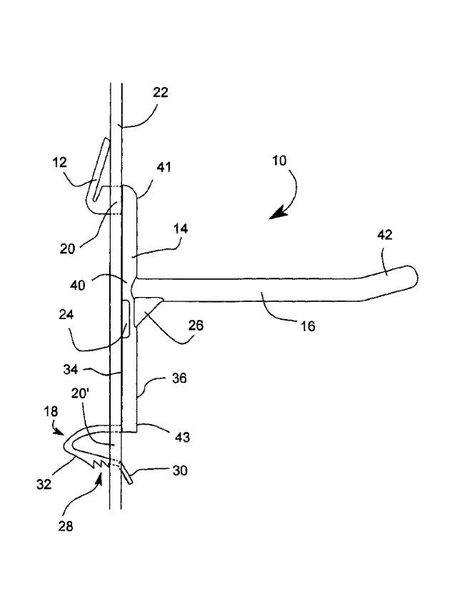
A hook for use with a pegboard comprising a L-shaped upper anchor attached to
the upper
portion of a vertical central body, a notch at a base portion of the upper
anchor to allow a
vertical member to flex, a U-shaped lower anchor inserted into a second hole
of the pegboard,
wherein the U-shaped lower anchor is attached to the lower portion of the
vertical central body,
the U-shaped lower anchor comprises a rigid member, a flexible member, a lever
and a plurality
of teeth aligned in a single row so that one of said teeth can cling to an
edge of the second hole
of the pegboard. The hook would better adapt to various pegboard thicknesses
than known
hooks.


Abrégé anglais

Il est décrit un crochet destiné à être utilisé avec un panneau perforé comprenant une ancre supérieure en forme de L fixée à la partie supérieure dun corps central vertical, une encoche à une partie de base de lancre supérieure pour permettre à un élément vertical de fléchir, une ancre inférieure en forme de U insérée dans un deuxième trou du panneau perforé, dans lequel lancre inférieure en forme de U est fixée à la partie inférieure du corps vertical central, lancre inférieure en forme de U comprend un élément rigide, un élément souple, un levier et une pluralité de dents alignés dans une seule rangée, de telle sorte que lesdites dents puissent sagripper à un bord du deuxième trou du panneau perforé. Le crochet sadapterait mieux à diverses épaisseurs du panneau perforé que les crochets connus.

Revendications

Note : Les revendications sont présentées dans la langue officielle dans laquelle elles ont été soumises.


7
CLAIMS
What is claimed is:
1. A hook for use with a pegboard comprising:
a vertical central body having a flat back side, a front side, an upper
portion, central portion, and
a lower portion;
a L-shaped upper anchor inserted into a first hole of the pegboard, wherein
the L-shaped upper
anchor is attached to the upper portion of the vertical central body;
a U-shaped lower anchor inserted into a second hole of the pegboard, wherein
the U-shaped
lower anchor is attached to the lower portion of the vertical central body;
and,
a horizontal rod for hanging objects, wherein the horizontal rod is attached
to the front side of
vertical central body approximate to the central portion; the U-shaped lower
anchor comprises a rigid
member, a flexible member, a lever and a plurality of teeth aligned in a
single row so that one of said
teeth can cling to an edge of the second hole of the pegboard;
a notch at a base portion of the upper anchor to allow a vertical member to
flex so as to adapt to various
pegboard thicknesses.
2. The hook of claim 1, wherein the flat back side is flush with the
pegboard during use.
3. The hook of claim 1, further comprising a reinforcement rib positioned
between a lower side of
the horizontal rod and the front side of the vertical central body for
support.

8
4. The hook of claim 1, further comprising a wing attached to each side of
the vertical central
body approximate to the central portion.
5. The hook of claim 1, wherein the horizontal rod includes a raised end to
secure a hanged object
on the horizontal rod.
6. The hook of claim 1, wherein the L-shaped upper anchor consists
essentially of a horizontal
member, a vertical member, and a notch, wherein the notch accommodates varying
pegboard
thicknesses.
7. The hook of claim 1 wherein the lever disengages the tooth of the
plurality of teeth from the
second hole of the pegboard allowing the removal of the hook.

Description

Note : Les descriptions sont présentées dans la langue officielle dans laquelle elles ont été soumises.


1
IMPROVED HOOK FOR PEGBOARD
BACKGROUND OF THE INVENTION
1. Field of the Invention
Il] The present invention relates generally to a hook but more particularly
to an improved hook
for use with a pegboard.
2. Description of Related Art
[2] The use of hooks in pegboards is well known. Existing hooks of the
prior art are made from
metal rods, and the hooks allow tools and other objects to be stored on a flat
surface, such as wall.
However, the hooks of the prior art have several disadvantages. Due to their
shape and connection
with holes of a pegboard, the hooks are easily dislodged from the holes when
aceidentally bumped into.
Specifically, any upward motion on a hook will dislodge it from a pegboard.
Further, when a user
attempts to retrieve a hanging object or tool from a hook on a pegboard, the
act of retrieving the object
often dislodges the hook from the pegboard, frustrating the user, and even
causing damage to the object
or hook, and possibly injury to the user. Consequently, an improved hook for
use with a pegboard is
needed.
CA 2998947 2019-05-15

2
BRIEF SUMMARY OF THE INVENTION
[31 In one embodiment of the present invention a hook for use with a
pegboard is provided,
comprising a vertical central body having a flat back side, a front side, an
upper portion, central
portion, and a lower portion; a L-shaped upper anchor configured to be
inserted into a first hole of the
pegboard, wherein the L-shaped upper anchor is attached to the upper portion
of the vertical central
body; a U-shaped lower anchor configured to be inserted into a second hole of
the pegboard, wherein
the U-shaped lower anchor is attached to the lower portion of the vertical
central body; and, a
horizontal rod for hanging objects, wherein the horizontal rod is attached to
the front side of vertical
central body approximate to the central portion.
141 In one embodiment, the flat back side is configured to be flush with
the pegboard during use. In
one embodiment, a reinforcement rib positioned between a lower side of the
horizontal rod and the
front side of the vertical central body is provided for support. In another
embodiment, a wing attached
to each side of the vertical central body approximate to the central portion
is provided. In one
embodiment, the horizontal rod includes a raised end configured to help secure
a hanged object on the
horizontal rod. In one embodiment, the L-shaped upper anchor consists
essentially of a horizontal
member, a vertical member, and a notch, wherein the notch is configured to
accommodate varying
pegboard thicknesses. In one embodiment, the U-shaped lower anchor comprises a
rigid member, a
flexible member, a plurality of teeth, and a lever. In yet another embodiment,
a tooth of the plurality of
teeth is configured to cling to an edge of the second hole of the pegboard. In
one embodiment, the
CA 2998947 2019-05-15

3
lever is configured to disengage the tooth of the plurality of teeth from the
second hole of the
pegboard allowing the removal of the hook
BRIEF DESCRIPTION OF THE SEVERAL VIEWS OF THE DRAWINGS
[51 Other features and advantages of the present invention will become
apparent when the
following detailed description is read in conjunction with the accompanying
drawings, in which:
[6] FIG. 1 is a side view of an improved hook for use with a pegboard
according to an
embodiment of the present invention;
[7] FIG. 2A is a side view of an upper anchor of the improved hook
according to an embodiment
of the present invention;
[8] FIG. 2B is an isometric view of FIG. 2A;
[9] FIG. 3A is a side view of a lower anchor of the improved hook according
to an embodiment of
the present invention; and,
[10] FIG. 3B is an isometric view of FIG. 3A.
DETAILED DESCRIPTION OF THE PREFERRED EMBODIMENT
CA 2998947 2019-05-15

4
Pl] The
following description is provided to enable any person skilled in the art to
make and use the
invention and sets forth the best modes contemplated by the inventor of
carrying out his invention.
Various modifications, however, will remain readily apparent to those skilled
in the art, since the
general principles of the present invention have been defined herein to
specifically provide an
improved hook for use with a pegboard.
1121 FIG. 1 is a side view of an improved hook 10 for use with a pegboard 22
according to an
embodiment of the present invention. Referring now to FIG. 1, the hook
comprises an upper anchor
12, a vertical central body 14, and a lower anchor 18. The hook further
comprises a horizontal rod 16
configured to hang tools and objects as well known in the art. In one
embodiment, the horizontal rod
includes a raised end 42 to help retain the tools and objects on the
horizontal rod. In one embodiment,
the horizontal rod is cylindrical, however it is understood that other shapes
may be used. In one
embodiment, the hook occupies three vertically aligned holes on the pegboard,
utilizing the first and
third hole. Specifically, the hook secures to the pegboard utilizing holes 20
and 20' and the upper and
lower anchor respectively. The upper and lower anchor will be described in
greater detail below.
113] In one embodiment, the vertical central body has a flat back side 34
configured to be flush
against the pegboard during use. In one embodiment, the vertical central body
has a rounded front
side 36 that is configured to accept the horizontal rod approximate to a
central portion 40 of the
vertical central body. A reinforcement rib 26 is provided between a lower side
36 of the horizontal
rod and the front side of the vertical central body for support. Similarly, a
wing 24 is provided on
each side of the vertical central body approximate to the central portion
providing stability against the
pegboard during use by increasing the lateral surface area touching the
pegboard.
CA 2998947 2019-05-15

5
[14] FIGS. 2A-B are views of the upper anchor according to an embodiment of
the present
invention. Referring now to FIGS. 2A-B, upper anchor 12 is illustrated. The
upper anchor is
constructed of an L-shape having a horizontal member 44 and a vertical member
46. ln one
embodiment, the upper anchor comprises a notch 13 allowing the upper anchor to
accommodate
varying pegboard thicknesses. In one embodiment, the notch is between the
horizontal and the
vertical member. The horizontal member is attached perpendicularly to an upper
portion 41 of the flat
back side of the vertical central body.
[15] FIGS. 3A-B are views of the lower anchor according to an embodiment of
the present
invention. Referring now to FIGS. 3A-B, lower anchor 18 is illustrated. The
lower anchor is
constructed of a U-shape having a rigid member 31 and a flexible member 32.
The lower anchor is
attached to a lower portion 43 of the flat back side of the vertical central
body. ln one embodiment,
the flexible member includes a plurality of teeth 28 configured to accommodate
different thicknesses
of pegboards. Specifically, the plurality of teeth is shaped to cling onto an
edge of a pegboard hole. It
is a particular advantage of the present invention, that the lower anchor is
configured to prevent
unintentional release of the hook during use. In one embodiment, the flexible
member includes a
lever 30 configured to disengage the plurality of teeth from the pegboard hole
allowing the removal of
the hook.
[16] During use, the upper anchor is inserted into first hole 20 of the
pegboard. Next, the lower
anchor is inserted into second hole 20' until a tooth of the plurality of
teeth catches the edge of the
second hole, securing the lower anchor to the pegboard. The upper member of
the upper anchor
presses against the backside of the pegboard during use providing additional
securement. The lever is
accessible on the front side of the pegboard as illustrated in FIG. 1 for
removal as previously described.
CA 2998947 2019-05-15

6
[17] Although the invention bas been described in considerable detail in
language specific to
structural features, it is to be understood that the invention defined in the
appended daims is not
necessarily limited to the specific features described. Rather, the specific
features are disclosed as
exemplary preferred forms of implementing the claimed invention. Stated
otherwise, it is to be
understood that the phraseology and terminology employed herein, as well as
the abstract, are for the
purpose of description and should flot be regarded as limiting. Therefore,
while exemplary illustrative
embodiments of the invention have been described, numerous variations and
alternative embodiments
will occur to those skilled in the art. Such variations and alternate
embodiments are contemplated, and
can be made without departing from the spirit and seope of the invention.
[18] It should further be noted that throughout the entire disclosure, the
labels such as left, right,
front, back, top, bottom, forward, reverse, clockwise, counter clockwise, up,
down, or other similar
terms such as upper, lower, aft, fore, vertical, horizontal, oblique,
proximal, distal, parallel,
perpendicular, transverse, longitudinal, etc. have been used for convenience
purposes only and are flot
intended to imply any particular fixed direction or orientation. Instead, they
are used to reflect relative
locations and/or directions/orientations between various portions of an
object.
[19] In addition, reference to "first," "second," "third," and etc. members
throughout the disclosure
(and in particular, claims) are flot used to show a serial or numerical
limitation but instead are used to
distinguish or identify the various members of the group.
CA 2998947 2019-05-15

Dessin représentatif
Une figure unique qui représente un dessin illustrant l'invention.
États administratifs

Pour une meilleure compréhension de l'état de la demande ou brevet qui figure sur cette page, la rubrique Mise en garde , et les descriptions de Brevet , États administratifs , Taxes périodiques et Historique des paiements devraient être consultées.

États administratifs

Titre Date
Date de délivrance prévu 2020-09-01
(22) Dépôt 2018-03-22
(41) Mise à la disponibilité du public 2018-10-26
Requête d'examen 2019-01-17
(45) Délivré 2020-09-01

Historique d'abandonnement

Il n'y a pas d'historique d'abandonnement

Taxes périodiques

Dernier paiement au montant de 100,00 $ a été reçu le 2024-03-07


 Montants des taxes pour le maintien en état à venir

Description Date Montant
Prochain paiement si taxe applicable aux petites entités 2025-03-24 100,00 $
Prochain paiement si taxe générale 2025-03-24 277,00 $

Avis : Si le paiement en totalité n'a pas été reçu au plus tard à la date indiquée, une taxe supplémentaire peut être imposée, soit une des taxes suivantes :

  • taxe de rétablissement ;
  • taxe pour paiement en souffrance ; ou
  • taxe additionnelle pour le renversement d'une péremption réputée.

Les taxes sur les brevets sont ajustées au 1er janvier de chaque année. Les montants ci-dessus sont les montants actuels s'ils sont reçus au plus tard le 31 décembre de l'année en cours.
Veuillez vous référer à la page web des taxes sur les brevets de l'OPIC pour voir tous les montants actuels des taxes.

Historique des paiements

Type de taxes Anniversaire Échéance Montant payé Date payée
Le dépôt d'une demande de brevet 200,00 $ 2018-03-22
Requête d'examen 400,00 $ 2019-01-17
Taxe de maintien en état - Demande - nouvelle loi 2 2020-03-23 50,00 $ 2020-01-31
Taxe finale 2020-11-23 150,00 $ 2020-07-27
Taxe de maintien en état - brevet - nouvelle loi 3 2021-03-22 50,00 $ 2021-01-09
Taxe de maintien en état - brevet - nouvelle loi 4 2022-03-22 50,00 $ 2022-02-11
Taxe de maintien en état - brevet - nouvelle loi 5 2023-03-22 100,00 $ 2023-03-09
Taxe de maintien en état - brevet - nouvelle loi 6 2024-03-22 100,00 $ 2024-03-07
Titulaires au dossier

Les titulaires actuels et antérieures au dossier sont affichés en ordre alphabétique.

Titulaires actuels au dossier
TEAR, PAUL
Titulaires antérieures au dossier
S.O.
Les propriétaires antérieurs qui ne figurent pas dans la liste des « Propriétaires au dossier » apparaîtront dans d'autres documents au dossier.
Documents

Pour visionner les fichiers sélectionnés, entrer le code reCAPTCHA :


Pour visualiser une image, cliquer sur un lien dans la colonne description du document. Pour télécharger l'image (les images), cliquer l'une ou plusieurs cases à cocher dans la première colonne et ensuite cliquer sur le bouton "Télécharger sélection en format PDF (archive Zip)" ou le bouton "Télécharger sélection (en un fichier PDF fusionné)".

Liste des documents de brevet publiés et non publiés sur la BDBC .

Si vous avez des difficultés à accéder au contenu, veuillez communiquer avec le Centre de services à la clientèle au 1-866-997-1936, ou envoyer un courriel au Centre de service à la clientèle de l'OPIC.


Description du
Document 
Date
(yyyy-mm-dd) 
Nombre de pages   Taille de l'image (Ko) 
Paiement de taxe périodique 2020-01-31 3 51
Modification 2020-02-24 10 177
Revendications 2020-02-24 2 41
Abrégé 2020-05-27 1 15
Revendications 2019-08-29 2 52
Taxe finale 2020-07-27 2 54
Page couverture 2020-08-07 1 31
Dessins représentatifs 2020-08-07 1 9
Paiement de taxe périodique 2021-01-09 2 53
Paiement de taxe périodique 2022-02-11 2 53
Paiement de taxe périodique 2023-03-09 3 59
Revendications 2019-05-15 2 39
Abrégé 2018-03-22 1 10
Description 2018-03-22 6 194
Revendications 2018-03-22 2 40
Dessins 2018-03-22 3 22
Modification 2018-03-28 4 42
Dessins représentatifs 2018-09-24 1 5
Page couverture 2018-09-24 1 28
Requête d'examen 2019-01-17 1 25
Dessins 2018-03-28 3 23
Demande d'examen 2019-03-06 6 423
Modification 2019-05-15 17 407
Description 2019-05-15 6 206
Modification 2019-08-29 6 138
Modification 2019-08-29 1 25
Demande d'examen 2019-10-21 5 255
Paiement de taxe périodique 2024-03-07 3 64
Lettre du bureau 2024-03-28 2 188