Sélection de la langue

Search

Sommaire du brevet 3050476 

Énoncé de désistement de responsabilité concernant l'information provenant de tiers

Une partie des informations de ce site Web a été fournie par des sources externes. Le gouvernement du Canada n'assume aucune responsabilité concernant la précision, l'actualité ou la fiabilité des informations fournies par les sources externes. Les utilisateurs qui désirent employer cette information devraient consulter directement la source des informations. Le contenu fourni par les sources externes n'est pas assujetti aux exigences sur les langues officielles, la protection des renseignements personnels et l'accessibilité.

Disponibilité de l'Abrégé et des Revendications

L'apparition de différences dans le texte et l'image des Revendications et de l'Abrégé dépend du moment auquel le document est publié. Les textes des Revendications et de l'Abrégé sont affichés :

  • lorsque la demande peut être examinée par le public;
  • lorsque le brevet est émis (délivrance).
(12) Demande de brevet: (11) CA 3050476
(54) Titre français: BLOQUEUR PROTUBERANT DE PORTES DOTEES D`UN PISTON DE FERMETURE
(54) Titre anglais: PROTRACTING BLOCKER FOR DOORS EQUIPPED WITH A CLOSER PISTON
Statut: Conforme
Données bibliographiques
(51) Classification internationale des brevets (CIB):
  • E05C 17/02 (2006.01)
(72) Inventeurs :
  • RIOUX, ALAIN (Canada)
  • GOSSELIN, KEVIN (Canada)
(73) Titulaires :
  • RIOUX, ALAIN (Canada)
  • GOSSELIN, KEVIN (Canada)
(71) Demandeurs :
  • RIOUX, ALAIN (Canada)
  • GOSSELIN, KEVIN (Canada)
(74) Agent:
(74) Co-agent:
(45) Délivré:
(22) Date de dépôt: 2019-08-23
(41) Mise à la disponibilité du public: 2020-01-26
Licence disponible: S.O.
(25) Langue des documents déposés: Anglais

Traité de coopération en matière de brevets (PCT): Non

(30) Données de priorité de la demande:
Numéro de la demande Pays / territoire Date
1812227.5 Royaume-Uni 2018-07-26

Abrégés

Abrégé anglais


An angularly variable device for use on a door having a closer piston with a
piston arm wherein the
angularly variable device is a protracting blocker comprised of a first
section and a second section. Each
section comprises a wall from which extends at least one tab extending
perpendicularly therefrom. From
the wall extends generally perpendicularly at least one but preferably a
plurality of tabs so that the at
least one tab on each of the first section and the second section rests on top
of the piston arm. A retainer
presses against an elbow joint forming part of the piston arm so as to firmly
press the wall against the
piston arm so that one side of the blocker is pressed against one side of the
piston arm while the retainer
presses against the opposite side of the piston arm so as to provide a secure
installation of the blocker on
the piston arm. A lever pivoted into a horizontal position presses the two
sections together so that they
remain in a given fixed position relative to each other so as to immobilize
the piston arm in a given
position.

Revendications

Note : Les revendications sont présentées dans la langue officielle dans laquelle elles ont été soumises.


9
Claims
1. A protracting blocker for a door having a closer piston with a piston arm
wherein the
protracting blocker is comprised of a first section and a second section; each
section
comprises a wall from which extends at least one tab extending perpendicularly
therefrom;
from the wall extends generally perpendicularly at least one but preferably a
plurality of tabs
so that the at least one tab on each of the first section and the second
section rests on top of
the piston arm; a retainer presses against an elbow joint forming part of the
piston arm so as
to firmly press the wall against the piston arm so that one side of the
blocker is pressed
against one side of the piston arm while the retainer presses against the
opposite side of the
piston arm so as to provide a secure installation of the blocker on the piston
arm; a lever
pivoted into a horizontal position presses the two sections together so that
they remain in a
given fixed position relative to each other so as to immobilize the piston arm
in a given
position.
2. The protracting blocker of claim 1 wherein the first section and the second
section are
rotationally connected at an axis point through which passes a rod which has a
means for
biasing at its distal end, and has the lever pivotally attached at its
proximal end.
3. The protracting blocker of claim 1 wherein when the lever presses against
the first
section, it pushes the first section against the second section.
4. The protracting blocker of claim 3 wherein a first and a second sprocket
from the first
section meshes with a third and fourth sprocket located on the second section
by way of sets
of teeth forming part of the first, second, third and fourth sprockets so as
to immobilize the
first section and the second section.

10
5. The protracting blocker of claim 1 wherein the rod holds the first section
and the second
section together by way of attaching with the lever by way of a pin.
6. The protracting blocker of claim 1 wherein a bracket holds the retainer and
is pivotally
attached on top of the first section at the axis point by way of the rod
passing through a rod
hole.
7. The protracting blocker of claim 1 wherein the bracket has an opening made
through the
bracket so that a nipple extending perpendicularly from the retainer can be
inserted therein
to hold the retainer in place.
8. The protracting blocker of claim 1 wherein the second section has a bushing
acting as a
pivot point for the first section and the second section.
9. The protracting blocker of claim 1 wherein each of the first section and a
second section is
shaped like a "C" and comprises a top member, a bottom member and the wall to
join the top
member and bottom member.
10. A combination of a protracting blocker with a door having and a closer
piston having a
piston arm wherein the protracting blocker is comprised of a first section and
a second
section; each section comprises a wall from which extends at least one tab
extending
perpendicularly therefrom; from the wall extends generally perpendicularly at
least one but
preferably a plurality of tabs so that the at least one tab on each of the
first section and the
second section rests on top of the piston arm; a retainer presses against an
elbow joint
forming part of the piston arm so as to firmly press the wall against the
piston arm so that one
side of the blocker is pressed against one side of the piston arm while the
retainer presses
against the opposite side of the piston arm so as to provide a secure
installation of the blocker

11
on the piston arm; a lever pivoted into a horizontal position presses the two
sections together
so that they remain in a given fixed position relative to each other so as to
immobilize the
piston arm in a given position.
11. The combination of claim 10 wherein the first section and the second
section are
rotationally connected at an axis point through which passes a rod which has a
means for
biasing at its distal end, and has the lever pivotally attached at its
proximal end.
12. The combination of claim 10 wherein when the lever presses against the
first section, it
pushes the first section against the second section.
13. The combination of claim 12 wherein a first and a second sprocket from the
first section
meshes with a third and fourth sprocket located on the second section by way
of sets of teeth
forming part of the first, second, third and fourth sprockets so as to
immobilize the first
section and the second sections.
14. The combination of claim 10 wherein the rod holds the first section and
the second
section together by way of attaching with the lever by way of a pin.
15. The combination of claim 10 wherein a bracket holds the retainer and is
pivotally
attached on top of the first section at the axis point by way of the rod
passing through a rod
hole.
16. The combination of claim 10 wherein the bracket has an opening made
through the
bracket so that a nipple extending perpendicularly from the retainer can be
inserted therein
to hold the retainer in place.

12
17. The combination of claim 10 wherein the second section has a bushing
acting as a pivot
point for the first section and the second section.
18. The combination of claim 10 wherein each of the first section and a second
section is
shaped like a "C" and comprises a top member, a bottom member and the wall to
join the top
member and bottom member.

Description

Note : Les descriptions sont présentées dans la langue officielle dans laquelle elles ont été soumises.


1
Protracting blocker for doors equipped with a closer piston
BACKGROUND OF THE INVENTION
I. Field of the Invention
[1] The present invention relates generally to to door blocking mechanisms but
more particularly
to a protracting blocker for doors equipped with a closer piston.
2. Description of Related Art
121 Keeping open a door equipped with a closer piston can be quite annoying.
In some instances
those doors are equipped with a flip down friction stopper but when they;re
not, one has to
resolve to makeshift methods such as jamming a piece of wood between the door
and its casing,
which can result in damage to one or both parts. In other instances, one tries
to see if the piston
model makes it easy to disable it. Essentially, there is no one universal and
quick device to solve
this problem.
CA 3050476 2019-07-24

2
BRIEF SUMMARY OF THE INVENTION
[3] It is a main advantage of this invention to provide for a protracting
blocker for doors equipped
with a closer piston.
[4] In order to do so, the invention comprises an angularly variable device
for use on a door having
a closer piston with a piston arm wherein the angularly variable device is a
protracting blocker
comprised of a first section and a second section. Each section comprises a
wall from which
extends at least one tab extending perpendicularly therefrom. From the wall
extends generally
perpendicularly at least one but preferably a plurality of tabs so that the at
least one tab on each
of the first section and the second section rests on top of the piston arm. A
retainer presses
against an elbow joint forming part of the piston arm so as to firmly press
the wall against the
piston arm so that one side of the blocker is pressed against one side of the
piston arm while the
retainer presses against the opposite side of the piston arm so as to provide
a secure installation
of the blocker on the piston arm. A lever pivoted into a horizontal position
presses the two
sections together so that they remain in a given fixed position relative to
each other so as to
immobilize the piston arm in a given position.
[5] The first section and the second section are rotationally connected at an
axis point through
which passes a rod which has a means for biasing at its distal end, and has
the lever pivotally
attached at its proximal end.
[6] When the lever presses against the first section, it pushes the first
section against the second
section.
CA 3050476 2019-07-24

3
[7] A first and a second sprocket from the first section meshes with a third
and fourth sprocket
located on the second section by way of sets of teeth forming part of the
first, second, third and
fourth sprockets so as to immobilize the first section and the second section.
[8] The rod holds the first section and the second section together by way of
attaching with the
lever by way of a pin.
[9] A bracket holds the retainer and is pivotally attached on top of the first
section at the axis point
by way of the rod passing through a rod hole.
[10] The bracket has an opening made through the bracket so that a nipple
extending
perpendicularly from the retainer can be inserted therein to hold the retainer
in place.
[11] The second section has a bushing acting as a pivot point for the first
section and the second
section.
[12] Each of the first section and a second section is shaped like a "C" and
comprises a top
member, a bottom member and the wall to join the top member and bottom member.
[13] The protracting door blocker works in combination with a door having and
a closer piston
having a piston arm.
[14] The foregoing and other objects, features, and advantages of this
invention will become
more readily apparent from the following detailed description of a preferred
embodiment with
CA 3050476 2019-07-24

4
reference to the accompanying drawings, wherein the preferred embodiment of
the invention is
shown and described, by way of examples. As will be realized, the invention is
capable of other
and different embodiment, and its several details are capable of modifications
in various
obvious respects, all without departing from the invention. Accordingly, the
drawings and
description are to be regarded as illustrative in nature, and not as
restrictive.
BRIEF DESCRIPTION OF THE SEVERAL VIEWS OF THE DRAWINGS
[15] Other features and advantages of the present invention will become
apparent when the
following detailed description is read in conjunction with the accompanying
drawings, in which:
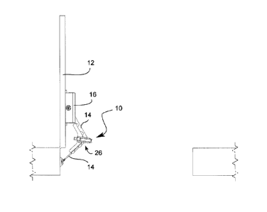
[16] FIG. 1 is a top view of the invention in context of use, according to an
embodiment of the
present invention.
[17] FIG. 2 is an isometric view, of the protracting blocker according to an
embodiment of the
present invention in its protracted configuration.
[18] FIGS. 3AB are a top and a cutaway side view, respectively, according to
an embodiment of
the present invention.
[19] FIGS. 4A-D are front views of the invention in open (protracted) and
closed (retracted)
positions and with the lever disengaging and engaging the sprockets,
respectively.
[20] FIG. 5 is an exploded view, according to an embodiment of the present
invention.
CA 3050476 2019-07-24

5
[21] FIGS. 6A-B are side views of the first section and the second section,
respectively,
according to an embodiment of the present invention.
[22] FIGS. 7A-C Top, side and front views, respectively, of the bracket,
according to an
embodiment of the present invention.
[23] FIGS. 8A-C Top, front, and side views, respectively, of the retainer,
according to an
embodiment of the present invention.
[24] FIG. 9 is an isometric view, of the protracting blocker according to an
embodiment of the
present invention in its retracted configuration.
DETAILED DESCRIPTION OF THE PREFERRED EMBODIMENT
[25] The following description is provided to enable any person skilled in the
art to make and use
the invention and sets forth the best modes contemplated by the inventor of
carrying out his
invention. Various modifications, however, will remain readily apparent to
those skilled in the
art, since the general principles of the present invention have been defined
herein to specifically
provide a pulling tool for a human-powered wheeled vehicle.
[26] Referring now to any of figs 1 through 3, a protracting blocker (10)
for a door (12) is
installed over a piston arm (14) of a closer piston (16). The protracting
blocker (10) is
CA 3050476 2019-07-24

6
comprised of a first and a second section (18, 18') wherein each of the
sections (18, 18') is
shaped like a "C" and comprises a top member (19), a bottom member (21) and a
wall (20) to
join the top and bottom members (19, 21). From the wall (20) extends generally
perpendicularly
at least one but preferably a plurality of tabs (22) so that the at least one
tab (22) on each
sections (18, 18') can rest on top of the piston arm (14). A retainer (24)
presses against an elbow
joint (26) forming part of the arm (14) so as to firmly press the wall (20)
against the piston arm
(14) so that one side of the blocker (10) is pressed up against one side of
the piston arm (14)
while the retainer (24) presses up against the opposite side of the piston arm
(14). The piston
(16) and piston arm (14) are well known in the art and need not be further
discussed here.
Suffice to say that the piston arm (14), much like a human arm, consists in an
upper arm, an
elbow, and a forearm. Here, the elbow joint (26) acts like a human elbow by
bending and is
hidden by a bracket (36) in FIG. 1. There is no need to explicitly show it
because of general
understanding of what the piston arm (14) is.
[27] In order to block the arm (14) from moving, a lever (28) is actuated,
which presses the two
sections (18, 18') together so that they become immobilized and as such,
immobilize the arm
(14) as well.
[28] The two sections (18, 18') are rotationally connected at an axis point
(30) through which
passes a rod (33) which has a means for biasing (34) at its distal end, and
has the lever (28)
pivotally attached at its proximal end. When the lever (28) presses against
the first section (18)
it pushes it against the second section (18'). More particularly, a first and
a second sprocket (32,
32') meshes with a third and fourth sprocket (32", 32") located on the second
section (18') by
way of sets of teeth (34) forming part of the sprockets (32, 32', 32", 32").
This effectively
CA 3050476 2019-07-24

7
immobilizes the two sections (18, 18'). The second section (18') has a bushing
(35) which is the
actual pivot point of the two sections (18, 18'), the rod (33) serving as a
retainer for both
sections (18, 18') as well as interacting with the lever (28) to create the
blocking. Also, a bracket
(36) for holding the triangular member (24) is pivotally attached on top of
the first section (18)
at the axis point by way of the rod (33) passing through a rod hole (31).
[29] Additional components include an opening (38) made through the bracket
(36) so that a
nipple (40) extending perpendicularly from the retainer (24) can be inserted
therein to hold the
retainer (24) in place. A pin (42) connects the lever (28) to the rod (33).
[30] Although the invention has been described in considerable detail in
language specific to
structural features, it is to be understood that the invention defined in the
appended claims is not
necessarily limited to the specific features described. Rather, the specific
features are disclosed
as exemplary preferred forms of implementing the claimed invention. Stated
otherwise, it is to
be understood that the phraseology and terminology employed herein, as well as
the abstract,
are for the purpose of description and should not be regarded as limiting.
Therefore, while
exemplary illustrative embodiments of the invention have been described,
numerous variations
and alternative embodiments will occur to those skilled in the art. Such
variations and alternate
embodiments are contemplated, and can be made without departing from the
spirit and scope of
the invention.
[31] It should further be noted that throughout the entire disclosure, the
labels such as left, right,
front, back, top, bottom, forward, reverse, clockwise, counter clockwise, up,
down, or other
similar terms such as upper, lower, aft, fore, vertical, horizontal, oblique,
proximal, distal,
CA 3050476 2019-07-24

8
parallel, perpendicular, transverse, longitudinal, etc. have been used for
convenience purposes
only and are not intended to imply any particular fixed direction or
orientation. Instead, they are
used to reflect relative locations and/or directions/orientations between
various portions of an
object.
1321 In addition, reference to "first," "second," "third," and etc. members
throughout the
disclosure (and in particular, claims) are not used to show a serial or
numerical limitation but
instead are used to distinguish or identify the various members of the group.
CA 3050476 2019-07-24

Dessin représentatif
Une figure unique qui représente un dessin illustrant l'invention.
États administratifs

Pour une meilleure compréhension de l'état de la demande ou brevet qui figure sur cette page, la rubrique Mise en garde , et les descriptions de Brevet , États administratifs , Taxes périodiques et Historique des paiements devraient être consultées.

États administratifs

Titre Date
Date de délivrance prévu Non disponible
(22) Dépôt 2019-08-23
(41) Mise à la disponibilité du public 2020-01-26

Historique d'abandonnement

Date d'abandonnement Raison Reinstatement Date
2024-02-23 Taxe périodique sur la demande impayée

Taxes périodiques

Dernier paiement au montant de 50,00 $ a été reçu le 2021-10-15


 Montants des taxes pour le maintien en état à venir

Description Date Montant
Prochain paiement si taxe applicable aux petites entités 2023-08-23 50,00 $
Prochain paiement si taxe générale 2023-08-23 125,00 $

Avis : Si le paiement en totalité n'a pas été reçu au plus tard à la date indiquée, une taxe supplémentaire peut être imposée, soit une des taxes suivantes :

  • taxe de rétablissement ;
  • taxe pour paiement en souffrance ; ou
  • taxe additionnelle pour le renversement d'une péremption réputée.

Les taxes sur les brevets sont ajustées au 1er janvier de chaque année. Les montants ci-dessus sont les montants actuels s'ils sont reçus au plus tard le 31 décembre de l'année en cours.
Veuillez vous référer à la page web des taxes sur les brevets de l'OPIC pour voir tous les montants actuels des taxes.

Historique des paiements

Type de taxes Anniversaire Échéance Montant payé Date payée
Le dépôt d'une demande de brevet 200,00 $ 2019-07-24
Taxe de maintien en état - Demande - nouvelle loi 3 2022-08-23 50,00 $ 2021-10-15
Taxe de maintien en état - Demande - nouvelle loi 2 2021-08-23 50,00 $ 2022-01-17
Surtaxe pour omission de payer taxe de maintien en état pour demande 2022-01-17 150,00 $ 2022-01-17
Titulaires au dossier

Les titulaires actuels et antérieures au dossier sont affichés en ordre alphabétique.

Titulaires actuels au dossier
RIOUX, ALAIN
GOSSELIN, KEVIN
Titulaires antérieures au dossier
S.O.
Les propriétaires antérieurs qui ne figurent pas dans la liste des « Propriétaires au dossier » apparaîtront dans d'autres documents au dossier.
Documents

Pour visionner les fichiers sélectionnés, entrer le code reCAPTCHA :


Pour visualiser une image, cliquer sur un lien dans la colonne description du document. Pour télécharger l'image (les images), cliquer l'une ou plusieurs cases à cocher dans la première colonne et ensuite cliquer sur le bouton "Télécharger sélection en format PDF (archive Zip)" ou le bouton "Télécharger sélection (en un fichier PDF fusionné)".

Liste des documents de brevet publiés et non publiés sur la BDBC .

Si vous avez des difficultés à accéder au contenu, veuillez communiquer avec le Centre de services à la clientèle au 1-866-997-1936, ou envoyer un courriel au Centre de service à la clientèle de l'OPIC.


Description du
Document 
Date
(yyyy-mm-dd) 
Nombre de pages   Taille de l'image (Ko) 
Dessins représentatifs 2019-12-20 1 4
Page couverture 2019-12-20 2 41
Correspondance reliée aux formalités 2020-02-04 8 217
Correspondance 2020-02-07 1 194
Correspondance 2020-02-07 1 191
Correspondance reliée aux formalités 2020-02-06 1 37
Taxe périodique + surtaxe 2021-10-15 3 70
Lettre du bureau 2021-11-29 2 207
Paiement de taxe périodique 2021-12-08 3 68
Correspondance taxe de maintien 2021-12-03 3 63
Remboursement 2022-01-17 3 56
Taxe périodique + surtaxe 2022-01-17 3 66
Lettre du bureau 2022-02-02 1 174
Lettre du bureau 2022-02-02 1 168
Remboursement 2022-02-04 4 235
Remboursement 2022-09-21 1 186
Correspondance reliée aux formalités 2019-08-23 3 60
Abrégé 2019-07-24 1 23
Description 2019-07-24 8 216
Revendications 2019-07-24 4 108
Dessins 2019-07-24 9 130
Correspondance reliée aux formalités 2019-07-24 4 108
Requête sous l'article 37 2019-08-09 1 54
Lettre du bureau 2019-08-09 1 68
Lettre du bureau 2024-04-17 2 188