Note : Les descriptions sont présentées dans la langue officielle dans laquelle elles ont été soumises.
1
WINDMILL ELECTRICAL POWER SYSTEM AND TORQUE ENHANCED
TRANSMISSION
FIELD OF THE INVENTION
[0001] The present specification relates generally to electrical power systems
and more
specifically to a system and method for generating electrical power using a
turbine blade in
conjunction with an energy storage device, motor, or generator and a torque-
enhanced
transmission comprised of speed increasers, speed decreasers, flywheels,
shafts, and clutch
assemblies.
BACKGROUND OF THE INVENTION
[0002] With the cost per kilowatt-hour being a determining factor for modern
alternative energy
sources and energy storage, renewable energy is an important factor. United
States Patent No.
7,108,095 (US 7108095') teaches a torque-enhanced gearbox that includes one-
speed increaser and
two-speed stages. The torque-enhanced gearbox of US 7108095 defines a torque
enhanced gearbox
that operates by increasing revolutions per minute (rpm) with the exponential
increase in the amount
of kinetic energy created being limited to the prime mover speed and
multiplied by the gear ratio of
the speed increaser. The larger gear ratios in conventional windmills cause
many problems, such as
downtime and an overall reduction in investment return for systems using them.
The large gear
ratios also put heavy stress on windmill components, requiring preventative
maintenance to combat
component deterioration and leading to a higher cost of operation. Large
multistage planetary
gearboxes do not provide energy storage, cost more, are subject to high
stress, and do not attach to
multiple generators or prime movers in a simplistic manner. Inverters,
synchronous generators are
limited in that they add costs and unwanted fluctuations to a power grid.
[0003] US 7108095 claims a torque-enhanced gearbox and a method of generating
power
using a speed increaser, flywheel, clutch, and speed decreaser to bring the
speed of the flywheel
assembly to a speed above the operating speed of the generator then stepping
down the output
shaft with a speed decreaser. Renewable energy sources, such as wind, solar,
hydroelectric, and
Date Recue/Date Received 2021-03-25
2
geothermal in general produce energy in slow varied low rpm ranges. Such
energy sources are
also more varied in amount of energy produced, time required for production of
energy, and any
forces created thereby. Many generators are designed to operate at speeds that
standard industry
gas or electric motors operate around. With the low cost per kilowatt-hour
being a determining
factor of today's alternative energy paths, a cost-effective way to harness a
wide range of input
speeds is needed.
[0004] Furthermore, US 7108095 teaches a gearbox that includes a single speed
increaser and
a single claim speed increaser can have a higher gear ratio that equals the
sum of multiple speed
increasers but limits features and benefits that might otherwise be provided
by the synergistic use
of multiple speed increasers. Some of the advantages of adding speed
increasers in multitude
include allowing for additional input-output speed combinations and reducing
costs by allowing
less expensive speed increaser options, like a pulley belt driven variable
speed pulley
transmission system.
[0005] Accordingly, there remains a need for improvement in the prior art.
SUMMARY OF THE INVENTION
[0006] In an embodiment of the present invention, there is provided a torque-
enhanced
transmission that can be applied to numerous applications as the rpm input
range is significantly
increased. For example, slow and intermittent input speeds are a significant
factor in the higher
cost of many renewable energy sources. Wind, solar, geothermal, and hydro are
sources of
energy that would benefit from the torque-enhanced transmission described
herein by reducing
cost per kilowatt-hour and adding energy storage for improved grid peak load
management.
High-speed applications like uninterrupted power supply (UPS) power systems
that require
50,000 rpm or more can use the torque-enhanced transmission to reach these
speeds while
producing alternating current (AC) and direct current (DC) power in one system
or using AC,
DC, and any other fuel type the application requires. Multiple speed stages
are a useful
improvement embodied in the present invention. Any motorized vehicle
propulsion system or
power generation system incorporating the torque-enhanced transmission
described herein has
greater options for power flow.
Date Recue/Date Received 2021-03-25
3
[0007] According to an embodiment, the torque-enhanced transmission produces
power from a
wide range of prime movers. The use of multiple stages that have at least one
layshaft attached to
each speed stage and an auxiliary torque-enhanced transmission integrated into
a motor-
generator flywheel bearing system provides a primary energy storage function.
The torque-
enhanced transmission is capable of achieving output speeds optimal for
electrical and
mechanical power while accepting any prime mover input speeds, input torque,
and input run
time. The generator and prime mover incorporated can be small, therefore
reducing the cost of
the system. In operation, the system speeds up to store maximum kinetic
energy, and output shaft
speed is reduced to multiply torque and match the desired generator rpm. The
energy storage
functionality maximizes the run time of the generator and improves grid
stability.
[0008] According to an embodiment, multiple speed increasers can allow the
mechanical
battery cells to reach speeds otherwise unattainable with a single-speed
increaser without
expensive gearing. The use of different cells discharging to the main shaft
having differed rates
enables a range of discharge times and allows the main shaft output to release
any load the
controller calculates. The flywheels in the torque-enhanced transmission
provide stress reduction
in the system, allowing for more cost-effective speed gearing through lower-
cost gearing while
also allowing the input speeds and max speed stage rotation speeds to have a
broader range.
Furthermore, the system allows the use of constant speed 2-pole induction
generators. According
to an embodiment, the last stage of the torque-enhanced transmission uses a
speed decreaser to
reach the desired speed while increasing the torque.
[0009] One solution to reach higher speeds using multiple speed increasers is
to increase a
single speed increaser's gear ratio, but the energy storage cells and kinetic
energy transfer to and
from the main shaft of embodiments of the present invention change the system
completely.
[0010] A single-speed increaser with a larger gear ratio drives the flywheel
apparatus at a
single speed, and input shafts connected to a single drivetrain cannot deliver
the mechanical
power stored with as much balance as the measure required to maximize kinetic
energy flow
through the system. The large single gear ratio of US 7108095 with the first
speed stage sized
system components covers rpm ranges from 0 to max operating speed. According
to an
embodiment, the torque-enhanced transmission of the present invention steps up
the speed while
Date Recue/Date Received 2021-03-25
4
not under load. Energy storage devices may be connected to each speed stage
layshaft, thereby
allowing multiple points to receive and deliver mechanical energy to the
integrated motor-
generator bearing flywheel rotor assembly of each auxiliary output shaft.
According to an
embodiment, the motor-generator magnetic bearing flywheel rotor assembly is
used as a kinetic
energy storage device.
[0011] According to an embodiment, the speed stages provide a platform where
one speed
stage is a function of another. For example, wind turbine blades might operate
at 36 rpm, the first
speed stage at 180 rpm, the second speed stage at 900 rpm, the third speed
stage at 4500 rpm, the
fourth speed stage at 22500 rpm, and so on for as many stages as needed.
According to an
embodiment, each speed stage has components sized for the speeds in its
operating location.
According to an embodiment, each speed stage has a perpendicular or layshaft
that allows for
power flow to multiple smaller generators via an ancillary or an auxiliary
torque-enhanced
transmission. The method and designs described herein for embodiments of the
invention are not
choice or design preference but, rather, a means of solving a practical
problem directed to energy
generation. According to an embodiment, the speed stages and multiple speed
increasers
transform the gearbox of the prior art into a mechanical battery drivetrain.
According to an
embodiment, the higher speeds increase run time with a longer and lower
discharge of kinetic
energy to the main drive shaft, requiring constant output.
[0012] According to an embodiment, there are multiple speed stages and
multiple speed
increasers that allow multiple speed stages, which are used to maximize
kinetic energy storage,
and each speed stage may have at least one layshaft with an auxiliary torque
enhanced
transmission that stores kinetic energy or a lay or perpendicular shaft
connected to kinetic energy
storage systems. According to an embodiment, the torque-enhanced transmission
functions as a
mechanical battery drive train. According to an embodiment, the torque-
enhanced transmission
allows low rpm input applications to reach the high speeds required for cost-
effectiveness and
efficiency by adding speed increasers in smaller but multiple speed stages.
According to an
embodiment, auxiliary layshafts are the only way to achieve an efficient flow
of kinetic energy
back and forth from the auxiliary output shafts to the main drive shaft.
Date Recue/Date Received 2021-03-25
5
[0013] According to an embodiment, the torque-enhanced transmission has
multiple speed
stages, each with layshafts connected to an auxiliary torque-enhanced
transmission at each stage,
allowing the energy stored as kinetic energy to be discharged in small amounts
and stored at high
speeds in the motor-generator storage device that allows the torque-enhanced
transmission to
function as a mechanical battery and the energy to be discharged more
efficiently. According to
an embodiment, the torque-enhanced transmission improves peak loads in a grid
and provides
energy storage solutions for renewable energy sources.
[0014] Other aspects and features according to the present application will
become apparent to
those ordinarily skilled in the art upon review of the following description
of embodiments of the
invention in conjunction with the accompanying figures.
BRIEF DESCRIPTION OF THE FIGURES
[0015] The principles of the invention may better be understood with reference
to the
accompanying figures provided by way of illustration of an exemplary
embodiment, or
embodiments, incorporating principles and aspects of the present invention,
and in which:
[0016] FIGs. 1(a) and 1(b) show a turbine electrical system with a torque-
enhanced
transmission, according to an embodiment; and
[0017] FIG. 2 shows a turbine electrical system with a torque-enhanced
transmission with
multiple torque generators for storing kinetic energy, according to an
embodiment.
DETAILED DESCRIPTION OF EMBODIMENTS OF THE INVENTION
[0018] The description that follows, and the embodiments described therein,
are provided by
way of illustration of an example, or examples, of particular embodiments of
the principles of the
present invention. These examples are provided for the purposes of
explanation, and not of
limitation, of those principles and of the invention. In the description, like
parts are marked
throughout the specification and the drawings with the same respective
reference numerals. The
Date Recue/Date Received 2021-03-25
6
drawings are not necessarily to scale and in some instances proportions may
have been exaggerated
in order to more clearly to depict certain features of the invention.
[0019] Framing the Need for a Turbine Electrical System Incorporating a Torque-
Enhanced Transmission
[0020] There is a need for a torque-enhanced transmission capable of accepting
a more
comprehensive range of input speeds and achieving output speeds that maximize
energy storage
while delivering a constant output speed, thus allowing for smaller, lighter,
and lower-cost
components in comprising a windmill.
[0021] According to an embodiment, the addition of multiple speed stages in a
flywheel
transmission may offer a cost reduction resulting from a reduction in gearing
system stress and the
use of simpler parts. According to an embodiment, a turbine electrical system
may incorporate a
torque-enhanced transmission with multiple flywheels, speed increasers, at
least one speed
decreaser, shafts, and clutches.
[0022] Renewable energy sources such as wind, solar, hydroelectric, and
geothermal in general
produce energy in slow, varied rpm ranges. Such energy sources are also
infrequent or variable in
the amount of energy produced, the time required for production of energy, and
any forces created
thereby. Many generators operate at speeds matching the speeds gas or electric
motors widely
use or make available. According to an embodiment, some of the advantages of
adding multiple
speed increasers include allowing for additional input-output speed
combinations, increased
kinetic energy, reduced cost of gearing, and reduced system stress to, for
example, enable the
gearing to be a belt-driven variable speed pulley transmission system.
According to an
embodiment, the relatively constant speed main drive shaft of the torque-
enhanced transmission
has multiple lay output shafts that allow for energy storage, energy transfer,
and energy
discharge of kinetic energy to be measured for efficient energy storage.
According to an
embodiment, the torque-enhanced transmission allows a broader range and
preferred type of AC
generator to be used and has a smaller output size and only two poles.
According to an
embodiment, the main drive shaft with multiple speed stages allows for
multiple layshafts, and
each layshaft has an auxiliary torque-enhanced transmission integrated into a
motor-generator
magnetic bearing assembly for energy storage.
Date Recue/Date Received 2021-03-25
7
[0023] According to an embodiment, there is a need for speed increasers after
each flywheel and
a perpendicular or parallel shaft at each speed stage allowing traditional
gears to be replaced by
lower cost speed increasers or decreasers as well as multiple ports to attach
additional prime movers
and multiple power output options.
[0024] According to an embodiment, the torque-enhanced transmission can be
applied to
numerous applications as it is compatible with a broad rpm input range. For
example, slow and
intermittent input speeds are a major factor in the higher cost of many
renewable energy sources.
Wind, solar, geothermal, and hydro are sources of energy that would benefit
from embodiments of
the torque-enhanced transmission by reducing the cost per kilowatt-hour and
adding energy storage
for improved grid peak load management. High speed applications like UPS power
systems that
require 50,000 rpm or more can use embodiments of the torque-enhanced
transmission to reach
these speeds while producing AC and DC power in one system or using AC, DC, or
any other fuel
type an application requires.
[0025] According to an embodiment, multiple speed stages are a useful
improvement that can be
used to produce power from a wide range of prime movers. According to an
embodiment, the
torque-enhanced transmission includes multiple flywheels, clutches, and
multiple speed increasers
to replace the use of a single large ratio speed increaser and gears can be
used in place of each. The
multiple speed stages of embodiments may have perpendicular shafts attached to
each speed stage
to comprise the torque-enhanced transmission.
[0026] Embodiments of the torque-enhanced transmission are capable of
achieving output speeds
that are optimal for electrical and mechanical power while accepting prime
mover input speeds,
input torque, and variable run times. Generators and prime movers may be
smaller, therefore
reducing cost, or separated or sized equal to or greater than traditional
sizes used in accordance with
traditional sizing calculations.
[0027] According to an embodiment, the turbine electrical system speeds up to
store maximum
kinetic energy and captures peak input from the energy source, then gears down
the output speed to
a desired rpm for a given application in a way that reduces cost, improves
efficiency of the
generator, and captures more input power from a source while providing peak
load power. Also
provided may be energy storage for maximizing the grid demands for electricity
or the mechanical
Date Recue/Date Received 2021-03-25
8
power needed to move vehicles with high weight, the speed and torque needed to
perform while
using a smaller sized prime mover or multiple fuel prime movers, hybrid
electric in any percent
range so as to allow a smaller step in charging techniques, and mechanical
batteries and other
battery technology while at the same time encouraging evolution by allowing
generational steps
towards electric transportation systems. For example, a vehicle can have a
reduced size prime
mover, but top end speeds are reduced. Embodiments of the torque-enhanced
transmission may be
attached to the drive shaft to produce mechanical power and is engaged for
peak loads. The prime
mover can be a small electric motor and the gasoline engine may be reduced by
a significant size.
According to an embodiment, an all-electric vehicle can have the same small
motor in addition to its
electric motor prime mover wherein it acts as a turbo charger for an electric
car as electric motor
torque is constant and excess torque goes to the torque-enhanced transmission
then to mechanical or
electrical power. According to an embodiment, the turbine electrical system
can generate power
from regenerative breaking as power flows back from the wheel to recharge the
battery or to aid a
fossil fuel engine, therefore reducing size.
[0028] According to an embodiment, adding multiple speed stages in a flywheel
transmission
offers a cost reduction in gearing and generators. Efficiency is increased by
the transmissions
relatively constant output speed. Multiple speed increasers can accept lower
rpms and achieve
higher output speeds. While one solution may be to use a larger ratio of a
single speed increaser,
this is an inferior and less effective system and transmission of power.
According to an
embodiment, the flywheels of the torque-enhanced transmission may operate as
energy storage
devices and act as a source of stress reduction in the system, thus allowing
more cost-effective
speed increasers. With lower stress on the system, lower cost gearing can be
used while allowing
the input speeds as well as output speeds to have a wider range. According to
an embodiment, the
turbine electrical system allows a constant speed induction generator to be
used and an inverter to be
omitted from electrical generating systems.
[0029] The large gear ratios in conventional windmills cause many problems,
including
downtime and an overall reduction in return on investment for systems using
them. The large gear
ratios put heavy stress on windmill components and lead to a higher cost of
operation. Large
multistage planetary gearboxes do not provide energy storage, cost more, and
are under high stress
and do not attach to multiple generators or prime movers with the simplicity
of embodiments of the
Date Recue/Date Received 2021-03-25
9
present invention. Inverters, synchronous generators add costs and unwanted
fluctuations in the
grid. Induction generators have a much smaller operating rpm range and
embodiments of the
torque-enhanced transmission allow a solution to the induction generator's
small, relatively constant
rpm operating range. Particularly, the relatively constant and multiple output
speeds of
embodiments of the torque-enhanced transmission allow for an induction type
generator to be used
as well as its size to be reduced and the multiple speed stages allow for
multiple types of generators
of smaller size to be used where the sum of the multiple smaller generators or
power applications
equals the power output of one larger generator used in other electrical or
mechanical power
applications that use traditional gearboxes.
[0030] Embodiments of the torque-enhanced transmission are a needed
improvement over other
transmissions used in traditional windmills, power generation systems, and
electrical generation
systems. The addition of speed increasers in several stages allows different
speeds to be outputted at
constant rpms. A single speed increaser with a larger gear ratio drives the
flywheel apparatus at a
single speed and different speeds complete the flow from input to output
quicker and for longer at
discharge. The speed stages provide a platform where one stage is a function
of the next, thus
reducing stress on the system and the cost of gearing. Generator size may also
be reduced if the
turbine electrical system is to run for longer with lower output if the speeds
can be designed for in a
cost-effective way. For example, wind turbine blades might operate at 36 rpm
and a single speed
increaser would not be able to be a simple, efficient, and cost-effective
component if its ratio were 5
to 1. According to embodiments of the invention, the flywheel of the first
speed stage may be set at
180 rpm, the second speed stage at 900 rpm, the third speed stage at 4500 rpm,
the fourth speed
stage at 22500 rpm, and so on for as many stages as needed. The large gear
ratio of large
conventional windmill gearboxes is susceptible to breakdown and are expensive.
By contrast,
embodiments of the torque-enhanced transmission steps up the speed while not
under load and
the energy storage device aspect allows for multiple points to increase speed
while maintaining
its primary job as an energy storage device.
[0031] According to an embodiment, each speed stage may have a perpendicular
or layshaft
that allows for power to be delivered to multiple smaller generators or to
mechanical power
applications. The method and system designs described herein are not simply a
different way to
accomplish what a single larger gear ratio speed increaser would accomplish.
Instead, adding
Date Recue/Date Received 2021-03-25
10
multiple stages and multiple speed increases allows for a greatly improved
system. The higher
speeds needed to use an induction type generator, provide backup power, and
providing peak
load protection requires multiple speed increasers to maximize the benefits in
generating power
as well as lowering cost and allowing for multiple prime movers and a variety
of generators to be
used.
[0032] According to an embodiment, permanent magnet generators (PMG) can
benefit from
the torque-enhanced transmission. The torque-enhanced transmission allows for
a much smaller
diameter and may reduce the number of permanent magnets needed, thereby
reducing the PMG
size. According to an embodiment, the speed increasers may work in reverse
during system
shutdown by draining the power from the system after the induction type
generator falls below
its operating range. According to an embodiment, a PMG can be used to charge
the battery
system that supplies power to a small electric motor used to maintain the
system's speed during
times of no wind or power input or if the energy would be better used later.
According to an
embodiment, the torque-enhanced transmission is a mechanical battery when a
motor and a
generator are attached. According to an embodiment, there may be a battery
that produces and
outputs AC power and works as a hybrid type battery when used with DC battery
types.
Embodiments of the invention may incorporate magnetic bearings or the torque-
enhanced
transmission may be enclosed in a vacuum, such as in a vacuum chamber.
[0033] According to an embodiment, the torque-enhanced transmission can be
used to
eliminate or ameliorate limitations found in gearboxes of permanent magnet
direct drive systems.
For example, large diameters are needed in these generators to make up for
very slow input
speeds. In direct drive systems the radius of the generator is made larger
because of the low input
speeds and these generator types use rare earth magnets, thereby increasing
the cost of the
system. An inverter is still required, and the size of the components cannot
be reduced and,
therefore, cost more. According to an embodiment, the large diameter of the
stator could be
retrofitted and used as a flywheel in the torque-enhanced transmission to
allow a more compact
hub even with a small gear ratio while using a PMG and an induction generator
in the same
system. While the gearbox is eliminated, the direct drive PMG, the extra-large
diameter of the
generator, use of rare permanent magnets, high cost inverter, and lack of
energy storage makes,
by comparison, embodiments of the torque-enhanced transmission of great
practical and
Date Recue/Date Received 2021-03-25
11
economic value. Embodiments of the torque-enhanced transmission would be
useful with these
generator types by reducing the diameter where magnets are needed. Further,
using the torque-
enhanced transmission allows both induction and PMG to be used in one system.
Embodiments
of the torque-enhanced transmission also allows multiple generators of
different types to be used
in one system while reducing the stress and cost of the system.
[0034] According to an embodiment, the range of acceptable input and output
speeds and other
benefits described herein may improve other power generating systems.
Incorporating
embodiments of the torque-enhanced transmission will allow generator prime
mover
combinations to previously cost prohibitive applications. For example, ocean
wave energy can be
extracted and stored in the system to produce mechanical or electrical energy
for a marine vessel.
Embodiments of the torque-enhanced transmission are useful as energy can be
stored or
generator size may be reduced or divided into smaller generators of different
types all while
increasing efficiency of the generator and capturing more energy from more
difficult forms of
energy. Embodiments may also improve peak loads in the grid and rectify energy
storage issues
some renewable energy sources have. Using multiple speed increasers allows
multiple speed
stages that are used to maximize final stage speed and kinetic energy storage
and allows a
perpendicular or parallel shaft to be attached at each speed stage to provide
further options as to
the number and type of prime movers and generators or mechanical power outputs
used.
Flywheels in embodiments may act as energy storage devices, allow a wide range
of acceptable
speeds, as well as reduce system stress. Modularity in design permits the
addition of speed
increasers or perpendicular or parallel shafts at each stage of the torque-
enhanced transmission.
[0035] According to an embodiment, the torque-enhanced transmission allows low
rpm input
applications to reach the high speeds needed in a cost effective and efficient
way and adding
speed increasers in smaller but multiple gear ratios is the only way to
achieve this. The use of
multiple speed increasers is only beneficial because of the flywheels and the
need to maximize
speed with low stress on the system. One approach would be to increase the
gear ratio of a single
speed increaser, but the benefits of the embodiments described herein would
then not be
applicable. Simply increasing the gear ratio of speed increasers in the prior
art causes more stress
on the gears, limit flywheel design options, and limit the possible rpm input-
output
Date Recue/Date Received 2021-03-25
12
combinations. Furthermore, higher rpm speeds can be achieved with multiple
speed increasers
without the challenges associated with large ratio gearboxes.
[0036] Accordingly, one object of embodiments of the present invention is to
provide a power
generation system that is less expensive while expanding the range of
acceptable input speeds
and input methods while offering many generator size and type ranges, thereby
increasing the
number of applications it may be directed to. Costs are reduced with the use
of a smaller
generator and the same output can be achieved with smaller generators by
increasing run time.
Furthermore, multiple small generators can be used with the output being the
same as a single
large generator. The prime mover can be sized larger or smaller in embodiments
with no needed
adjustment to the size of other components of the system.
[0037] According to an embodiment, the turbine electrical system includes a
renewable energy
source, a torque-enhanced transmission or torque-enhanced gearbox, wherein
there are multiple
flywheels of different sizes and operating at different speeds in different
stages with magnetic
bearings to create a less stressful workload, along with a reduced size
induction generator, while
providing increased production and peak load for a grid. A multistage
configuration with speed
increasers at different stages provides multiple benefits over prior art,
which simply increase the
gear ratio of a single speed increaser and thereby causes more stress on the
gears, limits flywheel
design options, and limits the possible rpm input-output combinations. For
example, shafts
connected parallel or perpendicular to a main shaft allows for a more
application specific system
design.
[0038] Preferred Embodiments
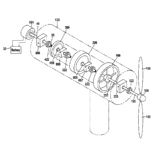
[0039] According to an embodiment shown in FIGs. 1(a) and 1(b), a turbine
electrical system
may be comprised of windmill turbine blades 100; a windmill turbine axis 105;
shafts 35, 40,
155, 255, 355, and 455; clutches 122, 222, 322, and 422; speed increasers 333,
667, and 999;
flywheels 199, 299, and 399; speed decreaser 888; torque enhanced transmission
123; a motor or
generator or energy storage device 901; and battery bank 32. At least one
shaft, clutch, flywheel,
and speed increaser or speed decreaser may be combined to provide a speed
stage. For example,
shaft 255, clutch 222, flywheel 199, and speed increaser 333 may be combined
to provide a first
speed stage. Flywheels may also be of a diameter that permits fitting of some
flywheels inside
Date Recue/Date Received 2021-03-25
13
the drum of another, like that of flywheel 399 within flywheel 299 within
flywheel 199 as shown
in the embodiment depicted in FIG. 1(b). The speed decreaser 888 may be
coupled to shaft 40
which operates as an electrical machine output shaft to operate motor or
generator or energy
storage device 901, which may be a two-pole induction generator, at a constant
speed. According
to an embodiment, auxiliary layshafts may extend outwards from the main
shafts, wherein the
auxiliary layshafts have smaller torque enhanced electrical machines that
operate at speeds much
higher than the main shafts. These layshaft generators may be used to
primarily store energy and
generate torque rather than electricity. Embodiments may also supply constant
output speed to a
main shaft generator, with electrical output to all be generated by the main
shaft generator.
[0040] According to an embodiment shown in FIG. 2, a turbine electrical system
may be
comprised of windmill turbine blades 100; a windmill turbine axis 105; shafts
155, 255, 355,
455, 555, 655, and 755; clutches 122, 222, 322, 422, 522, and 622; speed
increasers 110, 333,
667, and 999; flywheels 199, 299, 399, 499, 599, and 699; speed decreaser 888;
torque enhanced
transmission 123; a motor or generator or energy storage device 901; auxiliary
shafts 772, 773,
774, 775, 776, 777, 778, and 779; auxiliary torque-enhanced transmissions 12;
auxiliary motors,
auxiliary generators, or auxiliary energy storages devices 902, 903, 904, 905,
906, 907, 908, and
909; and battery bank 32. At least one shaft, clutch, flywheel, and speed
increaser or speed
decreaser may be combined with auxiliary shafts, auxiliary torque-enhanced
transmissions,
auxiliary motors, auxiliary generators, or auxiliary energy storage devices to
provide a speed
stage. For example, shaft 355, clutch 322, flywheel 299, and speed increaser
667 may be
combined with auxiliary shafts 772 and 777, two auxiliary torque-enhanced
transmissions 12,
and auxiliary motors, auxiliary generators, or auxiliary energy storages
devices 908 and 909 to
provide a second speed stage. The motor, generator, or energy storage device
901 may be a
primary induction generator whereas the auxiliary motors, auxiliary
generators, or auxiliary
energy storages devices 902, 903, 904, 905, 906, 907, 908, and 909 can
generate torque to the
shafts 155, 255, 355, 455, 555, 655, and 755 or may receive mechanical power
resulting from the
rotation of the turbine blades 100. Two of auxiliary shafts 772, 773, 774,
775, 776, 777, 778, and
779 may be connected to a given speed stage.
[0041] According to an embodiment, at least one flywheel may be a spoked
flywheel with a
weighted outer perimeter. According to a further embodiment, the weighted
outer perimeter may
Date Recue/Date Received 2021-03-25
14
weigh approximately 2200 kg. According to an embodiment, a first flywheel may
be designed
such that an at least second flywheel does not fit inside so that multiple
layshafts can be attached
in a 360-degree design.
[0042] According to an embodiment, wind turbine blades can deliver more energy
to a torque-
enhanced transmission as all speeds deliver energy to the torque-enhanced
transmission and
interior speeds achieved by the torque-enhanced transmission's energy storage
devices may
exceed those speeds required by a generator. However, a speed decreaser
delivers a target rpm
by down gearing, while concomitantly increasing torque. The use of different
speed stages in
embodiments allows for large torque transfer from peak wind and any layshaft
electrical
machines. In this regard, the layshaft design is crucial as the system's power
flow allows energy
to be stored while also performing the essential duty of acting as a torque
overflow pressure
relief valve.
[0043] According to an embodiment, the torque-enhanced transmission operates
with varied
speed in different stages in order to operate a constant speed induction
generator with minimal
variation in rpm range, thus reducing stress on the system while increasing
system efficiency.
[0044] Various embodiments of the invention have been described in detail.
Since changes in
and or additions to the above-described best mode may be made without
departing from the
nature, spirit or scope of the invention, the invention is not to be limited
to those details but only
by the appended claims. Section headings herein are provided as organizational
cues. These
headings shall not limit or characterize the invention set out in the appended
claims.
Date Recue/Date Received 2021-03-25