Note : Les descriptions sont présentées dans la langue officielle dans laquelle elles ont été soumises.
Docket No. 0196-1CAPT
Patent
METHODS AND SYSTEMS FOR GREEN ENERGY CHARGING OF ELECTRICAL
VEHICLES
BACKGROUND
[0001] Growth in electrical vehicles in markets will drive an increase in the
electrical grid
demand. Limited grid infrastructure and generation resources call for
alternate methods to
sustainably support this increase in electrical vehicle (EV) charging
capacity.
[0002] In addition, individual sites that have access to utility power, have a
limit on the
sanctioned power they can draw from a grid. The additional load of EV charging
can more
than double or triple the normal consumption of such individual sites. This
necessitates a
substantial upgrade in the connection to the grid; such upgrades are time-
consuming and
expensive.
[0003] Individual site owners and governments recognize the environmental and
economic
benefit of renewable energy sources to power their sites and in particular for
addressing the
additional load of EV charging. However, incentives that make it possible to
adopt
renewable energy resources such as net-metering support, are not available or
not sufficient
in many countries and states.
[0004] Distributed electricity generation resources can be utilized in a
microgrid to support
EV charging. However, the commercial viability of such a system is challenged
by several
factors. For example, there is the uncertainty in the adoption rate of EV
charging as a
business. This makes the timeline for return on investment unknown. Second,
traditional
microgrid solutions do not have an attractive payback period and often have
lifetimes just
barely long enough to cover the payback period.
BRIEF SUMMARY
[0005] In one aspect, there is provided a microgrid system comprising a
microgrid
controller; the microgrid controller having a plurality of input energy
sources, the input
energy sources selected from at least a grid source; a generator source; a
battery and one or
more renewable energy sources; the microgrid controller having as output: the
battery, a site
load and an electric vehicle (EV) charging service; wherein at least one of
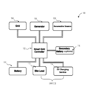
the site load and
1
Date Recue/Date Received 2020-10-30
Docket No. 0196-1CAPT
Patent
EV charging service are powered by a blend of the renewable energy source, the
battery, the
grid and the generator.
[0006] In some embodiments, excess power provided by at least one of the grid
source; the
generator source; and the one or more renewable energy sources is used to
charge the
battery.
[0007] In some embodiments, the microgrid controller directs the one or more
renewable
energy sources for EV charging while continuing to power the site load
uninterrupted.
[0008] In some embodiments, the battery powers at least one of the site load
and the EV
charging service if a state of charge of the battery is above a cyclic low
threshold.
[0009] In some embodiments, the microgrid further comprises a database
storing: one or
more source data structures, each source data structure associated with a
respective input
energy source, each data structure comprising information about the respective
input energy
source, the information comprising: one or time intervals during which the
respective input
energy source provides energy to the battery; and an amount of power provided
by the
respective input energy source to the battery during each time interval; and a
blend ratio
buffer, the blend ratio buffer comprising: a state of charge of the battery
and a split factor of
each input energy source during each time interval. A billing module can be
used to
determine billing for an episode of charging an electrical vehicle, the
billing module based
on: billing information for each input energy source; a direct contribution of
each input
energy source towards the episode; a blended contribution of each input energy
source
towards the episode, the blended contribution based on the blend ratio buffer;
and one or
more parameters of the battery. The billing can be determined after the
episode is complete,
or the billing may be continually evaluated during the episode.
[0010] In some embodiments, a second battery is connected as output and input
to the
microgrid controller, and the second battery is detachable from the microgrid
system. The
second battery may be embedded as a main battery in an electric vehicle. The
second
battery can be empty, partially charged or fully charged when connected to the
microgrid.
The second battery may not be used by the microgrid to charge the battery or
the electric
vehicle.
2
Date Recue/Date Received 2020-10-30
Docket No. 0196-1CAPT
Patent
[0011] In some embodiments, the microgrid system further comprises a secondary
storage
guidance module for predicting one or more second battery specifics selected
from at least
one of: how many times a day to use the second battery; a time of day when to
use the
second battery; and a storage capacity of the second battery; the secondary
storage guidance
module using as input at least one of: an EV predictor module; a solar
predictor module; and
a system behaviour module. The EV predictor module can provides a prediction,
for a
given day, of at least one of: one or more EV occurrences and EV power
requirements for
each occurrence; the solar predictor module can provide a prediction for the
given day, of
solar illumination; and the system behaviour module can provide a prediction,
for the
given day, of at least one of: one or more energy shortfalls; power
consumption of the site;
and occurrences of a change of the input energy sources occurs. At least one
of the EV
predictor module, the solar predictor module and the system behaviour module
can be a
machine-learning based module.
[0012] In some embodiments, the microgrid system further comprises a dynamic
storage
optimization module for optimizing storage; the dynamic storage optimization
module using
as input at least one of: an EV predictor module; a solar predictor module; a
behaviour
module; and a cost function module. The EV predictor module can provide a
prediction, for
a given day, of at least one of: one or more EV occurrences and EV power
requirements for
each occurrence; the solar predictor module can provide a prediction for the
given day, of
solar illumination; and the system behaviour module can provide a prediction,
for the given
day, of at least one of: one or more energy shortfalls; power consumption of
the site; and
occurrences of a change of the input energy sources occurs; and the cost
function module
provides information about at least one of: time-based electricity rates;
selling rates for each
of the input energy sources; storage rates for each of the input energy
sources; and retrieval
rates for each of the input energy sources. 16. At least one of the EV
predictor module, the
solar predictor module and the system behaviour module may be a machine-
learning based
module.
[0013] In another aspect, there is provided a method of powering at least one
of a site load
and an electric vehicle (EV) charging service, the method comprising:
providing as input to
a microgrid controller of a microgrid, a plurality of input energy sources
selected from at
least a grid source; a generator source; a battery and one or more renewable
energy sources;
3
Date Recue/Date Received 2020-10-30
Docket No. 0196-1CAPT
Patent
providing as output by the microgrid controller: the battery, the site load
and the EV
charging service; wherein at least one of the site load and EV charging
service are powered
by a blend of the renewable energy source, the battery, the grid and the
generator.
[0014] In some embodiments, the method further comprises storing in a
database: one or
more source data structures, each source data structure associated with a
respective input
energy source, each data structure comprising information about the respective
input energy
source, the information comprising: one or time intervals during which the
respective input
energy source provides energy to the battery; and an amount of power provided
by the
respective input energy source to the battery during each time interval; and a
blend ratio
buffer, the blend ratio buffer comprising: a state of charge of the battery
and a split factor of
each input energy source during each time interval. A billing module can be
used to
determine billing for an episode of charging an electrical vehicle, the
billing module based
on: billing information for each input energy source; a direct contribution of
each input
energy source towards the episode; a blended contribution of each input energy
source
towards the episode, the blended contribution based on the blend ratio buffer;
and one or
more parameters of the battery. The billing can be determined after the
episode is complete,
or the billing may be continually evaluated during the episode.
[0015] In some embodiments, the method further comprises: providing a second
battery as
input and output to the microgrid controller; and predicting, by a secondary
storage
guidance module, one or more second battery specifics selected from at least
one of: how
many times a day to use the second battery; a time of day when to use the
second battery;
and a storage capacity of the second battery; the secondary storage guidance
module using
as input at least one of: an EV predictor module; a solar predictor module;
and a system
behaviour module. The EV predictor module can provides a prediction, for a
given day, of
at least one of: one or more EV occurrences and EV power requirements for each
occurrence; the solar predictor module can provide a prediction for the given
day, of solar
illumination; and the system behaviour module can provide a prediction, for
the given day,
of at least one of: one or more energy shortfalls; power consumption of the
site; and
occurrences of a change of the input energy sources occurs. At least one of
the EV predictor
module, the solar predictor module and the system behaviour module can be a
machine-
learning based module.
4
Date Recue/Date Received 2020-10-30
Docket No. 0196-1CAPT
Patent
[0016] In some embodiments, the second battery may be embedded as a main
battery in an
electric vehicle. The second battery can be empty, partially charged or fully
charged when
connected to the microgrid. The second battery may not be used by the
microgrid to charge
the battery or the electric vehicle.
[0017] In some embodiments, the method further comprises: providing a second
battery as
input and input to the microgrid controller; and optimizing storage, by a
dynamic storage
optimization module; the dynamic storage optimization module using as input at
least one
of: an EV predictor module; a solar predictor module; a behaviour module; and
a cost
function module. The EV predictor module can provide a prediction, for a given
day, of at
least one of: one or more EV occurrences and EV power requirements for each
occurrence;
the solar predictor module can provide a prediction for the given day, of
solar illumination;
and the system behaviour module can provide a prediction, for the given day,
of at least one
of: one or more energy shortfalls; power consumption of the site; and
occurrences of a
change of the input energy sources occurs; and the cost function module
provides
information about at least one of: time-based electricity rates; selling rates
for each of the
input energy sources; storage rates for each of the input energy sources; and
retrieval rates
for each of the input energy sources. 16. At least one of the EV predictor
module, the solar
predictor module and the system behaviour module may be a machine-learning
based
module.
[0018] Disclosed is a microgrid system to support EV charging without updating
a
government-sanctioned load or utility transformer. The microgrid system powers
the load
with one or more renewable energy sources (for example, solar, wind), battery
storage, in
combination with optional access to limited utility power and automatically-
controlled
generator power as a backup. It provides savings - even when EV charging is
not used.
Furthermore, the microgrid system can deliver clean uninterrupted power. The
microgrid
system disclosed herein also includes metering and billing support to ensure
that all
regulatory compliances can be maintained and that full transparency of charges
can be
achieved. In some embodiments, the microgrid system provides flexibility to
support the
export of power for net metering, gross metering or peer-peer trading, as
permitted by local
regulations.
Date Recue/Date Received 2020-10-30
Docket No. 0196-1CAPT
Patent
[0019] The system comprises a microgrid that powers the load using a
combination of
several sources of power, including renewable, grid and dispatchable backup
such as a
diesel generator. The microgrid includes a main storage sub-system and an
optional
secondary storage that may be brought online and increased or decreased as
needed, and
optimized based on guidance provided by the microgrid controller.
[0020] The system also includes modules that decide how to optimally use the
energy from
the various sources, in order to maximize renewable energy usage, minimize the
cost of
electricity, while maximizing the life of the system.
[0021] Disclosed are systems and methods for metering and measuring self-
generated
energy that is derived from a renewable energy source or a generator. In some
embodiments,
one or more components of stored energy that are derived from self-generated
energy are
metered and measured. A blended charge based on all sources of energy used to
provide EV
charging, is calculated. An EV charging microgrid may be isolated from grid
consumption.
In some embodiments, there are systems and methods for separately measuring
and billing
charging based on self-generated and grid-sourced energy at the same site.
Parameter
election for measurement can be provided to enable the aforementioned
embodiments.
[0022] The system can measure and meter the power flow from its various
sources and can
cumulate the energy from each such source that is delivered to the loads
(including the EV
charger) or stored into the primary and secondary battery storage elements. By
knowing this
information, the system can enable any billing scheme or regulatory compliance
requirements.
[0023] The system may be used to power a combination of loads that include the
EV
charging load and any additional site loads. In such a case, the system can
direct the
renewable energy to be delivered to an EV charger while diverting other
sources to the
additional loads so that EV charging may be performed using renewable energy
and stored
energy.
[0024] By being able to direct the renewable and stored energy towards
additional loads
when not engaged in EV charging, the system provides active payback - even
when EV
charging is infrequent in the market. The system thus minimizes the economic
risk in
6
Date Recue/Date Received 2020-10-30
Docket No. 0196-1CAPT
Patent
deploying an EV charging infrastructure in sites where it is not clear when EV
charging will
be common enough to justify the deployment of such an infrastructure.
[0025] The system does not rely on any ability to export power to a utility
grid. However,
when such a feature is supported by local regulations, the system may do so.
The system can
also selectively limit the export of renewable energy to times where it is
most economically
valuable to export energy. In its general form, the system can adaptively
optimize the use of
this feature to maximize the economic value to the owner.
[0026] The details of one or more embodiments of the subject matter of this
specification
are set forth in the accompanying drawings and the description below. Other
features,
aspects, and advantages of the subject matter will become apparent from the
description, the
drawings, and the claims.
BRIEF DESCRIPTION OF THE SEVERAL VIEWS OF THE DRAWINGS
[0027] To easily identify the discussion of any particular element or act, the
most
significant digit or digits in a reference number refer to the figure number
in which that
element is first introduced.
[0028] FIG. 1 illustrates a microgrid configuration in accordance with one
embodiment.
[0029] FIG. 2 illustrates a flowchart for microgrid controller logic in
accordance with one
embodiment.
[0030] FIG. 3 illustrates a flowchart for a renewable source subroutine in
accordance with
one embodiment.
[0031] FIG. 4 illustrates a flowchart for a battery subroutine #1 in
accordance with one
embodiment.
[0032] FIG. 5 illustrates a flowchart for a grid subroutine in accordance with
one
embodiment.
[0033] FIG. 6 illustrates a flowchart for a load balancing subroutine in
accordance with
one embodiment.
[0034] FIG. 7 illustrates a flowchart for a battery subroutine #2 in
accordance with one
embodiment.
7
Date Recue/Date Received 2020-10-30
Docket No. 0196-1CAPT
Patent
[0035] FIG. 8 illustrates a flowchart for a generator subroutine in accordance
with one
embodiment.
[0036] FIG. 9 illustrates a flowchart for a battery subroutine #3 in
accordance with one
embodiment.
[0037] FIG. 10 illustrates a flowchart for a microgrid controller logic in
accordance with
one embodiment.
[0038] FIG. 11 illustrates a flowchart for a microgrid controller logic in
accordance with
one embodiment.
[0039] FIG. 12 illustrates an embodiment of the microgrid configuration shown
in FIG. 1.
[0040] FIG. 13 illustrates a procedure in accordance with one embodiment.
[0041] FIG. 14 illustrates a procedure for gathering billing records in
accordance with one
embodiment.
[0042] FIG. 15 illustrates one method for gathering billing records in
accordance with the
embodiment shown in FIG. 14.
[0043] FIG. 16 illustrates a second method for gathering billing records in
accordance with
the embodiment shown in FIG. 14.
[0044] FIG. 17 illustrates a secondary storage guidance module in one
embodiment.
[0045] FIG. 18 illustrates a dynamic storage optimization module in accordance
with one
embodiment.
[0046] FIG. 19 illustrates solar illumination values in accordance with one
embodiment.
[0047] FIG. 20 illustrates a simulation summary in accordance with one
embodiment.
[0048] FIG. 21 illustrates power consumption from all sources, based on FIG.
20.
[0049] FIG. 22A illustrates power costs in conjunction with FIG. 20
[0050] FIG. 22B illustrates system efficiency in conjunction with FIG. 20.
DETAILED DESCRIPTION
[0051] FIG. 1 illustrates a microgrid configuration 100 in accordance with one
embodiment. FIG 1 shows a sample microgrid configuration using distributed
sources (grid
104, generator 106 and renewable source 108), a smart grid controller 102, a
battery 110, a
8
Date Recue/Date Received 2020-10-30
Docket No. 0196-1CAPT
Patent
site load 112, an EV charging service 114 and an optional secondary battery
116. The
battery 110 represents a main storage resource.
[0052] In FIG. 1, battery 110 is the main storage resource for the renewable
source 108.
Battery 110 can be any type of battery, such as lead acid including VRLA,
lithium ion,
nickel or other chemistries. Battery 110 can also be non-electrochemical
storage, such as
ultra or super capacitor-based; or can be electromechanical storage, such as a
flywheel.
[0053] An optional secondary battery 116, connected to the smart grid
controller 102,
represents a removable battery source such as a battery- swapping battery or a
battery
embedded in an electric vehicle. Secondary battery 116 may also be of any
kind; in some
embodiments, secondary battery 116 is a lithium battery used in EV battery
swapping.
[0054] The smart grid controller 102 can include an automatic transfer switch
(ATS). The
Smart Grid controller 102 can be programmed to prioritize renewable sources
and can
include filters for processing and power measurements. Renewable source 108
can include
solar, wind, hydro and other renewable sources of energy that can be accessed
by smart grid
controller 102. In some embodiments, the renewable source 108 comprises solar
panels
with a photovoltaic inverter.
[0055] Site load 112 can be any appliance that consumes electrical power (air
conditioning, lights, heating, computer infrastructure, etc.). The site load
112 is distinct
from a load 118 that is powered by smart grid controller 102, wherein the load
118 is the
sum of the site load 112 and any entity that uses EV charging service 114. The
EV charging
service 114 can either be an AC-type or a DC-type. The difference between AC
charging and DC charging in an EV is the location where the AC power gets
converted; For
AC charging, the AC power is converted externally to the EV. Unlike AC
chargers, a DC
charger has the converter inside the charger itself - which means that the DC
charger can
feed power directly to the car's battery; it doesn't need an onboard charger
to for conversion.
Hence DC chargers can charge an EV faster than AC chargers.
[0056] An example of an AC-type EV charging service 114 includes DeltaTM AC
Mini
Plus EV Charger, which has a type 2 plug 7.36 kW or Type 2 socket 3.68 kW; up
to 32A @
230 V charging. An example of a DC-type EV charging service 114 includes a
DeltaTM DC
Wallbox EV Charger, which has CCS Combo 2/CHAdeM0 dual charging ports; a
maximum
9
Date Recue/Date Received 2020-10-30
Docket No. 0196-1CAPT
Patent
output power of 25 kW; an output voltage range of 50-500Vdc (Combo) or 50-
500Vdc
(CHAdeM0); and a maximum 92% power efficiency.
[0057] In some embodiments, the renewable energy renewable source 108 can be
directed
to site load 112 or EV charging service 114. This enables an ensured payback
on
investment during the initial days when EV charging is not common. In this
case, when EV
charging service 114 is connected to the micro grid, site load 112 can be
powered through a
different path, directly through the grid 104, and in some cases, using an
uninterrupted
power supply.
[0058] FIG. 2 illustrates a flowchart for microgrid controller logic 200 of
microgrid
controller logic 232 in accordance with one embodiment. The flowchart for
microgrid
controller logic 200 shows an example of microgrid controller logic 232 that
can be utilized
in a configuration shown in FIG. 1, where three sources (grid 104, generator
106 and
renewable source 108) are available to power the site load 112 or load 118,
charge the
battery 110 and provide EV charging service 114.
[0059] At step 202, the microgrid controller logic 232 compares the output of
the
renewable source 108 to the power required by the site load 112 or load 118.
The microgrid
controller logic 232 then proceeds to renewable source subroutine 204, after
which it
checks to see if there is a shortfall in filling the power requirement at
decision block 206.
[0060] If there is no shortfall, the process returns to the beginning at step
202. If, on the
other hand, there is a shortfall at decision block 206, the microgrid
controller logic 232
proceeds to battery subroutine #1 208 to fill the shortfall, after which it
checks to see if
there is still a shortfall at decision block 210.
[0061] If there is no shortfall, the process returns to the beginning at step
202. If, on the
other hand, there is a shortfall at decision block 210, the microgrid
controller logic 232
proceeds to grid subroutine 212 to fill the shortfall, after which it checks
to see if there is
still a shortfall at decision block 214.
[0062] If there is no shortfall, the process returns to the beginning at step
202. If, on the
other hand, there is a shortfall at decision block 214, the microgrid
controller logic 232
proceeds first to load balancing subroutine 234 and then to battery subroutine
#2 216 to fill
the shortfall, after which it checks to see if there is still a shortfall at
decision block 218.
Date Recue/Date Received 2020-10-30
Docket No. 0196-1CAPT
Patent
[0063] If there is no shortfall, the process returns to the beginning at step
202. If, on the
other hand, there is a shortfall at decision block 218, the microgrid
controller logic 232
proceeds to the generator subroutine 220 to fill the shortfall, after which it
checks to see if
there is still a shortfall at decision block 222.
[0064] If there is no shortfall, the process returns to the beginning at step
202. If, on the
other hand, there is a shortfall at decision block 222, the microgrid
controller logic 232
proceeds to battery subroutine #3 224 to fill the shortfall, after which it
checks to see if
there is still a shortfall at decision block 226.
[0065] If there is no shortfall, the process returns to the beginning at step
202. If, on the
other hand, there is a shortfall at decision block 226, the microgrid
controller logic 232
determines there is a power outage at step 228, and renders the EV charging
service 114
unavailable at step 230.
[0066] FIG. 3 illustrates a flowchart 300 for renewable source subroutine 204
in
accordance with one embodiment. The flowchart 300 can be utilized in the
flowchart for
microgrid controller logic 200.
[0067] The microgrid controller logic 232 checks to see if there a renewable
source output
is available for powering the site load 112 or load 118 at decision block 302.
For example,
if the renewable source is solar energy, solar output is unavailable at night.
If a renewable
source output is available, it is used to power the site load 112 or load 118
at step 304
charging the load with the renewable source output. The microgrid controller
logic 232
checks to see if the renewable source output is sufficient to power the site
load 112 or load
118 at decision block 306. If yes, and there is power leftover, the excess
power is stored in
the battery 110 at step 308 and the process returns to step 202 in FIG. 2.
[0068] If, however, the renewable source output is insufficient to power the
site load 112
or load 118, then the microgrid controller logic 232 determines there is a
shortfall at step
310, and proceeds to battery subroutine #1 208 in FIG. 2.
[0069] FIG. 4 illustrates a flowchart 400 for battery subroutine #1 208 in
accordance with
one embodiment. The flowchart 400 can be utilized in the flowchart for
microgrid
controller logic 200 and flowchart 300 shown in FIG. 3.
11
Date Recue/Date Received 2020-10-30
Docket No. 0196-1CAPT
Patent
[0070] The microgrid controller logic 232 first checks to see if the reserve
of battery 110
is higher than a high threshold. If the answer is 'yes', then the battery 110
is used to power
the site load 112 or load 118 at step 404, until either the reserve of battery
110 reaches a low
threshold or the shortfall is filled - whichever comes first (decision block
406). If the
shortfall is completely filled by battery 110 before the low threshold is
reached, the process
returns to the beginning at step 202. If, on the other hand, the low threshold
is reached prior
to filling the shortfall, the microgrid controller logic 232 determines that
there is a shortfall
at step 408, and proceeds to grid subroutine 212 in FIG. 2.
[0071] FIG. 5 illustrates a flowchart 500 for grid subroutine 212 in
accordance with one
embodiment. The flowchart 500 can be utilized in the flowchart for microgrid
controller
logic 200 and the flowchart 400 shown in FIG. 4.
[0072] The microgrid controller logic 232 first checks to see if the grid 104
is available at
decision block 502. If the grid 104 is available, it is used to power whatever
shortfall
remains for the site load 112 or load 118 at step 504. The grid 104 is then
used to charge the
battery 110 until the battery reserve reaches the high threshold at step 506,
after which the
process returns to the beginning at step 202.
[0073] If, on the other hand, the grid 104 is unavailable, there remains a
shortfall in
powering the site load 112 or load 118 at step 508, and microgrid controller
logic 232
proceeds to battery subroutine #2 216.
[0074] FIG. 6 illustrates a flowchart 600 for load balancing subroutine 234 in
accordance
with one embodiment. The flowchart 600 can be utilized in the flowchart for
microgrid
controller logic 200 and the flowchart 500 shown in FIG. 5.
[0075] Microgrid controller logic 232 uses load balancing subroutine 234 to
negotiate a
reduced level of power delivery to one or more connected EV chargers, while
agreeing upon
a proportional allocation of the available power to each of the connected EV
chargers. As
such, load balancing subroutine 234 is not activated when there are no EV
chargers (i.e.
when only the site load 112 is being powered).
[0076] Once the load balancing subroutine 234 is executed, connected EV
chargers may be
instructed to operate at reduced power allocation. In some embodiments, where
some EV
chargers do not support a lowered level of power consumption, the EV chargers
may be
12
Date Recue/Date Received 2020-10-30
Docket No. 0196-1CAPT
Patent
turned off and on in sequence, implying that one or more of the connected EV
chargers get
zero power for a short time and then get served later, while other connected
EV chargers get
zero power.
[0077] As shown in FIG. 6, parameters are input into the load balancing
subroutine 234 at
block 602. A method of load balancing is chosen at block 604, based on the
parameters.
Either a simultaneous charging method is used (block 606), resulting in an
output of power
allocations for the EVs (block 608). Or a time slot method is used (block
610), resulting in a
time slot schedule and power level allocations for the EVs (block 612). Once
the load
balancing subroutine 234 is complete, microgrid controller logic 232 reverts
to battery
subroutine #2 216 in FIG. 2.
[0078] In some embodiments, inputs to the load balancing subroutine 234
include: a load
balancing "constrained power budget"; the number of active EV chargers active;
the start
and end times of their respective booked time slots; the battery capacity of
each EV
connected to its respective EV service equipment (EVSE); the state of charge
of each EV
battery; a power demand from each EVSE without load balancing constraints; a
minimum
power level allowable for each active EVSE; and a Guaranteed Service level
agreement (if
any) for each connected EV based on the subscriber/owner's service agreement
(some may
have priority charging subscriptions and may need to be given priority under
such
circumstances).
[0079] In some embodiments, an algorithm of the load balancing subroutine 234
may
decide on a simultaneous charging method, or a partially simultaneous charging
method
with a time slot schedule-based approach, based on the input conditions.
[0080] First, the power budget allocation for each active EVSE is adjusted, so
as to not
exceed the constrained Power budget.
[0081] Second, a time slot schedule for all connected EVSEs to turn on and off
and power
allocation for the time slot in case simultaneous power cannot be delivered to
all connected
EVSEs to meet their minimum power level requirements.
[0082] In some embodiments, an algorithm of the load balancing subroutine 234
is based
on a module that employs a simultaneous charging method, in which the
proportional
allocation of the adjusted power level for each EVSE is calculated as a
fraction of the
13
Date Recue/Date Received 2020-10-30
Docket No. 0196-1CAPT
Patent
Constrained Power budget, after first allocating the guaranteed power level
for any EVSE
connected to an EV whose subscriber has a guaranteed service level agreement.
Next, the
module checks if each of the EVSE Minimum allowable power level is satisfied.
If this
condition is not met, then a time slot schedule method (described below) is
used for
calculating load balanced power allocations and time slots. The adjusted power
level
allocations are then output so that they can be communicated to the active
EVSEs.
[0083] In some embodiments, the output of the load balancing subroutine 234 is
based on a
module that employs a time slot schedule method, in which the guaranteed power
level is
assigned to any EVSE with EVs whose subscribers have guaranteed power Next,
using a
box fitting algorithm, the energy that can be delivered with the remaining
constrained power
level is maximized, to the remaining EVs in a proportional manner by picking a
subset to
charge above their respective minimum allowable powers for a fraction of the
EV charging
slots booked. Iterate over the remaining portion of the booked charging slots
to ensure
everyone is assigned a charging time slot. The time slot schedule is then
output along with
the associated power levels for all the active EVSEs.
[0084] FIG. 7 illustrates a flowchart 700 for battery subroutine #2 216 in
accordance with
one embodiment. The flowchart 700 can be utilized in the flowchart for
microgrid
controller logic 200 and the flowchart 500 shown in FIG. 5.
[0085] The microgrid controller logic 232 first checks to see if the reserve
of battery 110 is
higher than the low threshold at decision block 702. If the reserve is higher
than the low
threshold, then the battery 110 is used to power the site load 112 or load 118
at step 704.
The microgrid controller logic 232 checks to see if the battery reserve
reaches the low
threshold prior to filling the shortfall at decision block 706. If the
shortfall is filled prior to
the reserve reaching the low threshold, then the process returns to the
beginning at step 202.
However, if the reserve reaches the low threshold prior to the shortfall being
filled, then the
microgrid controller logic 232 proceeds to the generator subroutine 220.
[0086] FIG. 8 illustrates a flowchart 800 for generator subroutine 220 in
accordance with
one embodiment. The flowchart 800 can be utilized in the flowchart for
microgrid
controller logic 200 and the flowchart 700 shown in FIG. 7.
14
Date Recue/Date Received 2020-10-30
Docket No. 0196-1CAPT
Patent
[0087] The microgrid controller logic 232 first checks to see if the generator
106 is
available at decision block 802. If the generator 106 is available, it is used
to power
whatever shortfall remains for the site load 112 or load 118 at step 804. The
generator 106
is then used to charge the battery 110 until the battery reserve reaches the
high threshold at
step 806, after which the process returns to the beginning at step 202.
[0088] If, on the other hand, the generator 106 is unavailable, there remains
a shortfall in
powering the site load 112 or load 118; then the microgrid controller logic
232 proceeds to
battery subroutine #3 224,
[0089] FIG. 9 illustrates a flowchart 900 for battery subroutine #3 224 in
accordance with
one embodiment. The flowchart 900 can be utilized in the flowchart for
microgrid
controller logic 200 and the flowchart 800 in FIG. 8.
[0090] The microgrid controller logic 232 first checks to see if the reserve
of battery 110 is
higher than a critical threshold at decision block 902. The critical threshold
is less than the
low threshold at decision block 702 in FIG. 7. If the reserve is higher than
the critical
threshold, then the microgrid controller logic 232 returns to the beginning at
step 202.
However, if the reserve is below the critical threshold then the microgrid
controller logic
232 proceeds to step 228, where there is a power outage. It follows that the
EV charging
service 114 is not available.
[0091] FIG. 10 illustrates a flowchart 1000 of microgrid controller logic 1038
in
accordance with one embodiment. FIG. 10 shows an example of microgrid
controller logic
1038 that can be utilized in a configuration shown in FIG. 1, when the EV
charging service
114 is not in use, and smart grid controller 102 is used to charge the site
load 112 only.
While the embodiment shown in FIG. 10 refers to solar energy, any suitable
renewable
source 108 can be used.
[0092] In FIG. 10, solar production is used towards charging the site load
112, while any
excess is used to charge the state of charge (SOC) of battery 110 until it
equals a cyclic high
threshold. In addition, further excess can be optionally used to charge the
secondary battery
116. The grid 104 and the generator 106 can be used to power the load 118 and
charge
battery 110 until the SOC of battery 110 is equal to the cyclic high threshold
(and optionally
Date Recue/Date Received 2020-10-30
Docket No. 0196-1CAPT
Patent
secondary battery 116).The respective values of the low and high cyclic
threshold are
configurable.
[0093] In the embodiment shown in FIG. 10, the EV charging service 114 is not
in use
(step 1018). The microgrid controller logic 1038 prioritizes the use of
renewable source 108
(in this embodiment, solar energy) to power the site load 112, and charge
battery 110 (and
optionally secondary battery 116) using excess solar production. The grid 104
and generator
106 are used to charge the battery 110 until cyclic high threshold values are
attained. The
battery 110 can only be used if the State of Charge (SOC) of the battery 110
is greater than
a cyclic low threshold.
[0094] The embodiment of the microgrid controller logic 1038 shown in FIG. 10
is
described as follows. Since solar power is one of the cheaper sources in the
microgrid
configuration 100, the microgrid controller logic 1038 uses solar output to
power the site
load 112, and checks to see if there is a shortfall (that is, solar energy is
insufficient to fully
power the site load 112) at decision block 1004. If the solar output is
sufficient, and after
powering the site load 112load with the solar output, there is power leftover,
the excess
power is stored in the battery 110 (step 1030), followed by a return to the
beginning at step
1018.
[0095] If, at decision block 1004, the microgrid controller logic 1038
determines that the
solar output is insufficient to power the site load 112, then the microgrid
controller logic
1038 determines if the battery 110 can be used to charge the site load 112 by
checking if the
battery storage state of charge (SOC) of the battery 110 is greater than or
equal to a cyclic
high threshold at decision block 1006. The cyclic high threshold is
configurable and can be
measured as a percentage of the full batter charge. In some embodiments, the
cyclic high
threshold is from 60% to 99% of the battery charge; or from 70% to 90% of the
battery
charge; or from 75% to 85% of the battery charge; or about 80% of the battery
charge.
[0096] If the SOC is greater than or equal to the cyclic high threshold at
decision block
1006, then the battery 110 is used to charge the site load 112 at step 1020,
until the SOC
reaches the low cyclic threshold - unless the shortfall is filled first. At
decision block 1002
the microgrid controller logic 1038 checks to see if the shortfall has been
filled. If it has, the
process returns to the beginning at step 1018. If, on the other hand, there is
still a shortfall,
then the microgrid controller logic 1038 proceeds to the grid 104 (decision
block 1010).
16
Date Recue/Date Received 2020-10-30
Docket No. 0196-1CAPT
Patent
[0097] If the grid 104 is available, then it is used to fill the shortfall
completely at step
1022, optionally followed by step 1032 in which the SOC of battery 110 is
charged to the
cyclic high threshold. The process then returns to the beginning at step 1018.
[0098] If, on the other hand, grid 104 is unavailable, then the microgrid
controller logic
1038 checks the battery 110 once more, to see if the SO C of battery 110 is
greater than the
cyclic low threshold at decision block 1012. Grid 104 may be unavailable if
there is an act
of nature that cuts off power to the grid. If the SO C is greater than the
cyclic low threshold,
then the battery 110 is used to charge the load, until the SO C equals the
cyclic low threshold
at step 1034. The microgrid controller logic 1038 checks to see if the
shortfall has been
filled at decision block 1008. If yes, then the process returns to the
beginning at step 1018.
If not, then the microgrid controller logic 1038 returns to decision block
1012, where the
SO C is equal to the cyclic low threshold; the generator 106 is requested to
power site load
112 at step 1024.
[0099] If the generator 106 is available (decision block 1014), then the
generator 106 is
used to fill the shortfall and power the load 118 at step 1026, followed by
optionally
charging the battery 110 until the SO C is equal to the cyclic high threshold
at step 1036.
Subsequently, the process returns to the beginning at step 1018.
[0100] If, on the other hand, the generator 106 is not available, then the
microgrid
controller logic 1038 checks the battery 110 to see if the state of charge is
greater than a
critical threshold. The critical threshold is less than the cyclic low
threshold at decision
block 1012. If the state of charge is greater than the critical threshold,
then the process
returns to the beginning at step 1018 If, on the other hand, the state of
charge of battery 110
is less than the critical threshold, then there is a power outage at step
1040, while the EV
charging service is unavailable (step 1128).
[0101] FIG. 11 illustrates a flowchart 1100 for microgrid controller logic
1138 in
accordance with one embodiment. The flowchart 1100 shows an example of
microgrid
controller logic 1138 that can be utilized in a configuration shown in FIG. 1,
when the EV
charging service 114 is in use, and smart grid controller 102 is used to
charge the load 118.
While the embodiment shown in FIG. 11 refers to solar energy, any suitable
renewable
source 108 can be used.
17
Date Recue/Date Received 2020-10-30
Docket No. 0196-1CAPT
Patent
[0102] In FIG. 11, solar production is used towards charging the load 118,
while any
excess is used to charge the state of charge (SOC) of battery 110 until it
equals a cyclic high
threshold. In addition, further excess can be optionally used to charge the
secondary battery
116). The grid 104 and the generator 106 can be used to power the load 118 and
charge
battery 110 until the SOC of battery 110 is equal to the cyclic high threshold
(and optionally
secondary battery 116).The respective values of the low and high cyclic
threshold are
configurable.
[0103] In the embodiment shown in FIG. 11, the EV charging service 114 is in
use (step
1118). The microgrid controller logic 1138 prioritizes the use of renewable
source 108 (in
this embodiment, solar energy) to power the load 118 (which is a combination
of the load
118 and any entity that uses EV charging service 114), and charge battery 110
(and
optionally secondary battery 116) using excess solar production. The grid 104
and generator
106 are used to charge the battery 110 until cyclic high threshold values are
attained. The
battery 110 can only be used if the State of Charge (SOC) of the battery 110
is greater than
a cyclic low threshold.
[0104] The embodiment of the microgrid controller logic 1138 shown in FIG. 11
is
described as follows. Since solar power is one of the cheaper sources in the
microgrid
configuration 100, the microgrid controller logic 1138 uses solar output to
power the load
118, and checks to see if there is a shortfall (that is, solar energy is
insufficient to fully
power the load 118) at decision block 1104. If the solar output is sufficient,
and after
powering the load with the solar output, there is power leftover, the excess
power is stored
in the battery 110 (step 1130), after which the microgrid controller logic
1138 returns to the
beginning at step 1118.
[0105] If, at decision block 1104, the microgrid controller logic 1138
determines that the
solar output is insufficient to power the load 118, then the microgrid
controller logic 1138
determines if the battery 110 can be used to charge the load 118 by checking
if the battery
storage state of charge (SOC) of the battery 110 is greater than or equal to a
cyclic high
threshold at decision block 1106. The cyclic high threshold is configurable
and can be
measured as a percentage of the full batter charge. In some embodiments, the
cyclic high
threshold is from 60% to 99% of the battery charge; or from 70% to 90% of the
battery
charge; or from 75% to 85% of the battery charge; or about 80% of the battery
charge.
18
Date Recue/Date Received 2020-10-30
Docket No. 0196-1CAPT
Patent
[0106] If the SOC is greater than or equal to the cyclic high threshold at
decision block
1106, then the battery 110 is used to charge the load 118 at step 1120, until
the SO C reaches
the low cyclic threshold - unless the shortfall is filled first. At decision
block 1102 the
microgrid controller logic 1138 checks to see if the shortfall has been
filled. If it has, the
process returns to the beginning at step 1118. If, on the other hand, there is
still a shortfall,
then the microgrid controller logic 1138 proceeds to the grid 104 (decision
block 1110).
[0107] If the grid 104 is available, then it is used to fill the shortfall
completely at step
1122, optionally followed by step 1132 in which the SO C of battery 110 is
charged to the
cyclic high threshold, followed by a return to the beginning at step 1118.
[0108] If, on the other hand, grid 104 is unavailable, then the microgrid
controller logic
1138 performs a load balance 1142, prior to checking the battery 110 once
more, to see if
the SO C of battery 110 is greater than the cyclic low threshold at decision
block 1112. Grid
104 may be unavailable if there is an act of nature that cuts off power to the
grid. If the SOC
is greater than the cyclic low threshold, then the battery 110 is used to
charge the load, until
the SO C equals the cyclic low threshold at step 1134. The microgrid
controller logic 1138
checks to see if the shortfall has been filled at decision block 1108. If yes,
then the process
returns to the beginning at step 1118. If not, then the microgrid controller
logic 1138 returns
to decision block 1112, where the SO C is equal to the cyclic low threshold;
the generator
106 is requested to power load 118 at step 1124.
[0109] If the generator 106 is available (decision block 1114), then the
generator 106 is
used to fill the shortfall and power the load 118 at step 1126, followed by
optionally
charging the battery 110 until the SO C is equal to the cyclic high threshold
at step 1136; and
the subsequent return to step 1118. If, on the other hand, the generator 106
is not available,
then the microgrid controller logic 1138 checks the battery 110 to see if the
state of charge
is greater than a critical threshold. The critical threshold is less than the
cyclic low threshold
at decision block 1112. If the state of charge is greater than the critical
threshold, then the
process returns to the beginning at step 1118. If, on the other hand, the
state of charge of
battery 110 is less than the critical threshold, then there is a power outage
at step 1140,
while the EV charging service is unavailable (step 1128).
[0110] The execution of the microgrid controller logic 1138 can be further
described
through a series of non-limiting examples, in which the site load 112 requires
40 kW and an
19
Date Recue/Date Received 2020-10-30
Docket No. 0196-1CAPT
Patent
electrical vehicle that uses the EV charging service 114 requires 10 kW, so
that the load 118
requires 50 kW.
[0111] Example 1: In this example, the current solar output of 60 kW. This is
more than
enough solar output to power the load 118; an excess of 10 kW is used to
charge the battery
110 at step 1130.
[0112] Example 2: In this example, the current solar output of 30 kW, the
cyclic high
threshold is 80%, and it is determined that the SOC of battery 110 is greater
than the cyclic
high threshold.
[0113] At decision block 1104, it is determined that the load 118 is not fully
powered by
the solar output, and there is a shortfall of 20 kW. The microgrid controller
logic 1138
configures the system to proceed to the battery 110 to fill the shortfall. In
this example,
since the SO C is greater than the cyclic high threshold, the battery 110 can
be used to power
the load 118. The battery 110 proceeds to power the load 118 to cover the
shortfall of 20
kW. In this example, the shortfall of 20 kW is reached before the cyclic low
threshold is
reached.
[0114] Example 3: In this example, the current solar output of 30 kW, and it
is
determined that the SO C of battery 110 is less than the high cyclic
threshold. In addition,
the grid 104 is available.
[0115] At decision block 1104, it is determined that the load 118 is not fully
powered by
the solar output, and there is a shortfall of 20 kW. The microgrid controller
logic 1138
configures the system to proceed to the battery 110 to fill the shortfall.
Since the SO C is less
than the cyclic high threshold, the battery 110 cannot be used to power the
load 118. The
microgrid controller logic 1138 proceeds to step 1122 where grid 104 is then
used to power
the load 118 by providing the shortfall of 20 kW. The grid 104 can be used to
optionally
charge the battery 110 until the SO C equals the cyclic high threshold.
[0116] Example 4: In this example, the current solar output is 30kW, and it is
determined
that the SO C of battery 110 is greater than the cyclic high threshold, and
the grid 104 is
available. The microgrid controller logic 1138 proceeds as in Example 3.
However, in this
example, at step 1120, the SO C of battery 110 reaches its cyclic low
threshold before
filling the shortfall of 20 kW. Since the shortfall is not filled (decision
block 1102), the
Date Recue/Date Received 2020-10-30
Docket No. 0196-1CAPT
Patent
microgrid controller logic 1138 uses the grid 104 to fill the shortfall at
step 1122, and
optionally proceeds to charge the battery 110 such that its SOC is equal to
the cyclic high
threshold at 330.
[0117] FIG. 12 illustrates an embodiment of the microgrid configuration 100
shown in
FIG. 1. Energy Sources 1202 include a grid 1208, a generator 1210 and a
plurality of solar
panels 1212 with a photovoltaic inverter 1214. The microgrid controller 1204
comprises a
microgrid 1216 and an ATS 1218. The microgrid controller 1204 controls the
output of
each of the energy sources 1202, to a plurality of loads 1206, which include a
site load
1220, a compressor 1224 and an EV charging service 1222. As shown in FIG. 12,
the site
load 1220 includes lights, pumps, fans and all retail outlet loads. In FIG.
12, the EV
charging service 1222 is a 15 kVA DC Fast EV charger. The compressor 1224 is a
3ph 5hp
compressor.
[0118] Data Structures and Methods for EV Charging and Billing
[0119] Many state and country regulations worldwide, do not allow the
reselling of utility
electricity for a profit. EV charging represents such a reselling and is
subject to pricing
regulations. In some cases, energy sourced from the utility may be combined
with privately-
generated and stored renewable energy at the site.
[0120] A method and applicable data structures can be used to store the
history of
parameters relating to the generated or stored renewable energy and purchased
grid energy.
This stored and calculated history can used to disambiguate the exact source
and amount of
energy used during EV charging. This approach allows for compliance with
regulatory
requirements for transparency, as well as for the creation and delivery of
billing that adheres
to such regulations. Often, such regulations may require that a billing method
should
include individual components to be declared separately and billed at a
different rate.
[0121] The present disclosure describes such a method, data structures and how
they are
calculated and updated.
[0122] Described herein is a method for measuring and billing charging based
on self-
generated and grid-sourced energy at the same site. This is applicable for EV
chargers
connected according to the following four different arrangements:
1. Directly to the grid (Pure Grid)
21
Date Recue/Date Received 2020-10-30
Docket No. 0196-1CAPT
Patent
2. Distributed sources such as renewable source(s), battery, generator and the
grid
(Blended Off-grid)
3. Completely off-grid with isolated sources such as renewable source(s) and
generators
(Off Grid)
4. Only one source at any time powers the EV charging (Manual)
[0123] Battery Charging
[0124] To account for multiple sources used to charge a battery, a filter can
be utilized to
record the power from the grid or multiple renewable sources and record the
power from
each source in a data structure. This procedure can be performed whenever
energy is
stored into the microgrid battery. This may occur during, or outside, an EV
charging
incident.
[0125] FIG. 13 illustrates a procedure 1300 in accordance with one embodiment,
in which
two sources (source Si 1302, Source S2 1304) are used to charge a battery.
[0126] While two sources, Si and S2 are shown, it is understood that fewer or
more
sources can be represented. Each of source Si 1302 and source S2 1304
represents the
current interval value of energy contribution to the battery from the
respective source. Data
structure for Si 1312 includes a time stamp, the interval since the previous
time stamp; and
the interval energy, the average power, the maximum power, and the minimum
power
during the interval, with reference to source Si 1302. Data structure for S2
1314 contains
similar information with respect to source S2 1304. Each source has
information about its
energy production and its interval. A filter aligns the disparate timings of
the information by
using interpolation.
[0127] The blend ratio buffer 1316 contains each of the blended values B(i)
1318, which is
a list of sources Si, S2, along with their cumulative contributions to the
blend, up until the
current time. The total of these contributions totals 100%. Each interval of
the blended
value B(i) 1318 is stored in blend ratio buffer 1316. The (N+1)st blended
value 1308 is
calculated (as shown below) and subsequently stored as the next entry in a
blend ratio buffer
1316.
22
Date Recue/Date Received 2020-10-30
Docket No. 0196-1CAPT
Patent
[0128] Blend calculation 1306 is performed periodically, whenever the battery
110 is
charged. The blend ratio buffer 1316 stores the previous values of the
calculated B(i) 1318,
produced by the blend calculation 1306. Other than the current value of the
blend, B(n), the
previous values are stored for analysis.
[0129] The blend calculation 1306 uses source Si 1302, source S2 1304, values
B(i) 1318
from the blend ratio buffer 1316 and battery parameters 1310. In some
embodiments,
battery parameters 1310 include a maximum capacity of the battery 110 (in kWh)
and the
current state of charge of the battery 110.
[0130] The mathematical representation of data structures and calculations for
the stored
energy blend is as follows:
[0131] (S1)t = Recorded power of source Si at instant 't', in units of kWh;
[0132] (52)t = Recorded power of source S2 at instant 't', in units of kWh;
[0133] TK= Timestamp at instant 't';
[0134] (BL)K = Power delivered to the battery at 't ';
[0135] Bc = Battery capacity;
[0136] TotalB = Total electric power stored in the battery;
[0137] SOCK = State of charge of the battery at instant 't' ;
[0138] (Totalsi)t = Total electric power stored in the batter from source 51;
[0139] (Totals2)t = Total electric power stored in the batter from source S2;
[0140] (SFs])K = Split factor (SF) for source Si, at instant 't', 0 < (SFsi)t
<1;
[0141] (SFs2)K = Split factor (SF) for source S2, at instant 't', 0 < (SFs2)t
<1;
[0142] (SFsi)K + (SFs2)t
23
Date Recue/Date Received 2020-10-30
Docket No. 0196-1CAPT
Patent
Data structure = I, ( SOC I, ,YF ,$) 4 SF s ''
11/4, ,,1 I ,,õ .. 21 t
(se) I
Si; ¨ __________________________ (kWh
rt ¨ Tt_ 3
2
(kW = E
( T.,tdõ) = ( Totay + ( 84
, 1
(Total 8) r
SOet ¨ _________________________________ 1 00
B e
(Tatal.c.) . ( TotaJ s, i + S.
'1'''' r- 1
( Tat(risn)
(õ3) = ( rata 1 1
i? 1
[0143] In the above equations, S, represents the value in kWh, while (Sn)t
represents the
value recorded for the interval "h to ni.. For example, if (S)t = 6 kw during
the interval "h =
24
Date Recue/Date Received 2020-10-30
Docket No. 0196-1CAPT
Patent
sec and Tt_i = 0 sec, that is, 6 kW is recorded during an interval of 10
seconds. Since 10
sec = 1/360 of an hour, Sri, expressed in kWh, is:
Sn = 6/360 kWh
[0144] An example of the blend calculation 1306 is as follows. As stated
above, blend
calculation 1306 uses as input: the energy value from each source (51, S2) in
units of kWh;
the energy in battery 110 prior to the addition of each energy value from each
source (51,
S2); the capacity of battery 110 in kWh; and the blend ratio prior to addition
of the new
energy value from each source (51, S2). The recorded energy delivered by each
source (51,
S2) at a given time stamp, is calculated separately, as discussed above. The
blend
calculation 1306 is the weighted sum of the new energy with the stored blend,
resulting tin
a new blend.
[0145] For example, the current blend ratio is Bn = 40, 60 ratio for 51 and
S2. The battery
capacity is equal to 100kW, while the battery State of Charge is 50%.
Therefore, prior to
addition of new energy from sources (51, S2), the battery 110 has 50% * 100
kWh =
50kWH of energy which was supplied thus far. The breakdown from each sources
is as
follows: 51 supplied 40% *50kWh = 20 kWH; while source S2 supplied 60%*50kWh =
30
kWh.
[0146] In a new time interval, it is determined that the new energy supplied
by 51 = 2 kWh
and by S2 = 4 kWh. The new battery energy total = 2kWh + 4kWh + 50 kWh (from
before)
= 56 kWh. The 51 blend is updated based on the 2 kWh plus a prior contribution
of 20kWh,
to give new total of 22 kW. The S2 blend is updated based on 4 kWh plus a
prior
contribution of 30 kWh to give a total of 34kWh.
[0147] The new blend ratio, B(n+1) is 39.3% for 51 and 60.7% for S2. This is
blended
value 1308 stored at the top of the blend ratio buffer 1316 for use by
billing, if the battery
110 is discharged at the next, or by the next iteration of the blend
calculation if the battery
110 continues to be charged.
[0148] While two sources 51 and S2 are used in the above set of equations, it
is understood
that the mathematical equations can be generalized to any number of sources.
Date Recue/Date Received 2020-10-30
Docket No. 0196-1CAPT
Patent
[0149] Billing during EV Charging
[0150] FIG. 14 illustrates procedure 1400 for gathering billing records in one
embodiment.
Billing records are gathered during EV charging. This includes periods where
the microgrid
battery 110 may be discharged during the EV charging.
[0151] In FIG. 14, source Si 1402 and source S2 1404 each represent the value
of energy
contribution from the respective source, to charge the EV during the current
interval. While
two sources, Si and S2 are shown, it is understood that fewer or more sources
can be
represented. Data structure 1408 includes the billing records based on the
contribution from
source Si 1402 to the EV charging. Similarly, data structure 1410 includes the
billing
records based on the contribution from source S2 1404 to the EV charging. The
EV
charging episode 1418 starts at step 1414 and ends at step 1416.
[0152] The calculation of billing 1406 uses source Si 1402, source S2 1404,
data structure
1408, data structure 1410, battery parameters 1310 and blend ratio buffer
1316. In some
embodiments, battery parameters 1310 include a maximum capacity of battery 110
(in kWh)
and the current state of charge of battery 110. Data structure 1412 includes
information
about the EV charging billing record for a single charging incident; each EV
charging
episode 1418 has a billing record containing the sequence of billing records,
each indicating
contribution and the price from individual sources and blended storage if
applicable, during
each interval. At the end of the EV charging episode 1418, this record is
summarized into a
cumulative summary of contributions that share a common price from each source
and
stored and uploaded to the server for generating the bill and for reporting
purposes. The EV
charging episode 1418 is divided into several intervals, as shown by data
structure 1412,
each entry of which contains the sources that provided power in the that
interval and its
quantity.
[0153] As an example, for a charging episode, during the first 60-second
interval, 4 kWh
of energy is derived from solar energy. Over the second 60-second interval, 2
kWh is
derived from solar and 2 kWh is derived from battery 110 (at a blend ratio of
80% solar and
20% Grid). Whenever the battery 110 is involved, the current blend ratio is
also recorded.
Over the third 60-second interval, 4 kWh is derived from the grid (during this
interval, the
battery may be getting charged and the blend ratio is modified in favor of
grid). Over the
fourth 60-second interval, 4 kWh is derived from the battery 110 at a blend
ratio of 78%
26
Date Recue/Date Received 2020-10-30
Docket No. 0196-1CAPT
Patent
solar and 22% grid. During the EV charging episode, all of this data is
recorded in data
structure for interval data 1510.
[0154] For the billing at the end of the episode (step 1416), the total energy
provided by
each source needs to be available as a separate total, that includes energy
directly from that
source and energy from that source that came via the battery 110. This can be
obtained in
one of two ways.
[0155] FIG. 15 illustrates one method 1500 for gathering billing records in
accordance
with the embodiment shown in FIG. 14.
[0156] In the method 1500, stored interval data in data structure for interval
data 1510 is
used; summation by source is performed at the end of the EV charging episode
(step 1416).
For each set of interval data 1504, the energy obtained from each source is
computed, by
summing up the energy derived directly from the source, and the value of the
energy from
the same source obtained from battery 110. In FIG. 15, the battery blend ratio
and the
battery energy are used to decompose the battery blend into its constituent
components,
such that the energy of source Si derived from the battery 110 is obtained, as
is the energy
of source S2 derived from the battery 110. The total energy provided by Si is
the sum of the
energy derived directly from Si and the energy contribution by Si to battery
110.
Similarly, the total energy provided by S2 is the sum of the energy derived
directly from S2
and the energy contribution by S2 to battery 110. This computation is
performed at each
interval. The full contribution 1506 by source Si to the EV charging episode
1418 is the
sum of the total contribution by Si for each interval. Similarly, the full
contribution 1508
by source S2 to the EV charging episode 1418 is the sum of the total
contribution by S2 for
each interval. Similarly,
[0157] In the example above, at the end of charging episode, the solar total
would be
summed up as: 4kWh from the first interval; 2 kWh directly from solar and
2*0.8 = 1.6 kWh
via battery 110, for a total of 3.6 kWh during the second interval; none
during the third
interval; and 0.78*4 kWh = 3.12 kWh during the fourth interval. The total
energy derived
from solar is thus 10.72 kWh during this episode of charging an EV. Similarly,
the grid
total would be summed up as: 0 during the first interval; 2 kWh*0.2 = 0.4 kWh
during
interval 2; 4 kWh during interval 3; and 0.22*4 kWh = 0.88 kWh during interval
4. The
total energy derived from the grid is 5.28 kWh.
27
Date Recue/Date Received 2020-10-30
Docket No. 0196-1CAPT
Patent
[0158] FIG. 16 illustrates a second method 1600 for gathering billing records
in
accordance with the embodiment shown in FIG. 14.
[0159] In the second method, a continually-updating filter is used, while
individual
running totals are updated for each source as and when each interval data
becomes
available. Newly arrived data 1602 is immediately processed to provide
interval data 1608
for the computation of the running totals for billing, using the computation
method as shown
in FIG. 15. The processed data is also stored in data structure for interval
data 1510. The
Si running energy total 1604 is the sum of all of the Si energy interval
totals; similarly the
S2 running energy total 1606 is the sum of all of the S2 energy interval
totals.
[0160] Battery Discharging
[0161] If the battery is discharging, the last recorded values for the State
of Charge and the
blend ratio for all the resources can be utilized in the billing record for EV
charging.
Different rates can be used for the sources instead of flat grid rates.
[0162] For example, if 'x' kWh was used for EV charging and the last recorded
State of
Charge and split factors for two sources Si and S2 are (S'OC???, {SFsi,
5F82}}. The split
between the sources will be:
(x SFsi) (x * SFsr.) = x
[0163] Billing records for EV Charging
[0164] EV Chargers may operate in one of four scenarios:
= Grid Only: Sourcing energy only from the grid;
= Blended: Connected to grid but with the addition of distributed sources
such as
renewable, battery and one or more generators in a microgrid, where the energy
from
various sources is blended to serve the loads and charge the microgrid battery
controller;
= Manual: Having multiple sources such as the grid, one or more generators,
renewable source, where only one of these sources at any time powers the EV
charging.
In some embodiments the renewable source is solar photovoltaic with battery
and
inversion; and
28
Date Recue/Date Received 2020-10-30
Docket No. 0196-1CAPT
Patent
= Off grid: Completely off-grid (unconnected to the utility grid), in a
microgrid with a
renewable source, battery storage and generator, controlled by a microgrid
controller.
[0165] Each EV charging incident has a billing record containing the sequence
of billing
records, each of which indicates the contribution and the price from
individual sources and
blended storage if applicable, during each interval.
[0166] At the end of the charging incident, this record is summarized into a
cumulative
summary of contributions that share a common price from each source. The
record is then
stored and uploaded to the server for generating the bill and for reporting
purposes.
[0167] In all of these cases, the billing record method shown above can be
employed to
calculate the resultant bill for each EV charging incident and stored away for
records and
regulatory requirements.
[0168] Maximizing Business returns for EV Charging
[0169] Sizing of storage and renewable sources is difficult to optimize.
Insufficient storage
causes energy from renewable sources to be wasted and leads to curtailment of
renewables.
The correct balance of energy from renewable sources and storage also varies
seasonally.
Another factor that affects the proper balance is the actual site load and
number of EV
charging vehicles each day. Provisioning the maximum amount of storage or
energy from
renewable sources will increase the cost of the system and make the required
investment prohibitive.
[0170] To address these challenges of unpredictability, a secondary battery
port is added to
the microgrid system design. The secondary port accommodates addition of, and
removal of,
one or more batteries at any time during system operation. The disclosed
system also
includes the ability of the system to provide guidance on when additional
storage should be
added or may be removed.
[0171] The disclosed system increases the efficiency and cost effectiveness of
storing
variable energy generation and responding to demand. Storage is expensive and
thus
optimizing the times when secondary storage is charged and discharged can
provide for the
most economic returns.
[0172] The secondary battery elements can be of various forms and types of
batteries. In
some embodiments, spare swappable battery units that are part of a battery
swapping
29
Date Recue/Date Received 2020-10-30
Docket No. 0196-1CAPT
Patent
business are used. In some embodiments, electric vehicles with embedded
batteries are
connected to the system when not in use.
[0173] Swapped Battery, Fixed Battery, and Secondary Storage
[0174] Secondary Battery Storage
[0175] Disclosed herein is a system that provides the capability to add
secondary storage
that can store excess energy for the site.
[0176] The system enables a secondary battery capability that can be connected
as a DC
element, including but not limited to, batteries used as the swapping asset,
in addition to
batteries in electric vehicles. Batteries in an electric vehicle may be
connected to the
secondary port in a manner similar to a vehicle to microgrid, but does not
require vehicle-
to-grid power electronics to enable use of the battery.
[0177] Modularity of Batteries
[0178] The batteries are modular and can be added or removed at any time,
flexible as
dependent on supply and demand of energy storage.
[0179] The system provides the ability to connect a secondary set of batteries
that can be
increased or removed, enabling the use of batteries normally used to swap in
and out of
vehicles. It also allows for the connection to batteries in vehicles.
[0180] Vehicle to Microgrid, Battery Swapping
[0181] The system enables use of vehicles to microgrid as a battery to store
solar energy,
in addition to charging other EVs. The optional secondary battery connected to
the smart
grid controller represents a removable battery source for vehicle-to-microgrid
charging
and/or battery swapping.
[0182] Predictive Modules in Smart Microgrid Control Storage
[0183] The smart microgrid system can guide the addition and removal of
storage through
predictive modules.
[0184] The prediction of number of vehicles and amount of charging required
can be
performed via a module to optimize storage vehicles. Inputs can include
variables for solar
generation, local climatic conditions, historical data, seasonal adjustments,
site specific
Date Recue/Date Received 2020-10-30
Docket No. 0196-1CAPT
Patent
performance history, and geographic data. The module can work without one or
more of the
inputs, but is more effective when all variables are available.
[0185] Using a cost function for storing energy in swappable batteries
compared to selling
the energy, the module can arrive at the amount of energy storage that may be
added or
removed.
[0186] Components of the Secondary Storage Guidance Module
[0187] FIG. 17 illustrates a secondary storage guidance module 1700 in one
embodiment.
The secondary storage guidance module 1708 comprises an EV predictor module
1702, a
solar predictor module 1704 and a system behavior module 1706, each of which
is described
below. While a solar predictor module 1704 is shown in FIG. 17, it is
understood that a
predictor model for one or more additional renewable sources of energy may be
used in
addition, or in place of solar predictor module 1704.
[0188] EV load prediction. In some embodiments, a machine learning model is
used for
EV load prediction, as illustrated by EV predictor module 1702 in FIG. 17.
Examples of
inputs for the ML model include: initial seeding information, EV charging load
patterns
(kWh per charge, rate of charging, duration of charging), historical EV
arrival patterns (day
of week, monthly and seasonal patterns, holiday schedules, lockdowns, etc.)
and EV growth
trends. The output of the ML model includes EV arrival and load prediction for
a given day,
by time of day. Example output 1710 of EV predictor module 1702 shows the
arrival and
load prediction over the course of day in the form of a bar chart.
[0189] Solar output prediction. In some embodiments, a machine learning model
is used
for solar output production, as shown by solar predictor module 1704 in FIG.
17. Examples
of inputs for the ML model include: a location-based historical photovoltaic
model, local
weather prediction, short-term historical solar production data, historical
geographic records
for solar illumination, local climatic conditions, seasonal adjustments, and
site specific
performance history (tree and building shading, etc.) learnt over time using
machine
learning. The output of the ML model includes solar energy production at a
given time of
day, for a given day. Example output 1712 of solar predictor module 1704 shows
a
Gaussian-like bar chart of solar energy production over the course of a day.
Where panels
that track the sun are used, the output may be more of a rectangular nature.
31
Date Recue/Date Received 2020-10-30
Docket No. 0196-1CAPT
Patent
[0190] System behavior model. In some embodiments, a machine learning model is
used to
model the behavior of the system, as illustrated by system behavior module
1706 in FIG. 17.
The ML model can use as input: a historical effectiveness of storage at the
given site for the
given system sizing; site load patterns; and EV charging load patterns. The
output of the
system behavior module 1706 includes built-in storage usage prediction at a
given day, by
time of day. For example, system behavior module 1706 can predict when the
shortfalls
will occur, when a change of source occurs and how much the site will consume.
[0191] The secondary storage guidance module 1708 uses the respective outputs
from the
EV predictor module 1702, the solar predictor module 1704 and the system
behavior module
1706 to provide guidance on when to use secondary storage, and how much to
use, over the
course of a day - that is, when and how much secondary storage to be used.
Example output
1714 of secondary storage guidance module 1708 indicates the use of secondary
storage at
three instances during the course of a day.
[0192] In the EV predictor module 1702, solar predictor module 1704 and system
behavior
module 1706, machine learning is used in a two-pass behaviour model. The first
pass is the
dynamic instant by instant as described above. The second pass occurs at the
end of each
day: a second pass is run with the goal of revisiting decisions made that day,
comparing
predictions against actual values, and coming up with corrective information
for adjusting
the machine learning algorithm to improve its future predictions.
[0193] Use Cases
[0194] The system enables a lower capital expenditure (capex), lower cost of
energy
storage, as well as providing an option of connecting "floating", or spare,
vehicles as
batteries in a vehicle-to-microgrid model.
[0195] With battery-swapping batteries, a spare number of batteries may be
redirected as
secondary batteries. The energy stored can be used to serve the site's energy
needs. In
addition, users with energy remaining in their batteries may want to sell the
energy and may
have the option to do so. Furthermore, vehicle drivers with remaining energy
in the EV
battery at the end of the day can have the ability to sell the energy.
Finally, vehicle-to-
microgrid and battery swapping models enable individuals with depleted
batteries to replace
them with fully charged ones.
32
Date Recue/Date Received 2020-10-30
Docket No. 0196-1CAPT
Patent
[0196] In addition to the above, there is disclosed a method that promotes
reduced costs of
electricity in addition to reducing the capex of the system. Energy from
cheaper energy
sources (including solar and wind) can be procured at other locations, but
without a
guarantee of consumption. As such, the terms of the purchase contract and the
economics
may not meet the need.
[0197] The present disclosure further includes a method to co-ordinate the
consumption of
energy from the grid in such a way as to preferentially consume all such
purchased cheaper
energy. All the EV charging stations can be coordinated to consume optimal
amounts of
renewable energy. Electricity "wheeling" agreements are enabled, in which
electricity is
guaranteed to be used (and if needed, sold at a given rate to a specific
consumer). Therefore,
cheap electricity is purchased for EV charging through coordinating EV
charging to use all
the energy generated.
MODULE FOR DYNAMIC OPTIMIZATION OF THE USE OF STORAGE
[0198] Once a system is sized and provisioned at a given site, having been
optimized for
the sizing and capital investment and payback, there is still a significant
amount of
variability in the amount of renewable energy production, the arrival of EVs
and their
energy and power requirements, along with other factors (e.g. Weather). This
variability
provides an opportunity to optimize the behavior of the micro grid system to
continually
adapt its behavior based on actual conditions and predictions of events for
the remainder of
a given day.
[0199] Examples of behaviors that can be optimized are (a) optimal use of the
storage
resource and (b) decision to buy from, not buy or if applicable, sell to the
grid.
[0200] In many cases, it is best to optimize for maximum returns on EV
charging, by
directing maximum renewable energy (generated or stored), towards EV charging.
Based on
predictions of renewable energy production, EV arrival time, behavior of micro
grid and
the cost function of buying, generating or selling power, the system can
decide if it is
effective to charge, discharge or conserve the energy in the battery.
[0201] FIG. 18 illustrates a dynamic storage optimization module 1800 in
accordance with
one embodiment.
33
Date Recue/Date Received 2020-10-30
Docket No. 0196-1CAPT
Patent
[0202] In addition to the solar predictor module 1704, EV predictor module
1702 and
system behavior module 1706 described above, a cost function module 1802 is
also used by
the dynamic storage optimization module 1804 to provide a decision output
1806.
[0203] The cost function module 1802 provides values representing the time-
based cost of
buying electricity and, if applicable, selling and of storage and retrieval
for the various
sources available to the microgrid. Sources can include renewable sources,
utility, generator
and battery.
[0204] The dynamic storage optimization module 1804 uses the output each of
the cost
function module 1802, the EV predictor module 1702, the solar predictor module
1704 and
the system behavior module 1706 to provide its output which is a decision to
charge, hold,
or discharge the battery with the main goal of maximizing the use of renewable
energy
towards EV charging and minimizing the purchase of grid energy towards EV
charging.
[0205] Module description and examples
[0206] There are various factors that need to be optimized in the use of
renewable energy
and microgrids in EV charging. Examples include: maximal delivery of renewable
energy
into an EV charger; amount of storage capacity that is available or held in
reserve for
accepting additional renewable energy from the solar PV; best use of the
stored energy in
the batteries to serve the load at any given instant, considering the
opportunity cost of not
having it later when a better use opportunity appears; and varying price of
purchase of grid
electricity to supplement energy from solar power available at any instant.
[0207] For example: if it is predicted that on or more EVs will show up for
charging later
in the evening, then the best use of the storage is to store away the excess
solar energy to be
delivered to the EVs arriving after the solar day rather than to discharge the
battery during
the solar day to serve the loads during periods of solar shortfall. Instead,
the module will
direct the battery to hold from discharging during the day and instead, let
the system buy
power from the grid for charging during the day. This results in greater
battery stored
reserve available for the time after solar production has diminished or ended.
EVs arriving
at this time will get the stored solar energy delivered to them, maximizing
the renewable
energy delivered into the EV charging.
34
Date Recue/Date Received 2020-10-30
Docket No. 0196-1CAPT
Patent
[0208] An example of the opposite kind of behavior is where the arrival of EVs
is
predicted to be minimal after solar production has diminished or ended. In
this case, the
module directs the system to discharge the batteries into the EV load at every
opportunity
when the solar production is insufficient to meet the need. The module can
provide this
direction until the level of the stored energy in the battery (SoC) is at a
point where it is now
better to hold sufficient reserves for the EVs predicted to arrive later.
[0209] Dynamic storage optimization module.
[0210] At regular intervals, the projected end of day renewable energy
percentage
delivered to EV charging is compared for three different decision
possibilities. The decision
possibility that projects the maximum value is chosen.
[0211] Three candidate decisions that are compared under the circumstances
identified by
the solar projection model and the EV projection model, taken alongside the
cost function
model. The effects of these circumstances are reflected by the system behavior
model. The
net results are translated into a percentage of renewable energy delivered to
the EV charger
by end of day figure of merit.
[0212] The three possibilities are:
1. Draw from the grid only
2. Draw from the battery only
3. Draw a percentage from the grid and the rest from the battery, the ratio
suggested by
a daily model that takes into consideration the actual decisions already made
that day
and EV charging events that have already occurred until the current point in
time,
extended to the end of the day by projections from the EV projection model.
[0213] Simulation Example
[0214] A simulation program logic was developed based on a Monte Carlo
simulation
technique for power consumption at a retail outlet in India.
[0215] There are four main considerations: solar power generated from the sun;
the amount
of solar power stored in a battery; the availability of grid power; and the
frequency of EVs
arriving at the retail outlet, along with the battery capacity of each.
[0216] For a retail outlet, sunlight varies during the day and season.
Therefore, the
quantity solar power generated is not constant throughout a given day, or
season. If
Date Recue/Date Received 2020-10-30
Docket No. 0196-1CAPT
Patent
generated solar power is in excess of the actual consumption/demand of the
outlet, it can be
stored in a battery for future consumption. In certain parts of India, grid
power is
occasional and cannot be predicted; grid power is thus also modeled via a
random number
generator. As summarized in FIG. 2, if solar power, battery power and the grid
are not
available when an EV arrives for charging, then a generator is put into action
to meet the
power demand.
[0217] Solar power generation
[0218] Variation of solar intensity throughout a 24-hour period was selected
by selecting
one of four seasons in India: summer, monsoon (rainy season), autumn and
winter. Solar
power is maximum during the summer and least during the monsoon season (i.e.
Indian
tropical rainy season when the sky is mostly cloudy). Each season lasts about
3 months.
FIG. 19 illustrates solar illumination values 1900 in accordance with one
embodiment. Solar
intensity for the four different seasons (summer, autumn, monsoon, winter) per
hour over a
24-hour period, is listed, based on seasonal averages. The solar photovoltaic
capacity is set
to 12.75 kW. It is assumed that the efficiency factor of the photovoltaic
converter is 1 (i.e.
100%). The PV capacity and efficiency factor are parameters that can be
varied. The last
column provides the solar photovoltaic generation (ie. Solar power) for a
given season
generated during a given hour interval; it is calculated as follows:
Solar PV generation = solar illumination (for the season) x PV capacity x
efficiency
factor
[0219] In FIG. 19, the summer season has been selected. Therefore the solar PV
generation
during hour interval 7-8 is equal to 5% x 12.75 = 0.64 kW. The solar PV
generation is
calculated for 24-hour time interval, with the sum of 98.19 kW as the total
solar PV
generation over a 24-hour period during the summer.
[0220] Solar PV cells provide direct DC power which can be directly consumed
by the
equipment within the retail outlet, including EV charging service. If there
are no vehicles
available for EV charging and basic power demand from the retail outlet is
also low, then
excess solar PV cells power production is stored in the battery. This provides
green captive
power and can be used later when power demand increases due to EVs or other
retail outlet
activities.
36
Date Recue/Date Received 2020-10-30
Docket No. 0196-1CAPT
Patent
[0221] EV occurrences
[0222] The arrival and departure of EVs are based on random number generation.
The
random number generated by the program within a given range, is considered as
the
numbers of EVs available for charging. For example, the table shown in FIG.
20. indicates
that during a 24-hour period, 11 EVs, each with a 5kW charging capacity arrive
at the
station, during hours 6-8, 10, 13-15, 17 and 19-21; while 8 EVs, each with a
15kW charging
capacity arrive at the station during hours 7, 10, 12-14, 18-19 and 21. These
arrival times
and capacities have been generated using a random generator. Since the arrival
of EVs for
charging is not predictable (i.e. random), the power demand is dynamic and
cannot be
predicted.
[0223] Grid Power
[0224] In certain parts of India, grid power is occasional and cannot be
predicted; grid
power is thus also modeled via a random number generator.
[0225] 3) The randomness of solar power battery charging and discharging
depends on the
dynamic power demand situation.
[0226] The Excel model works with computer based simulations to almost give
near real
prediction of model behavior.
[0227] FIG. 20 illustrates a simulation summary 2000 in accordance with one
embodiment.
[0228] The table predicts for one day (24 hours) the "Power demand" vs "Actual
power
supply" through the microgrid controller.
[0229] In FIG. 20, the retail outlet base load values 2002 vary through the
day, but does
not change substantially from day to day, as such, these are not subject to
Monte Carlo
simulation. The power demand 2008 is just the sum of the total power required
by the EVs
and the RO base load. For example, during hour 7, one 5kW EV car, one 15kW EV
car and
2 kW for the retail outlet are required, for a total of 22 kW. The power
supply 2010 is
simply the power available from solar energy, as shown in FIG. 19.
[0230] The various entities regarding battery power 2012 are computed
separately and
shown in summary 2000. These are used determined how much grid power is used,
by
examining the shortfall 2014, which is equal to the direct consumption of
solar power minus
the consumption of solar power from the battery. If this number is greater
than zero, then
37
Date Recue/Date Received 2020-10-30
Docket No. 0196-1CAPT
Patent
the grid provides the shortfall; if this number is equal to zero, there is no
need for the grid to
provide any energy. This is shown by the column grid power 2016. The
cumulative power
consumed at each hour interval, is shown at column 2018, which is includes the
contributions from the grid and solar components. Finally, the cost per hour
2022 is
computed from the grid rate (column 2020) and the power demand 2102. In this
case, the
grid rate is fixed throughout the day.
[0231] The various entities regarding battery power 2012 are calculated based
on a number
of factors, including generation of solar power; excess amount of solar power
stored in the
battery; and consumption of solar power (direct and stored) by arriving EVs
during the 24-
hour period.
[0232] FIG. 21 illustrates power consumption 2100 from all sources, based on
summary
2000 shown in FIG. 20. For example, during the hours of 11 to 15, the power
demand 2102
is the sum of three sources: the solar power obtained from the battery 2104;
the power
obtained directly from solar 2106, and the power obtained from the grids 2108.
It should be
noted that in FIG. 21, contribution from the generator to the total power
demand 2102 is not
present, since in this simulation example, there was no failure of the other
three sources
(direct solar, solar from battery and grid).
[0233] FIG. 22A illustrates power costs in conjunction with FIG. 20. The only
random
value is the grid, as explained above. The grid cost varies from simulation to
simulation.
[0234] Finally, FIG. 22B provides a system efficiency of the simulation
summary 2000,
when summer season has been selected. In this case, the efficiency is 63%,
based on the
solar-based power consumption out of the total power demand.
[0235] While this specification contains many specific implementation details,
these
should not be construed as limitations on the scope of what may be claimed,
but rather as
descriptions of features that may be specific to particular embodiments.
Certain features that
are described in this specification in the context of separate embodiments can
also be
implemented in combination in a single embodiment. Conversely, various
features that are
described in the context of a single embodiment can also be implemented in
multiple
embodiments separately or in any suitable sub-combination. Moreover, although
features
may be described above as acting in certain combinations and even initially
claimed as such,
38
Date Recue/Date Received 2020-10-30
Docket No. 0196-1CAPT
Patent
one or more features from a claimed combination can in some cases be excised
from the
combination, and the claimed combination may be directed to a sub-combination
or
variation of a sub-combination.
[0236] Similarly, while operations are depicted in the drawings in a
particular order, this
should not be understood as requiring that such operations be performed in the
particular
order shown or in sequential order, or that all illustrated operations be
performed, to achieve
desirable results. In certain circumstances, multitasking and parallel
processing may be
advantageous. Moreover, the separation of various system modules and
components in the
embodiments described above should not be understood as requiring such
separation in all
embodiments, and it should be understood that the described program components
and
systems can generally be integrated together in a single software product or
packaged into
multiple software products.
[0237] Particular embodiments of the subject matter have been described. Other
embodiments are within the scope of the following claims. For example, the
actions recited
in the claims can be performed in a different order and still achieve
desirable results. As one
example, the processes depicted in the accompanying figures do not necessarily
require the
particular order shown, or sequential order, to achieve desirable results. In
certain
implementations, multitasking and parallel processing may be advantageous.
39
Date Recue/Date Received 2020-10-30