Note: Descriptions are shown in the official language in which they were submitted.
Multi-Channel Electrospray Emitter
Field of the Invention
This invention relates generally to electrospray emitters. In particular, this
invention
relates to a multi-channel nanoelectrospray emitter. More particularly, this
invention relates to a
multi-channel nanoelectrospray emitter based on a microstructured fibre, such
as a photonic
crystal fibre.
Background of the Invention
Since its description by Dole' in the 1960's and demonstration by Fenn2,3 in
1984,
electrospray ionization (ESI) has become the standard in the analysis of
biomolecules, especially
proteins and peptides. Generally, ESI is achieved by spraying a solution of
analyte through a
needle (called the emitter), across a potential difference. The resulting
charged droplets undergo
a series of fissions to form gaseous phase ions, which can be separated and
detected by mass
spectrometry (MS). The appeal of ESI for use with biomolecules is especially
due to its ability
to ionize large molecules without their destruction, unlike other ionization
techniques such as
electron impact.4 The concomitant development in various mass spectrometer
platforms (e.g.,
FT-ICR, QqQ, QTOF, etc.) that can be interfaced to ESI has also largely
contributed to the
development of the field in general.
An improvement over conventional ESI (flow rates > 1 uL/min) has been the
development of low flow ESI (flow rates < 100 nL/min), also known as
nanoelectrospray,
described by Wilm and Mann in 1996.9 The impetus for taking electrospray to
nano levels has
been largely due to the characteristic advantages born from formation of
smaller droplets
(reported to be approximately 180 nm). Such droplets have higher surface area
to volume ratios
than that of conventional ESI so that they can be easily desolvated, resulting
in enhanced
- 1 -
CA 2715365 2017-09-26
CA 02715365 2010-09-21
sensitivity. Furthermore, nanoelectrospray provides improved efficiency of
ionization and ion
transmission, resulting in low-level detection limits and an extended dynamic
range, which is
important in fields such as quantitative clinical proteomics and other areas
of biomolecule
analysis such as metabolomics and glycomics. The low flow rate used means one
gets better
sample economy (<5 4), and moreover the improved desolvation at such low flow
rates
alleviates the need for a nebulizing gas. Nanoelectrospray has also been found
to minimize
greatly (and to eliminate at low nano flow rates (< 50 nL/min)) ion
suppression and matrix
effects which can seriously plague regular ESI.9-16
Essential to the performance of nanoESI is a minimized sample stream for
electrospray to
the mass spectrometer. The interest in emitter development is mainly because
of the pivotal role
that emitters play in ensuring the success of nanoelectrospray. Indeed, the
sensitivity, stability
and reproducibility of nanoelectrospray are all highly dependent on the
emitter characteristics.
Wilm et al.9 employed a pulled-glass substrate as an emitter, and demonstrated
its improved
electrospray performance at nano level flow rates. The format of such a
tapered fused silica
capillary with aperture <20 p.m has been widely accepted as a commercial nano-
emitter tip.
However, such pulled-tip emitters have serious limitations, including their
susceptibility to
clogging due to the internal tapering and constricted aperture, limited range
of possible flow
rates, and poor reproducibility, impeding quantitation in fields such as
proteomics.
To address such limitations associated with single aperture tapered emitters,
interest has
developed in multi-flowpath emitters. The use of multi-channel tips has been
found to improve
sensitivity significantly (sensitivity is proportional to the square root of
the number of produced
Taylor cones) and to extend the lifespan of emitter tips by reducing clogging.
To develop multi-
channel emitters, several groups including Smith17, 18 and Wang19 have
borrowed techniques
such as Micro Electro Mechanical Systems (MEMS), commonly employed in the
electronics
industry and recently used in the microfluidic chips industry, for emitter
fabrication.20-22 One of
the emitters fabricated using MEMS technology has been branded the
Microfabricated
Monolithic Multinozzle emitter (M3), which has attracted considerable interest
within the
proteomics industry.19 Although promising due to its high reproducibility,
throughput, and
amenability for automation, this technique requires expensive equipment and
clean room
facilities, which results in a very expensive emitter.
- 2 -
CA 02715365 2010-09-21
Kelly et al.17'18 have reported a linear array of HF etched open tubular
silica emitters.
The linear array, which was made from multiple silica capillaries and required
a custom made
multi-capillary MS inlet, provided a significant increase in sensitivity and
ion transmission
efficiency. We have demonstrated improved ESI efficiency by employing emitters
with a porous
polymer monolith for nanoelectrospray.23'24 As a progression from this, we
recently developed a
highly robust emitter by entrapping ODS spheres using a porous polymer
network, creating an
emitter with numerous pores, each behaving like an emitter, which radically
reduces chances of
clogging25 (see also International Patent Application Publication No. WO
2006/092043).
Nevertheless, none of these emitters offers the combination of ease of
production and low cost,
while meeting stringent performance requirements.
Summary of the Invention
One aspect of the invention relates to an electrospray emitter comprising a
plurality of
channels, each channel including a capillary and a nozzle, wherein the nozzles
are arranged in a
2-dimensional array. The capillaries may be arranged in a substantially
parallel relationship
within a fibre. In one embodiment the fibre may be a photonic crystal fibre
(PCF).
Another aspect relates to an electrospray emitter comprising a plurality of
channels, each
channel including a capillary and a nozzle, wherein the capillaries are formed
together within a
single fibre.
Another aspect relates to an electrospray emitter comprising: a single fibre
comprising a
matrix material; a plurality of capillaries formed within the matrix material,
the capillaries
substantially aligned along a longitudinal axis of the fibre; and a plurality
of nozzles at a first
face of the fibre, each nozzle associated with a capillary.
The nozzles may be arranged in a substantially 2-dimensional array at the
first face of the
fibre. The capillaries may be arranged in a substantially parallel
relationship within a fibre. The
fibre may be a microstructured fibre. The fibre may be a photonic crystal
fibre.
Another aspect relates to an electrospray emitter comprising: a body
comprising a matrix
- 3 -
CA 02715365 2010-09-21
material; a plurality of capillaries formed through the body; and a plurality
of nozzles at a first
face of the body, each nozzle associated with a capillary. The nozzles may be
arranged in a
substantially 2-dimensional array at the first face of the body. The
capillaries may be arranged in
a substantially parallel relationship within the body. In one embodiment, the
emitter may
comprise a microstructured fibre. In another embodiment, the emitter may
comprise a photonic
crystal fibre.
The diameter of each channel or capillary may be from 50 nm to 25 gm, from 500
nm to
gm, or from 1 pm to 8 gm, or from 4 gm to 5 gm. In one embodiment, the
electrospray
emitter lacks spaces, gaps, or voids between channels or capillaries.
10 The electrospray emitter may further comprise a functionalized portion
associated with
the nozzles. The functionalized portion may comprise an agent selected from a
hydrophobic
agent and a hydrophilic agent. The functionalized portion may comprise a
hydrophobic agent.
The functionalized portion may comprise at least one agent selected from
perfluorooctylchlorosilane, octadecylsilane, chlorotrimethylsilane (CTMS), and
.y-
methacryloxypropyltrimethoxysilane (y-MAPS). The functionalized portion may
comprise a
hydrophilic agent. The functionalized portion may comprise acrylarnido-2-
methyl-1-propane
sulfonic acid.
The electrospray emitter may be used with a mass spectrometer.
Another aspect of the invention relates to the use of a microstructured fibre
as an
electrospray emitter. The microstructured fibre may comprise a matrix
material; a plurality of
capillaries formed within the matrix material, the capillaries substantially
aligned along a
longitudinal axis of the fibre; and a plurality of nozzles at a first face of
the fibre, each nozzle
associated with a capillary. The nozzles may be arranged in a substantially 2-
dimensional array
at the first face of the fibre. The capillaries may be arranged in a
substantially parallel
relationship within the fibre. In one embodiment, the microstructured fibre
may be a photonic
crystal fibre.
Another aspect of the invention relates to a system for electrospray
ionization of
molecules, comprising an electrospray emitter as described above. The system
may further
- 4 -
CA 02715365 2010-09-21
= comprise a mass spectrometer.
Another aspect of the invention relates to a method for producing an
electrospray of a
solution, comprising providing an electrospray emitter having a plurality of
channels, each
channel including a capillary and a nozzle, wherein the nozzles are arranged
in a 2-dimensional
array. In one embodiment, the emitter may comprise a PCF.
Another aspect relates to a method for producing an electrospray of a
solution,
comprising: providing an electrospray emitter including: a single fibre
comprising a matrix
material; a plurality of capillaries formed within the matrix material, the
capillaries substantially
aligned along a longitudinal axis of the fibre; and a plurality of nozzles at
a first face of the fibre,
each nozzle associated with a capillary; applying a potential difference to
the electrospray
emitter; and applying the solution to the electrospray emitter so as to
produce an electrospray.
The method may include arranging the nozzles in a 2-dimensional array. The
emitter
may comprise a microstructured fibre. The emitter may comprise a photonic
crystal fibre.
The method may further comprise modifying at least a portion of the nozzles of
the
emitter by attaching a functionalizing agent thereto. The functionalizing
agent may comprise an
agent selected from a hydrophobic agent and a hydrophilic agent. The
functionalizing agent may
comprise a hydrophobic agent. The functionalizing agent may comprise at least
one agent
selected from perfluorooctylchlorosilane, octadecylsilane,
chlorotrimethylsilane (CTMS), and y-
methacryloxypropyltrimethoxysilane (y-MAPS). The functionalizing agent may
comprise a
hydrophilic agent. The functionalizing agent may comprise acrylamido-2-methyl-
1 -propane
sulfonic acid.
The electrospray may be a nanoelectrospray. In one embodiment the
nanoelectrospray
may be in the range of about 20 nL/min to about 1000 nL/min. In other
embodiments the
nanoelectrospray may be in the range of about 5 nL/min to about 5000 nL/min,
about 5 nL/min
to about 50000 nL/min, or about 10 nL/min to about 1000 nL/min.
The method may further comprise using the electrospray emitter with a mass
spectrometer, wherein the solution comprises an analyte.
- 5 -
CA 02715365 2010-09-21
Another aspect provides an electrospray emitter comprising: a body comprising
a matrix
material; a plurality of capillaries formed through the matrix material; a
coating material
disposed on inside walls of the capillaries; and a plurality of nozzles at a
first face of the body,
each nozzle associated with a capillary. The number of nozzles may be from 2
to about 200, or
from 3 to 20.
Also described herein is a method for preparing an electrospray emitter,
comprising:
providing an electrospray emitter body comprising a matrix material having a
plurality of
capillaries formed through the matrix material, wherein an open end of each
capillary is exposed
on a face of the body; disposing a coating material on inside walls of the
capillaries; and
removing matrix material from the face of the electrospray emitter so as to
reveal the coating
material elevated above the face; wherein the coating material elevated above
the face is a
plurality of nozzles, each nozzle corresponding to a capillary. The method may
include etching
the matrix material to remove matrix material from the face of the
electrospray emitter. The
number of nozzles may be from 2 to about 200, or from 3 to 20.
Also described herein is a method comprising using an electrospray emitter as
described
herein with a mass spectrometer and a solution comprising an analyte.
Also described herein is a method for producing an electrospray of a solution,
comprising: applying the solution to an electrospray emitter as described
herein; and applying a
potential difference to the electrospray emitter; wherein an electrospray of
the solution is
produced. The electrospray may be a multi-electrospray.
In the above aspects and embodiments, at least a portion of the nozzles that
are raised
above the matrix material of the face of the emitter may substantially
comprise the coating
material.
Another aspect provides a method for producing an electrospray of a solution,
comprising: providing an electrospray emitter including: a body comprising a
matrix material; a
plurality of capillaries formed through the matrix material; a coating
material disposed on inside
walls of the capillaries; and a plurality of nozzles at a first face of the
body, each nozzle
associated with a capillary; applying a potential difference to the
electrospray emitter; and
- 6 -
CA 02715365 2010-09-21
applying the solution to the electrospray emitter so as to produce an
electrospray.
The method may comprise etching the matrix material to expose a portion of the
coating
material, such that the nozzles are raised above the matrix material of the
emitter. Etching may
include using an etchant, wherein the etchant has a fluoride (V), selected
from HF (aq), NaF
(aq), KF (aq), and NH4F (aq), or a bifluoride (HF2-) selected from
(NH4)(HF2)(aq) and K(HF2),
wherein any cation may be used
Another aspect provides a method for producing an electrospray emitter,
comprising:
coating inside walls of capillaries of a microstructured fibre (MSF) with a
polymeric material
that resists an etchant; and etching matrix material from a face of the MSF to
expose the
polymeric material above the matrix material; wherein exposed portions of the
polymeric
material are nozzles of the emitter.
In the above aspects, the coating material disposed on inside walls of the
capillaries may
be a polymer. The polymer may be a divinylbenzene (DVB) material selected from
polystyrene-
divinylbenzene, a DVB homopolymer, DVB ¨ vinylpyridine, DVB - ethylene glycol
dimethacrylate (EDMA), and DVB ¨ acrylonitrile, or a polymer selected from
methyl, butyl, or
stearyl methacrylate ¨ EDMA, polyacrylamide ¨ bisacrylamide, cyclodextrin,
polyurethane,
epoxy, polyvinyl alcohol (PVA), polyvinyl pyrrolidone (PVP), a charged
polymer, and
polyethyleneimine (PEI).
Brief Description of the Drawings
The invention will be described below, by way of example, with reference to
the
accompanying drawings, wherein:
Figure 1 is a schematic diagram showing derivatization reactions of the
silanol groups on
a photonic crystal fibre (PCF) with silylation reagents a)
chlorotrimethylsilane (CTMS), and b)
7-methacryloxypropyltrimethoxysilane (7-MAPS).
Figure 2 is a photograph showing the experimental setup of a PCF
nanoelectrospray
- 7 -
CA 02715365 2010-09-21
.õ emitter interfaced by liquid junction to the MS orifice.
Figure 3a is a schematic diagram showing the experimental set-up for off-line
generation
of electrosprays using a multi-channel PCF emitter.
Figure 3b is a schematic diagram showing the experimental setup used to
evaluate
resistance to clogging of a MSF emitter.
Figure 4 shows MS data obtained using an unmodified 30 channel PCF emitter.
total ion
current (TIC) was obtained by infusing 11.1M leucine enkephalin (1:1, v/v,
water/acetonitrile) at
flow rates of (a) 500 nL/min, (b) 300 nL/min, and (c) 50 nL/min. Mass spectrum
(d) was
obtained by averaging the TIC obtained at 50 nL/min with the 1
leucine enkephalin solution.
The bar graph (e) shows the increase in sensitivity with decreasing flow rate.
Mass spectrum (f)
was obtained by averaging the TIC obtained at 300 nL/min with a 0.2 j.tM
leucine enkephalin
solution.
Figure 5 shows MS data obtained using a y-MAPS-modified 30 channel PCF emitter
and
infusion of 1 j.tM leucine enkephalin in 9:1 (v:v) water/acetonitrile: (a)
extracted ion
chromatograms at different flow rates; (b) intensity as function of flow rate;
(c) mass spectrum
showing the signal to noise ratio at different flow rates; and (d) a graphical
representation of the
sensitivity of the emitter, showing counts per mole of analyte at various flow
rates.
Figure 6 shows results obtained from nanoelectrospray of 111M of leucine
enkephalin (in
99.9 % water, 0.1 % HCOOH) using a CTMS-modified 30 channel PCF emitter and a
commercially-available single channel silica tapered emitter at 500-20 nL/min
flow rates: a) TIC
traces of CTMS modified PCF emitter; b) TIC traces of tapered emitter (the
lowest trace
corresponds to 20 nL/min and the second lowest trace corresponds to 50 nL/min;
the traces for
the 100, 300, and 500 nL/min flow rates are similar); c) comparison of
sensitivity of the CTMS-
modified PCF emitter and the tapered emitter.
Figure 7 shows photomicrographs of the multi-channel electrospray of a 30
channel PCF
emitter functionalized with TMS, (a) at a flow rate of 300 nL/min, and (b) at
a flow rate of 50
nL/min.
- 8 -
CA 02715365 2010-09-21
Figure 8 shows a comparison of the stability of nanoelectrospray of
trimethylsilane
(TMS) modified multi-channel PCF emitters (top trace, 168 channels, F-20-CH3;
middle trace,
30 channels, F-16-CH3) and a single channel tapered emitter (New Objective,
bottom trace),
spraying 1 uM leucine enkephalin (in 90 % water, 10 % acetonitrile, 0.1 %
HCOOH) at 100
nL/min.
Figures 9a, 9c, and 9e show ion current (XIC) traces of 30, 54, 84, and 168
channel MSF
emitters and a tapered emitter (FS360-75-15), obtained by infusing 1 uM LE in
1:1
methanol/water solution at 1000, 500, and 50 nL/min respectively.
Figures 9b, 9d, and 9f show representative peak intensity comparisons of a 30
channel
MSF emitter and a tapered emitter (FS360-50-30) under the same conditions as
Figures 9a, 9c,
and 9e.
Figure 9g shows a comparison of electrospray stability and sensitivity of a
CTMS-treated
30 channel MSF emitter and a tapered emitter (FS360-50-30) obtained by
spraying a 90%
aqueous solution as a function of flow rate.
Figure 10a shows a comparison of resistance to clogging of a 30 channel MSF
emitter
and a tapered emitter with a 5 micron tip apertrure (FS360-50-30), obtained by
infusing Hanks
buffer. Figures 10b and 10c are photomicrographs of the 30 channel MSF emitter
and the
tapered emitter after the clogging experiment. Figure 10d shows the results of
a longevity test on
a 30 channel MSF emitter, obtained by infusing a solution of verapamil
(0.611M) and leucine
enkephalin (0.7 uM) in 50% Me0H with 0.2% acetic acid.
Figures 11 a and 1 lb are diagrams comparing nozzle configuration on an MSF
emitter
prepared without polymer coating of the channels and etching (Figure ha), and
of an MSF
emitter prepared with polymer coating of the channels and etching (Figure
11b).
Figures 12a and 12b are SEM photomicrographs of a 168 channel MSF emitter
prepared
with polymer coating of the channels and etching.
Figures 13a to 13d are plots showing spray current as a function of flow rate
for a 168
channel MSF emitter prepared with polymer coating of the channels and etching,
relative to
- 9 -
CA 02715365 2010-09-21
performance of other emitters, for various concentrations of acetonitrile.
Figure 14 is a plot showing total ion current as a function of time from a
mass
spectrometer for an etched emitter using 50% ACN/water with 0.1% formic acid,
200 nL/min,
3.4 kV, at 1 cm working distance.
Figures 15a and 15b are diagrams showing arrangement of nozzles for three and
nine
channel polycarbonate MSF emitters.
Figure 16 is a photomicrograph showing an end view of a three channel
polycarbonate
MSF emitter producing multi-electrospray.
Figure 17 is a photomicrograph showing an end view of a nine channel
polycarbonate
MSF emitter producing multi-electrospray.
Figure 18 is a photomicrograph showing an end view of a nine channel modified
polycarbonate MSF emitter producing multi-electrospray.
Figure 19 is a plot showing stable spray current of one, three, and nine
channel
polycarbonate MSF emitters.
Figure 20 is a plot showing root n dependence of spray current for one, three,
and nine
channel polycarbonate MSF emitters.
Detailed Description of Embodiments
One aspect of the invention relates to a multi-channel nanoelectrospray
emitter including
a plurality of separate or distinct capillaries, each capillary being one
channel and terminating in
an opening, referred to herein as a "nozzle", from which the analyte is
dispersed or sprayed. In
general, a multi-channel nanoelectrospray emitter as exemplified by the
embodiments described
herein is easily produced, inexpensive, long lasting, and able to resist
clogging.
In one embodiment, the capillaries may be bundled or grouped together in a
substantially
parallel arrangement.
- 10 -
CA 02715365 2010-09-21
In another embodiment, the electro spray emitter may include a body made of a
matrix
material, a plurality of capillaries formed through the matrix material of the
body; and a plurality
of nozzles at a first end of the body, each nozzle associated with a
capillary. The first end of the
body having the nozzles may also be referred to herein as a face. The nozzles
may be arranged
in a substantially 2-dimensional array at the first end of the body. The
capillaries may be
arranged in a substantially parallel relationship within the body. The matrix
material may be a
silica based material (e.g., glass) or a polymeric material such as, for
example, poly(methyl
methacrylate) (PMMA), cyclic olefin copolymer (COC), or polycarbonate (PC).
In another embodiment, the capillaries may be formed together, as a set of
capillaries
within a single fibre, referred to herein as a microstructured fibre (MSF). In
such an
embodiment, the capillaries are substantially a plurality of pores (also
referred to herein as holes)
running through the length of the fibre. Although not essential, the
capillaries may be
substantially parallel with the longitudinal axis of the fibre. The fibre may
be of a substantially
uniform material (e.g., a matrix) such as, for example, a silica-based
material like glass, or a
polymeric material such as a plastic (for example, but not limited to, PMMA,
COC, or PC), such
that there is matrix material and no air space between capillaries.
The nozzles, the number of which corresponds to the number of channels, may be
provided in a 2-dimensional array. That is, when an emitter is prepared by
cutting a bundle of
capillaries or by cutting a fibre including a plurality of capillaries, the
cut end will become the
face having a substantially 2-dimensional array of nozzles. For example, the
array may comprise
multiple rows (or columns) of nozzles. Such an arrangement may be used in
embodiments
having a large number of nozzles (see, e.g., Figures 12a and 12b).
Alternatively, the array may
comprise fewer nozzles in a spaced arrangement, such as radially spaced about
a central axis of
the fibre end or face (see, e.g., Figures 15a and 15b), or in some other
arrangement. The array
may be symmetrical or asymmetrical, with respect to, for example, the central
axis of the fibre.
Although not essential, the nozzles may be arranged such that they are
equidistant from each
other and/or equidistant from the central axis of the fibre. However, it is
not essential that the
nozzles are provided in a 2-dimensional array and a 3-dimensional array may be
prepared by, for
example, modifying (e.g., etching) the cut end of the fibre.
- 11 -
CA 02715365 2010-09-21
The number of channels, and hence the number of nozzles in the array, may
range from 2
to 1,000, or from 2 to 200, or from 3 to 10,000, or from 3 to 1,000, or from 3
to 100, depending
on the analyte, the desired flow rate, etc. The inside diameter of each
capillary may be from 50
nm to 25 gm, or from 500 rim to 10 gm, or from 2 gm to 15 gm, or from 1 gm to
8 gm, for
example, 4 pm to 5 gm, depending on the analyte, the desired flow rate, the
number of channels,
etc.
The flow rate that may be obtained with a MSF emitter as described herein will
depend at
least in part on the back pressure created by the emitter. The back pressure
may depend on
factors such as the number of capillaries, the diameter of the capillaries,
and the length of the
emitter. For example, a longer emitter will have greater back pressure than a
shorter emitter. In
some cases the length of an emitter may be determined by the application
and/or equipment with
which it is used. That is, for compatibility with an existing MS apparatus,
for example, a length
of 4 or 5 cm may be required. However, emitters of shorter lengths, such as
2.5 cm, or 2 cm, or
shorter, may be prepared. By appropriately selecting parameters such as number
of capillaries
and emitter length, high flow rates (e.g., 50,000 nL/min, 5,000 nL/min) or low
flow rates (e.g., 5
nL/min, 10 nL/min), as well as any flow rate between these high and low flow
rates, may be
achieved.
The multi-channel emitter may conveniently be made from a photonic crystal
fibre
(PCF), which is an example of a MSF. PCFs are commonly used for guiding light
in optical
applications. A PCF is essentially an optical fibre (usually made of silica
and having an outer
coating or cladding made of an acrylate-based polymer) having a plurality of
microscopic air
holes running along the entire length of the fibre. In optical applications
PCFs have superior
performance relative to conventional optical fibres, mainly because they
permit low loss
guidance of light in a core. PCFs have also been used in various non-optical
applications (see
Russe1126), including microchip electrophoresis (Sun et al.27); however, none
of those
applications relates to multi-channel electrospray emitters.
Accordingly, one aspect of the invention relates to the use of a MSF, such as
a PCF, for
conducting an analyte. This aspect further relates to the use of a MSF, such
as a PCF, as a multi-
channel electrospray emitter. In one embodiment, the emitter may be a
nanoelectrospray emitter.
- 12 -
CA 02715365 2010-09-21
A multi-channel MSF emitter may be used for ESI mass spectroscopy, or in any
application
where micro- or nanospraying of a solution or analyte is required.
Another aspect of this invention relates to a multi-channel electrospray
emitter based on a
MSF, such as a photonic crystal fibre. In one embodiment the emitter may be a
nanoelectrospray
.. emitter. Such an emitter may be easily produced from a length of MSF, such
as a length of PCF,
and used in applications such as ESI MS. In ESI MS applications, little or no
modification of the
mass spectrometer is required. This is owing to the compact, 2-dimensional
array of nozzles of
an emitter produced from a MSF, which readily interfaces with the MS orifice.
As noted above, a plurality of individual capillaries may also be used to make
a multi-
channel electrospray emitter. In such an embodiment, the individual
capillaries may be bundled
together at one end to provide a 2-dimensional array of nozzles. At the other
end, the capillaries
must be connected to apparatus (e.g., a pump) for delivering the analyte
solution to the emitter.
This may be accomplished by, for example, connecting each capillary to a
manifold which is
connected to the pump. However, such an arrangement may be difficult and time-
consuming to
set up for an emitter having many channels. Alternatively, the capillaries may
be bundled
together and connected to the pump as a single unit. However, a proper
connection may be
difficult to achieve because of the resulting spaces between channels (i.e.,
capillaries) in the
bundle. Use of a MSF, such as a PCF, for a multi-channel nanoelectrospray
emitter as described
herein overcomes these difficulties because, as described above, the MSF lacks
spaces between
channels. That is, the only air spaces in the MSF nanoelectrospray emitter are
the air holes of the
channels themselves. Thus, a proper connection of the MSF emitter to the pump
may be readily
achieved via a single connection. Moreover, a MSF emitter may be prepared in
substantially less
time and at less cost than a multichannel emitter prepared from a plurality of
individual
capillaries. It should be noted that in some embodiments wherein
electrokinetic flow is possible,
a pump may not be required.
To perform effectively in a wide spectrum of mass spectrometry applications, a
MSF
emitter should be able to electrospray highly aqueous samples. For example,
when running
reversed phase liquid chromatography (LC) gradients most separations require
beginning the
gradient at high aqueous followed by gradual increment of the organic phase.
An emitter that is
- 13 -
CA 02715365 2010-09-21
= . coupled to the LC therefore must be able to perform efficiently at
the two solvent extremes. In
addition, in structural proteomics, some proteins/cells are denatured by the
addition of organic
solvents, necessitating working in aqueous environments. Further, some
noncovalent complexes
are severely altered by organic modifiers. All these areas require an emitter
that can perform
well in highly aqueous environments. However, it is difficult to electrospray
aqueous samples
using commercially-available silica based emitters because of the high surface
energy of the
hydrophilic silica surface and its interaction with water. The hydrophilic
interactions between
the water droplets and the surface silanol groups result in a wetting effect
and thus poor
electrospray.
The inventors have found that modification of the MSF emitter may enhance
performance. For example, it has been found that a PCF emitter may be
functionalized with one
or more chemical moieties to overcome negative aspects such as hydrophilic
interactions with
the analyte, thus improving stability and sensitivity. Functionalizing the
emitter may include
subjecting the emitter to covalent modification. In particular, a portion on
the emitter associated
with the nozzles may be functionalized with one or more chemical moiety. In
one embodiment,
the nozzles may be functionalized with one or more hydrophobic moiety to
enhance performance
using aqueous analytes. Such hydrophobic derivatization of the emitter
includes altering the
surface wetting characteristics of the silica such that the water contact
angle is increased relative
to that of bare fused silica. Examples of chemical moieties that may be used
for this purpose
include metals, hydrophobic proteins/peptides, and other hydrophobic moieties,
such as, but not
limited to, perfluorooctylchlorosilane, octadecylsilane, chlorotrimethylsilane
(CTMS), and
silylation reagents, such as y-methacryloxypropyltrimethoxysilane (1-MAPS).
Without wishing
to be bound by theory, it is believed that the hydrophobicity of the nozzles
prevents aqueous
samples from wetting the surface, resulting in a better electrospray. Contact
angle experiments
conducted in our laboratory have shown that the water contact angle may be
increased from
about 50 to about 127 for CTMS derivatized fused silica.
When using organic analytes, performance of unmodified emitters prepared from
silicate
materials, including PCF emitters, is generally very good because of the
hydrophilic property of
the silicate material. However, if required and/or desired, modification of
emitters with one or
more hydrophilic moiety may be carried out. Such hydrophilic derivatization of
the emitter
- 14 -
CA 02715365 2010-09-21
= . includes altering surface wetting characteristics such that the
water contact angle is decreased
relative to that of bare fused silica. An example of a suitable derivatization
agent is acrylamido-
2-methyl-l-propane sulfonic acid.
A PCF emitter may be further modified by removing the cladding and etching the
silicate
material on the outside of the fibre at the nozzle end of the emitter. The
silicate material may be
etched to reduce the thickness of the outside walls of the outer channels of
the array, which is
believed to improve emitter performance. Such etching may be achieved, for
example, by
flowing water through the channels of the PCF (e.g., 0.2 to 2
microliters/minute) and immersing
the tip to be etched in an etching solution (e.g., 50% hydrofluoric acid/50%
water for two
minutes).
A MSF emitter such as a PCF emitter may be modified by applying a conductive
coating
such as a metal coating to the entire emitter, to the nozzles, or any portion
thereof. A conductive
coating facilitates the application of a voltage to the emitter, typically by
a clip or wire optionally
with the assistance of conductive paint or adhesive. The conductive material
may be applied
using any suitable technique. For example, a metal such as, but not limited
to, gold, platinum,
and palladium, and combinations thereof, may be vacuum deposited onto the
emitter. Such an
emitter may have a short lifetime (e.g., 15 minutes to 3 hours), since the
thin deposited layer is
susceptible to deterioration to an extent capable of altering the required
voltage or positioning for
stable electrospray. The robustness of a metal-coated emitter may be improved
by overcoating
the metal layer with a layer of an insulating material such as, for example,
SiO/Si02. The
overcoating may be carried out by, for example, thermal evaporation and
deposition, or any other
suitable technique. The insulating layer may be, for example, 10-50 nm thick.
Such an
insulating layer may improve emitter lifetime by 1-2 hours.
In other embodiments, the conductive coating may include an adhesion layer
undercoating. The adhesion layer may include a ligand appropriate for a
component (e.g., a
metal) in the conductive coating. The ligand may include a thiol moiety. For
example, (3-
mercaptopropyl)trimethoxysilane, a bifunctional reagent, may be condensed onto
the silica
surface of the emitter leaving a thiol moiety exposed, to better adhere to the
gold (or other
metal), taking advantage of its natural affinity for the ligand (Kriger et al.
1995). As another
- 15 -
CA 02715365 2010-09-21
= . example, a chromium layer may be first deposited onto the emitter
surface using, for example, an
electron beam, to provide a metallized layer that better adheres to the silica
prior to the vacuum
deposition of the metal layer (Bamidge et al. 1999). A vacuum-deposited metal
layer may be
used as an undercoating where a second thicker metal layer is subsequently
applied by
electroplating.
Further modification of the MSF to improve emitter performance includes
modifications
that elevate the nozzles above the surrounding matrix material of the emitter
face, as shown
schematically in Figure 11 b (compare with Figure 11 a, which shows an MSF
emitter without
such modification). Such modification enhances the ability of a multi-channel
electrospray
emitter to produce multiple electrosprays (e.g., a distinct Taylor cone
produced by each nozzle).
In MSF emitters prepared with a flat tip face, the spray from individual
nozzles may coalesce,
preventing multiple electrosprays. Modification such as that shown in Figure 1
lb avoids
coalescence of the individual sprays.
This modification may be achieved various ways, such as, for example, a
focused ion
beam (FIB) can be used to "grow" walls around each nozzle so as to effectively
raise them above
the face of the MSF. However, this technique is very expensive, very slow, and
there are
limitations as to the maximum length of MSF that can be accommodated in the
machine (e.g., 7
cm). Photolithographic dry etching may be used if repeated many times in
succession; however,
the task of accurately positioning a photo mask for each layer of etching is
extremely difficult.
Wet etching may also be used, and is an inexpensive, simple approach. For
etching silicate
materials from which MSFs are typically made, the etchant may include, for
example, a fluoride
(r), such as, but not limited to HF (aq), NaF (aq), KF (aq), and NH4F (aq).
For example,
aqueous ammonium bifluoride, which exists as the bifluoride ion (HF2-), but
can also use other
cations (e.g., potassium), may be used. Etching power will of course vary
depending on the form
of the etchant, but should only change etch time.
For wet etching of the matrix material of the emitter face, a layer or coating
may be
formed on the inside walls of each channel prior to etching. The layer is
formed from a material
that resists or is not affected by the etching process (i.e., substantially
does not react with the
etchant). A polymer is one class of material that is well suited as such a
coating. For example,
- 16-
CA 02715365 2010-09-21
the polymer may be a divinylbenzene (DVB) material such as, but not limited
to, polystyrene-
divinyl benzene, a DVB homopolymer, DVB ¨ vinylpyridine, DVB - ethylene glycol
dimethacrylate (EDMA), DVB ¨ acrylonitrile. Other examples of suitable
polymers include, but
are not limited to methyl, butyl, or stearyl methacrylate ¨ EDMA,
polyacrylamide ¨
bisacrylamide, cyclodextrin, polyurethane, epoxy, polyvinyl alcohol (PVA),
polyvinyl
pyrrolidone (PVP), and various charged polymers, such as, for example,
polyethyleneimine
(PEI). It will be appreciated that many other polymer classes are potentially
useful for coating
the channel walls. Selection of a suitable polymer may depend on the specific
application. For
example, polymers inherently provide a wide range of hydrophobicities and
accordingly a
polymer may be selected on the basis of the hydrophobicity required for a
given application.
When the polymer-coated MSF is etched, the polymer is unaffected by the
etchant, such that
polymer tubes remain protruding from the face of the MSF after etching. This
allows for a
greater separation of Taylor cone sprays.
A coating such as a polymer may obviate the need for treating with a
hydrophobic agent
as described above. However, coated and etched MSF emitters as described
herein may be
treated with any of the hydrophilic or hydrophobic materials described above,
as required for a
specific analyte. The polymer nozzles raised above the emitter face may be
functionalized by,
for example, selecting a polymer having a desired functionality for preparing
the nozzles,
grafting a further polymer onto the polymer of the nozzles, the further
polymer having a desired
functionality, or chemically modifying the polymer of the nozzles.
To demonstrate a multi-channel nanoelectrospray emitter using a MSF, two
groups of
PCFs were employed. In the first group two PCFs were used, one having 30
channels and the
other having 168 channels. In the second group, PCFs having 30, 54, 84, and
168 channels were
used. Performance of emitters made from these PCFs was compared to that of
commercially-
available single channel emitters. Emitters produced from the PCFs exhibited
remarkably high
stability of the electrospray at flow rates from 20 nL/min to 500 nL/min, or
20 nL/min to 1000
nL/min, or 20 nL/min to 10,000 nL/min. Further, the PCF emitters were highly
resistant to
clogging, and when used for mass spectrometry, they provided enhanced
sensitivity relative to
the commercially-available single channel emitter. An emitter was also
prepared from a 168
channel MSF by polymer coating the channels and etching. Details are provided
in the following
- 17-
non-limiting Working Examples.
Working Examples
Example 1.
Sample Preparation and Reagents
Methanol, toluene, glacial acetic acid and acetonitrile (HPLC grade) were
purchased
from Fisher Scientific (Ottawa, ON Canada) and used without further
purification. Formic acid
(analytical reagent, 98%) was purchased from BDH Chemicals, (Toronto, ON
Canada). Leucine
enkephalin (synthetic acetate salt), [3-
(methacryloyloxy)propyl]trimethoxysilane (7-MAPS) and
chlorotrimethylsilane (98%) (CTMS) were from Aldrich (Oakville, ON Canada).
Deionized
water was obtained from a Milli-Q system (Millipore, Bedford, MA, USA) and was
18 MS-2.cm
or better in resistance.
Two groups of PCFs were used. For the first group, F-SM16 and F-SM20, obtained
from
Newport Corporation (Irvine, CA, USA), were used. The F-SM16 PCF had 30
channels, and
each channel had an internal diameter of 4 to 5 um. The F-SM20 PCF had 168
channels, and
each channel had an internal diameter of 4 to 5 um. For the second group, PCFs
having 30, 54,
84, and 168 channels were purchased from Crystal Fibre (NKT Photonics A/S,
Denmark). These
MSFs had internal channel diameters estimated to be about 5, 4.2, 5, and 5
microns, respectively,
and measured to be 4.9, 3.8, 4.3, and 5.6 microns, respectively. Pulled-tip
single channel
emitters (non-coated internal tip diameters of 5, 15, and 30 tun, PicoTip
SilicaTip) were obtained
from New Objective (Woburn, MA, USA).
- 18 -
CA 2715365 2017-09-26
CA 02715365 2010-09-21
-. Functional Modification of Photonic Crystal Fibres (PCF)
From our previous work we have found that minimization of edge effects
improves
emitter performance, and to this end a fibre cleaver (FiTel, Furukawa
Electric, Japan) was used
to cut PCF material into 4 or 5 cm segments, to ensure a uniform cut. The end
of each segment
to be modified was immersed in a silylation reagent solution (20% (v/v) of
either y-MAPS or
CTMS in toluene). A schematic diagram illustrating the reaction is shown in
Figure 1. After
overnight reaction at room temperature, the PCF segments were rinsed with
acetonitrile/water
solution (80/20) before further use, using a syringe pump set at 500 nL/min.
The tapered
emitters were rinsed with the same solvent mixture but using a NanoLC-1D pump
from Eksigent
(Dublin, CA, USA) directly prior to spraying to reduce the chances of
clogging.
Instrumentation and Evaluation of Emitter Performance
The experimental setup for evaluating performance of multi-channel PCF
emitters and
single channel commercially available emitters is shown in Figure 2. Mass
spectra were
obtained using an API 3000 triple-quadrupole mass spectrometer (MDS
Sciex/Applied
Biosystems, Streetsville, ON, Canada) fitted with a nanospray interface
(Proxeon, Odense,
Denmark). Referring to Figure 2, an emitter 1 was held in place by a MicroTee
2 (Upchurch,
SPE Ltd., North York, ON, Canada), which was mounted on an x-y-z stage. The
stage and two
CCD cameras were used for final positioning of the emitter end at distances to
the MS orifice of
2 to 20 mm (indicated by numeral 3 in Figure 2). Delivery of samples to the
emitters was
accomplished by direct infusion from a 30 I_LL silica capillary custom loop
connected to a 6-port
ChemInert valve (VICI Valco, Brockville, ON, Canada) and a NanoLC-1D pump
(Eksigent,
Dublin, CA, USA). A liquid junction platinum electrode 4 was used to supply
the electrospray
voltage (see Figure 2).
Each emitter's performance was evaluated by, for example, assessing the
stability of
extracted ion current (XIC) traces, the mass spectrum peak intensity (m/z),
and the mass
spectrum peak height generated per mole of analyte using a leucine enkephalin
solution (1 M).
Solvent compositions ranged from highly organic solutions (90 % methanol) to
highly aqueous
-19-
CA 02715365 2010-09-21
- . solutions (99.9% H20 and 0.1 % formic acid). For the first group of MSF
emitters, performance
was evaluated using a 1 uM leucine enkephalin solution with a solvent
composition of 50 %
H20/acetonitrile (0.1 % formic acid). To evaluate electrospray of highly
aqueous samples using
chemically modified PCF emitters, leucine enkephalin solutions of 90% and 100
% water (0.1 %
formic acid) were employed. The stability, reproducibility and sensitivity of
the
nanoelectrospray from each emitter was evaluated.
Electrosprays were generated off-line (i.e., without a mass spectrometer)
using the
experimental set up shown in Figure 3a. A 0.5 mL Hamilton syringe (Gastight
#1750) 10 was
set in a 11Plus pump 12 (Harvard Apparatus, Holliston, MA, USA) to deliver
high aqueous
samples (99.9% water. 0.1% formic acid) through the PCF emitter 14 via an
Upchurch MicroTee
16 with a liquid junction electrode 18. The voltage source 20 was a TrisepTm
2100 high voltage
module (Unimicro Technologies Inc., Pleasanton, CA, USA). A grounded metal
plate 22 was
placed about 5 mm away from the emitter 14. Electrosprays were photographed
using a Nikon
Eclipse TE 2000-U microscope 24 equipped with a direct visualization system 26
(Q-Imaging,
QICAM with Simple PCI software (Compix Inc. Imaging Systems, 705 Thomson Park
Drive,
PA, USA)).
Hanks solution was used to evaluate resistance of the emitters of group 2 to
clogging. The
Hanks solution was prepared by adding 0.8 g sodium chloride, 0.02 g calcium
chloride, 0.02 g
magnesium sulfate, 0.04 g potassium chloride, 0.01 g monobasic potassium
phosphate, 0.127 g
sodium bicarbonate, 0.01 g dibasic sodium phosphate, and 0.2 g glucose to
sufficient Milli-Q
water for a 100 mL final volume. Referring to Figure 3b, the emitter 14 was
connected first to a
63 cm long, 50 um i.d. fused silica capillary filled with a 5 uM leucine
enkephalin (LE) solution,
for establishing an initial stable TIC trace. This capillary was then
connected through a micro-
union to a 50 cm long, 150 tm i.d. capillary filled with Hanks solution, which
was then
connected to a nano-pump 30 through a six-port valve 32 and sample loop 34.
The solutions
were sequentially infused through the emitters at 300 nL/min to the MS 36. The
backpressure
and "time to clog" was used to ascertain the relative robustness of each
emitter.
To evaluate MSF emitter longevity, emitters of group 2 were allowed to
continuously
spray at 250 nL/min a solution of verapamil (0.6 taM) and leucine enkephalin
(0.7 M) in 50%
- 20 -
CA 02715365 2010-09-21
= . Me0H with 0.1% acetic acid for over 5 hours. Maintenance of analyte
signal levels and stable
electrospray trace for the TIC were taken as measures of emitter longevity.
Results and Discussion
Performance of both unmodified PCF emitters and PCF emitters modified using a
silylation reaction was evaluated at flow rates ranging from 500 to 20 nL/min
by direct infusion
of various concentrations of leucine enkephalin solutions. For the unmodified
PCF emitters, the
analyte (1.0 [EM leucine enkephalin solution) was dissolved in (1:1, v/v)
water/acetonitrile (0.1%
formic acid). Figure 4 shows performance of the unmodified 30 channel PCF
emitter from group
1. The total ion current (TIC) traces shown in Figures 4a, 4b, and 4c show
that these emitters
provided stable electrospray, relative standard deviation (RSD) < 10% at flow
rates from 500 to
50 nL/min. At 20 nL/min, the RSD was about 15 %, which is not surprising since
the integrity
of the nanopump becomes a factor at such low flow rates. Figure 4d shows the
signal to noise
ratio (S/N) for the leucine enkephalin peak, m/z, 556, at 50 nL/min flow rate.
It is clear that even
at such a low flow rate the signal to noise ratio is reasonably high,
indicating that minimization
of matrix effects is among the advantages of running samples at nano flow
rates. In view of
these results it is expected that PCF emitters can be used at ultra low flow
rates, for example, at
least as low as 20 nL/min, making them valuable tools in MS work. Figure 4e
shows the change
in intensity per mole of analyte at different flow rates, illustrating the
improvement in sensitivity
at such low flow rates.
The unmodified 30 channel PCF emitter from group 1 was subjected to a brief
sensitivity
study employing concentrations of leucine enkephalin from 2.0 [tM to 0.0211M
in 50 % aqueous
methanol solution. Figure 4f shows the mass spectrum from a two-minute time-
averaged TIC
for the 0.2 jiM concentration of leucine enkephalin where, at 300 nL/min, a
S/N = 24 was
obtained. In all cases there were no peaks observed that could be attributed
to impurities within
the emitter itself. A limit of detection was approached with the 0.02 [tM
sample at a flow rate of
20 nL/min where the S/N dropped to about 6. This corresponds to about 0.8
femtomoles of
analyte and clearly demonstrates the utility of the multi-channel emitter for
detection of low
abundance species.
- 21 -
CA 02715365 2010-09-21
As noted above, electrospraying of aqueous analytes may be hindered by
hydrophilic
interactions between water droplets and the surface silanol groups of the PCF.
Studies
conducted herein demonstrate that such interactions can be attenuated or
eliminated by silanizing
the PCF emitter with hydrophobic y-MAPS or CTMS, as described above and shown
schematically in Figure 1.
A y-MAPS-modified 30 channel PCF emitter from group 1 was tested by
electrospraying
1.0-wn leucine enkephalin in 9:1 (v..v), water: acetonitrile (0.1 % formic
acid). Figure 5a shows
the stability of the resulting electrospray at different flow rates, including
an ultra low flow rate
of 10 nL/min. Such a low flow rate may be the lower limit for the Eskigent
nanopump employed
in the experimental setup. As expected, therefore, the RSD of the resulting
TIC is high
compared to higher flow rates, where the pump's integrity is uncompromised.
However, as the
flow rate was reduced to 10 nL/min, there was only a marginal decrease in the
intensity of the
analyte peak, m/z, 556, (Figure 5b) and the signal to noise ratio (Figure Sc).
As expected, there
is an exponential increase in sensitivity associated with decreasing flow rate
as shown in Figure
5d.
To electrospray samples up to 100 % aqueous, a 30 channel PCF emitter from
group 1 was
modified with CTMS and infused with a leucine enkephalin solution in 100 %
water (0.1 %
formic acid). The PCF emitter was compared to a New Objective tapered silica
capillary emitter
with an aperture diameter of 51..im, which is close to the diameter of each
channel of the a PCF
emitter. Figure 6 summarizes the results obtained for the CTMS modified PCF
emitter and the
New Objective emitter. Performance of the modified PCF emitter was stable for
500 to 20
nL/min flow rates, with RSD ranging from 3.3 to 6.9 %, as shown in the TIC
traces in Figure 6a.
Electrospray of the New Objective emitter was not stable over the same range
of flow rates, as
shown in TIC traces of Figure 6b, where the RSD ranged from 11.3 to 67.2 %.
The instability of
the New Objective emitter was also observed, where droplets grew at the
emitter tip and then
sputtered. Figure 6c is a bar graph showing a comparison of the sensitivity of
the CTMS
modified PCF emitter and the single aperture New Objective emitter at
different flow rates. At
higher flow rates, the modified PCF emitter was only slightly more sensitive
than the tapered
emitter, but at low flow rates the increase in sensitivity for the PCF emitter
is dramatic. Indeed,
at 20 nL/min, the modified PCF emitter exhibited about 4.5 times greater
sensitivity than the
- 22 -
CA 02715365 2010-09-21
. single emitter. Without wishing to be bound by theory, it is believed
that the increase in
sensitivity is attributable to the formation of multiple Taylor cones at low
flow rates, while at
higher flow rates fewer Taylor cones are formed due to interaction of the
spray from the
individual nozzles of the PCF emitter.
As noted above, electrospraying highly aqueous samples is important for
applications such
as reverse-phase LC gradients, as well as in structural proteomics, where
samples may not
tolerate significant organic solvent content without denaturation. These
results confirm that with
the surface treatment, the PCF emitters can spray highly aqueous solutions as
well as organic
solutions.
All PCF emitters of group 2 showed negligible backpressures at low nano-flow
rates, and
only moderate backpressures at 1000 nL/min (see Table 1). The capability of
allowing for
electrospray at a large range of flow rates will be beneficial to LC-ESI-MS
operations.
Table 1. Backpressures (psi) at different flow rates from multi-channel
PCF emitters of
group 2
Emitters 50 nL/min 500 nL/min 1000 nL/min
30 channels 6.9 0.2 117.2 0.7 256.2 0.8
54 channels 14.6 0.9 197.6 1.1 382.6 1.9
84 channels 11.2 0.8 151.0 0.7 300.8 0.8
168 channels 9.4 0.5 123.4 0.5 245.0 0.7
In Table 1, data for the 30 channel emitter may not be reliable due to leakage
subsequently discovered in the experimental setup for that emitter.
- 23 -
CA 02715365 2010-09-21
Figures 9a-f show electrospray performance of PCF emitters of group 2 at
various
conditions in comparison with tapered emitters. Use of tapered emitters
followed the
manufacturer's protocols for their use with nano-ESI interface. Tapered
emitters with different
tip sizes were used for electrospray at different flow rates according to the
product sheet of the
tapered emitter. The PCF emitters and tapered emitters were positioned about 2
mm relative to
the MS orifice. Using a typical electrospray solution (1:1 of MeOH:H20), all
emitters showed
similar performance at moderate flow rate (e.g., 500 nL/min; see Figure 9c and
9d). At high
flow rate (e.g., 1000 nL/min; Figure 9a and 9b) PCF emitters performed better
than tapered
emitters. At low nano-flow rate (e.g., 50 nL/min; Figure 9e and 9f), the 30
channel PCF emitter
gave best sensitivity and stability, whereas the other PCF emitters were
similar to the tapered
emitter. Figure 9g shows a comparison of electrospray stability and
sensitivity of a CTMS-
treated 30 channel PCF emitter (filled bars) and a tapered emitter (FS360-50-
30) (hatched bars)
obtained by spraying a 90% aqueous solution as a function of flow rate. As can
be seen, the PCF
emitter exhibited a dramatic increase in sensitivity at low flow rates (down
to 10 nL/min),
relative to the tapered emitter.
To visually demonstrate the tendency of the PCF multi-channel emitter to form
multiple
electrosprays, the electrospray resulting from the experimental set up shown
in Figure 3a was
photographed. It can be seen from the photomicrograph of Figure 7 that at 25
nL/min, there
were multiple jets of mist, possibly emanating from multiple Taylor cones
resulting from the
multi-channel emitter. This result suggests that the formation of multiple
Taylor cones at low
flow rates contributes to the superior sensitivity of the multi-channel PCF
emitter relative to the
New Objective tapered emitter.
Other emitter performance indexes that were considered include working
distance and
resistance to clogging. The optimal working distance from the PCF emitter
nozzles (e.g., to the
MS inlet) was found to be about 0.5 to 1.5 cm, and this distance was
consistent even at low flow
rates, e.g., 20 nL/min. In contrast, it was found that the New Objective
tapered emitter should be
located much closer (e.g., Ito 5 mm) to the MS orifice, which poses a risk of
ion source
contamination. Furthermore, the fact that multi-channel PCF emitters are not
internally tapered
makes them highly resistant to clogging compared to single channel tapered
emitters. Indeed,
because of their greater lifespan and reliability, multi-channel PCF emitters
are well-suited for
- 24 -
CA 02715365 2010-09-21
use in high throughput laboratories. A further advantage of multi-channel PCF
emitters is that
even at relatively high flow rates, there is less back pressure, relative to
previously reported
porous polymer monolith emitters23.
The 30 channel PCF emitter may also be used for conventional LC separations,
where
¨1000 nL/min flow rates are typically used. At such flow rates, each
individual nozzle would
deliver about 30 nL/min, thus increasing desolvation, ionization efficiency,
and matrix effects
suppression; leading to increased sensitivity. While the multi-channel PCF
emitter provides
excellent performance with a standard MS inlet, use of a multi MS inlet and a
more efficient
electrodynamic ion funnel, which is tailored to accept the greater ion current
of the emitter,
might increase the transmission efficiency and hence further increase
sensitivity. Use of PCFs
with more channels, such as the 168 channel PCFs noted above, is expected to
further improve
performance, particularly at low flow rates. The TIC traces of Figure 8
indicate that, like the 30
channel PCF emitter, the unmodified 168 channel PCF emitter had greater
sensitivity than the
single channel tapered emitter. Multi-channel PCF emitters are well-suited for
coupling to
.. microfluidic devices, whereby such monolithic platforms including PCF
emitters would integrate
separation and electrospray on a common capillary column.
The PCF emitter produces a spray from multiple channels covering large spaces
(e.g., a
total emitting surface diameter of 60 gm for a 30 channel PCF emitter and 173
gm for a 168
channel emitter). Larger emitting surface areas may affect the MS sampling
efficiency resulting
in lower ion currents. It is therefore expected that PCF emitters used in
conjunction with an
electrodynamic ion funnel would further increase sensitivity.
Multiple fluidic channels make MSF emitters more resistant to clogging. The
clogging
resistance of PCF emitters was evaluated by infusing Hanks solution, a highly
concentrated
nonvolatile salt mixture used for cell culturing. This method has been used by
some
manufacturers of mass spectrometers to assess emitter robustness to clogging.
A commercial
tapered emitter with a 5 gm tip aperture was used for a comparison with a 30
channel PCF
emitter. Leucine enkephalin and Hanks solutions were sequentially infused
through each of the
emitters at 200 nL/min using the setup shown schematically in Figure 3b. Both
induced
backpressure (time to clog) and the resulting mass spectra were monitored to
gauge the relative
- 25 -
CA 02715365 2010-09-21
= . robustness of each emitter type. With the continuous infusion of
Hanks solution, the tapered
emitter experienced a sharp rise in backpressure (> 2000 psi) and was
completely clogged in less
than 4 minutes (see Figure 10c), resulting in a complete loss of ion
intensity. In contrast, the
PCF emitter not only survived the clogging test after constantly infusing the
Hanks solution for
25 minutes (Figure 10a, 10b), but also demonstrated the capability to resume
its normal
electrospray performance, indicated by the recovered analyte signal. Although
this is an extreme
case, it demonstrates the relative robustness of the PCF emitter to clogging.
The robustness of a 30 channel PCF emitter was also tested by monitoring of
spray
stability of a verapamil and leucine enkephalin solution over 5 hours with a
RSD of the acquired
TIC at 11%. Sensitivity of the detection was maintained constantly through the
5 hour run
period (see Figure 10d).
Example 2.
In MSF emitters prepared with a flat tip face, the spray from individual
nozzles may
coalesce, detracting from the multiple spray effects. This effect may be
reduced by
functionalizing the spray surface with a hydrophobic monolayer coating, such
as
chlorotrimethylsilane (CTMS). Whereas hydrophilic solvents are less likely to
coalesce, the
problem does persist. In this example each nozzle was raised above the surface
of the MSF face,
to promote individual spray from each nozzle. Figure 1 la shows a MSF emitter
with a flat tip
face, and Figure lib shows a MSF emitter with raised nozzles.
To raise the nozzles of the emitter as shown in Figure 11 b, an initial
investigation was
carried out using wet etching with ammonium bifluoride. A 54-channel MSF was
etched for
three hours while flowing water through the channels. However, too much of the
tip face was
etched away, such that the nozzle structure was not maintained, and Taylor
cone segregation was
unlikely even at lower etching times. This result indicated the need for
another material,
resistant to the etchant, to maintain the channel/nozzle structure.
A polymer layer was formed on the inside walls of each channel prior to
etching. The
polymer was prepared from 50% polystyrene/divinylbenzene (adapted from Luo et
al. 2007).
- 26 -
CA 02715365 2010-09-21
'. When the polymer-coated MSF was etched, the polymer tubes protruded from
the face of the
MSF. This allows for a greater separation of Taylor cone sprays. The procedure
for preparing
the polymer coated MSF emitters is given below. This procedure was used for a
168 channel
MSF and may easily be adapted for other MSFs.
1. Cut a 64 cm length of MSF fibre.
2. Pretreat the MSF:
a. Pump a solution of 50% DDI water/30% glacial acetic acid/20% 3-
(trimethoxysilyl)propyl methacrylate through the fibre for 30 minutes at 20
L/min with syringe pump.
b. Place ends of the fibre in the same solution overnight.
3. Flush the MSF:
a. Cut about 4 cm off the ends of the fibre.
b. Pump 95% VN acetonitrile in water through the fibre for 40 minutes at 30
[iL/min using HPLC pump.
4. Polymerization:
a. Set oven to 74 C.
b. Prepare polymerization solution:
i. 5 mg AIBN;
ii. 600 !AL Et0H (anhydrous);
iii. 200 1A1 DVB;
iv. 200 1.LL Styrene.
c. Thermally initiated polymerization:
i. Cut fibre in half
ii. Pump polymer solution into first half of fibre for 15 minutes from
appearance of first drop using syringe pump.
iii. Put the fibre in the oven; cap ends with parts of GC septa.
iv. Repeat for second half of fibre.
v. Leave in oven overnight.
5. Final flushing:
a. Flush each half of fibre with 95% acetonitrile for 20 minutes
using a HPLC pump.
- 27 -
CA 02715365 2010-09-21
6. Etching:
a. Cut a 7 cm length of the polymer coated MSF.
b. Place 1 cm of the end in toluene for 4 minutes to remove polymer
coating.
c. Place tip in saturated ammonium bifluoride for 3-15 minutes.
d. Place tip in water and flow water through the fibre at 0.5 uL/min for 25
minutes
Figures 12a and b show SEM images of such an emitter with 168 channels that
was
etched for 12 minutes. The figures show that each channel of the MSF includes
a polymer
nozzle that stands ¨5 p.m above the emitter face. In addition, because the
polymer material is
hydrophobic, and each polymer channel is physically separated from material of
the tip face,
further hydrophobic treatment, such as with CTMS, is not necessary to prevent
coalescence of
the electrospray.
Experiments compared the performance of 54-channel, 84-channel, and 168-
channel
"stock" MSF emitters (i.e., emitters without polymer coating and etching),
a168-channel
polymer coated, etched MSF emitter (also referred to as "etched"), and two
capillary emitters (an
8 p.m uncoated Picotip (New Objective) emitter, and a 30 pm Picotip emitter).
Each emitter was
secured 5 mm from a gold-coated wire mesh. A T-junction and Tricep high
voltage power
supply were used to apply a voltage to the spray solvent via a platinum wire
inserted into the T.
A Keithley picoammeter was used to monitor current. Tests were run to measure
the spray
stability and current of each emitter. Voltages spanned 2000 to 4000 V, and
solvent composition
spanned 100% Acetonitrile to 100% Water with 0.1% formic acid.
Relative to the other emitters tested, the polymerized and etched 168-channel
emitter
greatly increased the spray stability over all conditions, even relative to
the 168-channel stock
emitter. The polymerized and etched emitter was also more capable of stable
spray at higher
flow rates than all other nozzles, including the 8 im and 30 p.m Picotip
capillary emitters.
Figures 13a-d show performance of the emitters arranged by solvent
composition. It can be seen
that the 168-channel etched emitter performed best relative to the other
emitters at highly
aqueous solvent compositions, which is likely due to the hydrophobic nature of
the polymer
coating.
Initial tests were performed on a 168-channel polymer coated MSF emitter that
was
- 28 -
CA 02715365 2010-09-21
prepared without etching. Preliminary results of spray current and stability
indicate performance
similar to that of the 168-channel stock MSF emitter. This result suggests
that the etching step
contributes to the superior performance of this emitter.
An initial test of the 168-channel polymer coated etched MSF emitter was
performed on a
mass spectrometer. A total ion current trace (500-600 m/z) for the direct
infusion of 5 M
leucine enkephalin in 50% ACN/water with 0.1% formic acid is shown in Figure
14. For this
trace, the flow rate was 200 nL/min and the emitter was placed 1 cm from the
MS orifice, with
an applied potential of 3400 V. Under the same conditions, a 15 p.m tapered
tip has a TIC
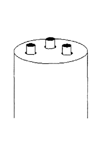
-6.5x10⁷ counts/s (using 2200 V) and a CTMS-treated 54-channel stock MSF
emitter gives a
TIC -9.5x10⁷ counts/s (using 3200 V). For the 2-minute trace in Figure 14, the
relative standard
deviation in signal was 3.8%, indicating very good performance relative to
tapered emitters and
MSF emitters without polymers and etching.
It is expected that etching with HF or another etchant, rather than ammonium
bifluoride,
may produce nozzles with less expansion of the MSF channels diameters (i.e.,
with less loss of
the matrix material surrounding the nozzles (see Figure 12b). This may lead to
increased spray
stability.
Example 3.
In certain applications it is desirable to have a multi-channel electrospray
emitter that can
produce multiple electrosprays (e.g., a distinct Taylor cone produced by each
nozzle). However,
as noted above, in MSF emitters prepared with a flat tip face, the spray from
individual nozzles
may coalesce, detracting from the multiple electrospray (ME) spray effect. In
this example
multiple electrosprays were produced using emitters with smaller numbers of
nozzles.
Emitters were prepared from a two channel pulled glass MSF and one, three, and
nine
channel polycarbonate MSFs. The arrangements of the channels/nozzles in the
three and nine
channel MSFs are shown in Figures 15a and 15b.
Tests were run to measure the spray stability and current of two channel
emitters
prepared from glass MSF, and one, three, and nine channel emitters prepared
from polycarbonate
- 29 -
CA 02715365 2010-09-21
= . MSF. The emitter was placed 2-3 mm from a gold coated wire mesh. A
custom pump
(Upchurch Scientific, Oak Harbor, Washington, U.S.A.) delivered the spray
solvent. A T-
junction was used to apply a voltage in the spray solvent. Voltages spanned
2000V to 4000V,
and the spray solvent was kept constant at a 50:50 mixture of water and
methanol with 1% acetic
acid added as an ion source. Flow rates varied from 30 to 300 nL/min. Emitters
were viewed
and photographed through a Nikon Eclipse Ti-S inverted fluorescence microscope
(Nikon
Canada, Mississauga, ON, Canada). Excitation was provided by an X-Cite Series
120Q light
source (Exfo Photonic Solutions Inc., Quebec City, QC, Canada) with a 450-490
nm excitation
filter provided with the microscope. Images were captured by a Nikon DS
digital camera.
The two channel glass MSF (from Friedrich & Dimmock, Inc., Millville, NJ,
U.S.A.) had
channels of 25 1.trn diameter, and the fibre diameter was 157 gm. The fibre
was pulled under
heat from a propane torch and gravity-assisted force from a 23 g weight. After
pulling, each
channel diameter was about 5 m, and the two channels were spaced about 30 pin
apart.
The two channel glass emitter produced two separate Taylor cones. The two
sprays were
not parallel to the fibre, but pointed away from one another. This was due to
the sprays being
positively charged, therefore repelling each other. Because these emitters
would not fit in
standard fittings due to their large diameter on the non-pulled end, solvent
pumping was done by
hand with a syringe pump. Consequently, the actual flow rate was not known
precisely, but was
approximately 200 nL/min. The applied voltage of 4000V was high for standard
ESI; however,
it was found to be necessary to achieve multiple electrospray. At lower
voltages, the spray
would coalesce into one larger cone, or not form a cone at all. The observed
spray current was
very low and unstable, fluctuating between approximately 3-10 nA. An attempt
to improve these
points was made by treating the emitters for 1 hour or 16 hours in a 20:80
chlorotrimethylsilane
(CTMS):toluene solution, but no gains were observed.
For the polycarbonate emitters, three and nine channel polycarbonate MSFs
(Kiriama Pty
Ltd., Sydney, Australia) were used. The three channel fibre had a diameter of
615 p.m and
channel diameter of 8 to 9 pm. The nine channel fibre had a diameter of 630
p.m and channel
diameter of 9 to 11 pm. For the three channel fibre, the channels were equally
spaced on a 415
p.m diameter about the central axis of the fibre. For the nine channel fibre,
the channels were
equally spaced on a 430 pm diameter about the central axis of the fibre.
Diagrams of the fibre
- 30 -
CA 02715365 2010-09-21
- cross sections are shown in Figures 15a and 15b.
The three and nine channel polycarbonate were able to produce multiple
electrosprays.
The three channel polycarbonate emitter produced three distinct Taylor cones
that were very
stable (-30 minutes), shown in end view in Figure 16, using a voltage of 3500V
to 4000V, and a
flow rate of 50 nL/min +/- 10 nL/min. It was noted that the emitter face
should be dry in order to
achieve ME. A wet emitter face causes the liquid streams to coalesce,
resulting in a single
Taylor cone.
A protocol to achieve ME may be as follows:
= Set pump at desired flow rate
= Turn off voltage
= Dry the end of the MSF emitter with a dabber or compressed air
= Wait until small droplets form around each nozzle, then turn on voltage
Similar experiments were performed on the nine channel polycarbonate emitter,
using a
voltage of 3500V to 4000V and flow rate of about 75nL/min to 150nL/min for
stable ME. Figure
17 shows an end view of the nine channel emitter producing ME. From Figure 17
it can be seen
that the separate Taylor cones did not form directly over the nozzles, but
rather stabilized on the
edge of the fibre. This was due to the fact that each cone is positively
charged, such that the
cones repel each other.
To enhance the ability of the emitters to produce ME, hydrophobicity of the
polycarbonate material was increased. The increased hydrophobicity reduces
wetting of the
emitter face by the spray solvent, so that solvent exiting each nozzle forms a
Taylor cone.
CFI plasma ionization was carried out to increase hydrophobicity of the
polycarbonate.
Investigations were performed on a Harrick PDC-001 plasma ionizer with CF4
(Sigma-Aldrich)
to determine an optimal procedure for surface modification. 2 cm x 2 cm plates
of polycarbonate
cleaned with methanol were subjected to various lengths of ionization at 29.6
W and 400 m Ton.
The contact angle of water as well as the standard solvent solution of 50:50
water:methanol and
1% acetic acid were measured. The contact angle of both water and the spray
mixture increased
asymptotically with an increase in treatment time. Based on these
investigations, the PC MSFs
were treated for 5 minutes to give a spray solvent contact angle improvement
of approximately
-31 -
CA 02715365 2010-09-21
- . 20 , i.e., from 65 to 85 . Further treatment tended to warp the fibre
under the heat of the plasma
chamber.
The CF4-modified fibres exhibited the desired reduction in required spray
voltage, while
optimal flow rates remained the same. Voltages of 1800V to 3000V were found to
be suitable
for the modified fibres. Figure 18 shows an end view of the spray of such a
modified fibre. As
can be seen from Figure 18, an emitter prepared from a modified fibre produces
better defined
Taylor cones, and the cones form over the nozzles from which they are fed.
While the individual
sprays are still repelled from each other, it is to a lesser extent, likely
because the required
applied voltage is considerably lower.
Since ME was reliably obtained with three and nine channel emitters, the
validity of
Smith' s31 v¨n theory, which states that the spray current of ME increases
with the square root of
the number of simultaneous Taylor cones. To obtain an additional data point, a
single channel
PC MSF emitter was prepared by melting closed two of the channels of a three
channel PC MSF
emitter with a hot needle. Performance of the single channel emitter was
verified under a
microscope, wherein there was no bleed-off of solvent around the melted area.
A single set of
conditions under which all three fibres would spray was required in order to
make a comparison
and evaluate the -Cn theory. An acceptable condition was found to be at a
potential of 3000V and
a flow rate of 50nL/min using the standard solvent. Each emitter was set up in
turn in the same
apparatus under these conditions, and a steady flow rate and spray current was
achieved, at
which point a 3 minute trace of spray current was obtained. These data are
presented in Figures
19 and 20. From Figure 20 it can be seen that the spray currents from the one,
three, and nine
channel PC emitters during ME closely conform to the Arn-dependence predicted
by Smith31,
with RSDs less than 1.5% for all emitters.
Further enhancements in performance are achieved using emitters with a small
number of
channels/nozzles (e.g., 3 to 12, or 3 to 20 channels), where the emitters are
modified so as to
elevate the nozzles above the emitter face, as described above (i.e., as in
Figure 11(b)). In
particular, an MSF made from silica-based material (such as glass) is suitable
for such an ME
emitter.
- 32 -
CA 02715365 2010-09-21
. Equivalents
While the invention has been described with respect to illustrative
embodiments thereof,
it will be understood that various changes may be made to the embodiments
without departing
from the scope of the invention. Accordingly, the described embodiments are to
be considered
merely exemplary and the invention is not to be limited thereby.
- 33 -
CA 02715365 2010-09-21
- References
(1) Dole, M.; Mack, L. L.; Hines, R. L.; Mobley, R. C.; Ferguson, L. D.;
Alice, M. B. J.
Chem. Phys. 1968, 49, 2240-2249.
(2) Fenn, J. B.; Mann, M.; Meng, C. K.; Wong, S. F.; Whitehouse, C. M.
Science 1989, 246,
64-71
(3) Yamashita, M.; Fenn, J. B. J. Phys. Chem. 1984, 88, 4451-4459.
(4) Busch, K. L.; Cooks, R. G. Science 1982, 218, 247-254.
(9) Wilm, M.; Mann, M. Anal Chem 1996, 68, 1-8.
(10) Martin, S. E.; Shabanowitz, J.; Hunt, D. F.; Marto, J. A. Anal. Chem.
2000, 72, 4266-
4274.
(1 1 ) Schmidt, A.; Karas, M.; Dulcks, T. J. Am. Soc. Mass Spectrom. 2003, 14,
492-500.
(12) Smith, D. R.; Moy, M. A.; Dolan, A. R.; Wood, T. D. Analyst 2006, 131,
547-555.
(13) Zampronio, C. G.; Giannakopulos, A. E.; Zeller, M.; Bitziou, E.;
Macpherson, J. V.;
Derrick, P. J. Anal. Chem. 2004, 76, 5172-5179.
(17) Kelly, R. T.; Page, J. S.; Tang, K.; Smith, R. D. Anal. Chem. 2007, 79,
4192-4198.
(18) Kelly, R.T.; Page, J.S.; Zhao, R.; Qian, W.J.; Mottaz, H.M.; Tang, K.;
Smith, R.D. Anal.
Chem. 2008, 80, 143-149.
(19) Kim, W.; Guo, M.; Yang, P.; Wang, D. Anal. Chem. 2007, 79, 3703-3707.
(20) Le Gac, S.; Rolando, C.; Arscott, S. J. Am. Soc. Mass Spectrom. 2006, 17,
75-80.
(21) Le Gac, S.; Arscott, S.; Rolando, C. Electrophoresis 2003, 24, 3640-3647.
(22) Tang, K.; Lin, Y.; Matson, D. W.; Kim, T.; Smith, R. D. Anal. Chem. 2001,
73, 1658-
1663.
(23) Koerner, T.; Turck, K.; Brown, L.; Oleschuk, R. D. Anal. Chem. 2004, 76,
6456-6460.
(24) Bedair, M. F.; Oleschuk, R. D. Anal. Chem. 2006, 78, 1130-1138.
(25) Koerner, T.; Xie, R.; Sheng, F.; Oleschuk, R. Anal. Chem. 2007, 79, 3312 -
3319.
(26) Russell, P.S.J. Science, 2003, 299, 358-362.
(27) Sun, Y.; Kwok, Y.C.; Nguyen, N.T. Electrophoresis 2007, 28, 4765-4768.
(28) Kriger, M.S., Cook, K.D., Ramsey, R.S. Durable gold-coated fused silica
capillaries for
- 34 -
CA 02715365 2010-09-21
use in electrospray mass spectrometry. Anal. Chem. 1995, 67, 385-389.
(29) Barnidge, D.R., Nilsson, S., Markides, K.E., Rapp, H., Hjort, K.
Metallized sheathless
electrospray emitters for use in capillary electrophoresis orthogonal time-of-
flight mass
spectrometry. Rapid Commun. Mass Spectrum 1999, 13, 994-1002.
(30) Luo Q., Yue G., Valaskovic G.A., Gu Y., Wu S.-L., Karger B.L. Anal. Chem.
2007, 79,
6174-6181.
(31) Smith, R., Tang, K., Lin, Y., Matson, D., & Kim, T. Generation of
Multiple Electrosprays
Using Microfabricated Emitter Arrays for Improved Mass Spectrometric
Sensitivity.
Analytical Chemistry 2001, 73, 1658-1663.
- 35 -