Note: Descriptions are shown in the official language in which they were submitted.
CA 02716228 2011-07-22
VPI-004
SYSTEM AND METHOD FOR INHIBITING INJURY TO A PATIENT DURING
LAPAROSCOPIC SURGERY
FIELD OF THE INVENTION
[001] The
present invention relates to systems for reducing accidental injury
to patients during surgery and more particularly during laparoscopic surgery.
BACKGROUND OF THE INVENTION
[002] Compared with conventional surgery, laparoscopic surgery is an
excellent means for achieving significant reductions in surgery-related
morbidity.
These reductions are achieved, however, only if the procedure is performed
completely and without effective errors. Unfortunately, error-free
laparoscopic
surgeries are not the rule.
Indeed, intra-operative and post-operative
complications are all too common with laparoscopic surgery procedures.
Because of this, there is a need to improve patient safety during laparoscopic
surgery so that the benefits derived from such procedures are achieved while
the
drawbacks are reduced or eliminated.
[003] One of the most profound drawbacks of laparoscopic surgery is the
occurrence of unintentional or inadvertent injuries to patient tissue
structures
adjacent to or sometimes, distant from the intended surgical site or field. In
the
pelvic cavity, for example, bowels, ureters, large organs and blood vessels
can
be injured either directly from the heat or sharpness of the laparoscopic
instruments, or burned indirectly through the conduction of heat through
nearby
tissues. Typically, such injuries are not appreciated at the time of surgery
because the specific injury sites are hidden by blood or other patient
tissues. As
another disadvantage attendant to such iatrogenic injuries, the response to
the
unintended injury manifested by the patient is often a delayed one. This
delayed
response can be traumatic as well as tragic, and can sometimes result in one
or
more further surgeries, which would otherwise be unnecessary.
[004] The implications from both a medical perspective as well as a medico-
legal perspective are enormous. Obviously, such injuries are negative events
1
CA 02716228 2011-07-22
VP1-004
and therefore best avoided. The present invention is therefore directed to
reducing the occurrence and severity of these negative events.
SUMMARY OF THE INVENTION
[005] In one aspect, the invention defines or denominates a surgical field
as
a three-dimensional space in which the operative portions of laparoscopic
instruments, those portions which are capable of causing harm to the patient
or
medical personnel, are permitted to function. In some embodiments, the
hazardous or dangerous function of the instruments can be automatically
attenuated or eliminated outside of this denominated space. The operative
portions of a laparoscopic instrument or appliance include those that can
potentially cause damage if they contact a patient's tissues in an unintended
manner. Examples of such potentially damaging portions include hot wires,
electrically charged wires, blades, scissors and shears, sharp points or
surfaces.
Thus, the operative portions can include those that are adapted and arranged
to
do one or more of cut, cauterize, ablate, seal, fuse, skewer or clamp.
[006] In another significant aspect, in order to track and monitor the
relative
positions and orientations of the instruments with respect to the protected
space,
and in order to track a probe used to assist in defining the protected space
(ie. a
safe zone) the present invention employs one or more of software, optics, high
speed digital imaging, such as visible spectrum or infrared (IR) imaging, 2D
or 3D
ultra sound, MRI and CAT scan images, visible spectrum or infrared (IR)
imaging,
photography, electromagnetic sensing, radio frequency (RE) sensing as well as
one or more sensors to enable the surgeon, operating room and other medical
personnel, including remote medical personnel, to be apprised of the precise
positional status of the laparoscopic instruments being used.
[007] Positional status refers to the relative position of the operative
and
non-operative portions of the various laparoscopic appliances and tools being
used with respect to various portions of the patient's body, or with respect
to the
denominated surgical field, or with respect to one or more sensors placed
inside
or outside the patient's body.
2
CA 02716228 2011-07-22
VP1-004
[008] A positive positional status refers to circumstances where the
operative
portions of the laparoscopic instruments are within the denominated boundaries
of the surgical field. A neutral positional status refers to circumstances
where the
operative portions of the laparoscopic instruments are in the denominated
surgical field but near at least one boundary. A negative positional status
refers
to circumstances where the operative portions of the laparoscopic instruments
are outside of the denominated surgical field, or within a predetermined
distance
of a sensor.
[009] Positional status is determined with respect to a three-dimensional
surgical field having defined boundaries, or with respect to one or more
sensors
placed in proximity to vulnerable tissues. In accordance with certain aspects
of
the invention, those boundaries can be defined in a number of different ways
and
combinations thereof. For example, in some embodiments, proximity to one or
more sensors placed on a vulnerable organ or tissue defines the boundaries of
the protected space or denominated field. In other embodiments of the
invention,
the boundaries of the field can be determined with respect to distance from an
object, such as a net used for sequestering the bowel, and the like. Thus,
definition of the various boundaries makes it possible to determine the
relative
positions of various portions of laparoscopic instruments with respect to the
denominated surgical field, and with respect to vulnerable tissues and organs,
as
well as with respect to various medical personnel.
[0010] Thus, in accordance with an embodiment of the invention, the
three-
dimensional spatial boundaries of a surgical field can be determined, or
denominated, in a number of different ways. The present means and methods
thus denominate the shape and volume of a three-dimensional space, and also
track the position of portions of various instruments with respect to that
space.
By doing so, the likelihood of inadvertent damage is decreased. This is
further
enhanced by other aspects of the invention.
[0011] For example, each laparoscopic instrument being used in a
particular
procedure can have a range of statuses. Each of these statuses can be
determined by the instrument's relative position in the denominated field, for
3
CA 02716228 2011-07-22
VPI-004
example, by means of distance sensors, magnetic sensors, heat sensors,
proximity sensors, 2D or 3D imaging technologies (Ultra-sound, MRI, etc.) and
the like.
[0012] Thus, a system of the present invention "knows" where inside the
body
the operative portions of the laparoscopic instruments are located at all
times.
The sensors therefore aid the surgeon in staying away from vulnerable tissues
and areas within the patient's body. Moreover, the instruments can be in
operative communication, programmed or coded to shut off in the event that a
dangerous structure is within the radius of a direct injury or a thermal burn,
for
instance. In an embodiment the invention reduces morbidity by providing the
surgeon and other medical personnel with a "denominated surgical field" or
"protected space" within which to perform the indicated procedure while
reducing
the risk of damage to other organs which, in essence, are provided with a kind
of
"force field" around them. Thus, in one aspect, the means and methods of the
invention function to sequester vulnerable portions of the patient's body.
[0013] When the borders or limits of the denominated field are breached
are
approached, the system provides also for warnings to be given, such as a buzz
or handle vibration in the laparoscopic tool being used. A system in
accordance
with an embodiment of the invention can thus be adapted and arranged such that
the energized or sharp portions of the appliance are operational only within
the
boundaries determined by the sensor-enabled laparoscopic field, that is, the
denominated field. As an example, in some embodiments, the means and
methods of the invention can be adapted and arranged such that the sharp
edges of the appliance are automatically withdrawn into one or more sheaths
provided as part of the laparoscopic appliance.
[0014] In other embodiments of the invention, the means and methods of
the
invention can be effected by way of software that controls the various energy
inputs to the laparoscopic instruments being used, thus preventing the
unwanted
cutting, avulsing, cauterizing, ablating, or severing of a patient's tissues
and
organs.
[0015] As yet another advantage, the means and methods of the present
4
CA 02716228 2011-07-22
VPI-004
invention can also be adapted and arranged as teaching tools for providing
virtually instantaneous feedback to surgeons and other medical personnel
regarding their abilities and techniques in laparoscopic surgery. Various
feedback loops and sensitivities of the invention can be adjusted to provide
tailored instruction with respect to instructional or experimental surgeries
on
animals or models.
[0016] In some embodiments, all points, co-ordinates, positions and
movements of instruments, body, organs and tissues can be recorded and stored
for later playback if necessary. The playback can be provided in any of the
following formats: audio, graphs, 20 graphic, and 3D graphic, or in any
combination thereof.
[0017] In another aspect, the invention is directed to a surgical system
for use
on a body of a patient, wherein the system permits the user to determine the
positions of a plurality of points on internal body portions of the patient
surrounding a surgical field, wherein the points are used by a controller to
determine a safe zone in which a functional element on a surgical instrument
can
be positioned without causing injury to the patient. The positions of the
points
may be monitored by the controller in real time so that if, after the safe
zone is
determined initially by the controller, the internal body portions of the
patient
move, the controller updates the data relating to the safe zone in real time.
The
system uses a sensor net that is positioned in the surgical field to assist in
determining the points that define the safe zone both initially and in real
time
during a medical procedure.
[0018] In another aspect, the invention is directed to a method of using
a
surgical system on a body of a patient. The method is used to determine the
positions of a plurality of points on internal body portions of the patient
surrounding a surgical field, in order to determine a safe zone in which a
functional element on a surgical instrument can be positioned without causing
injury to the patient. The positions of the points may be updated in real time
during a medical procedure so that if the internal body portions of the
patient
move after the safe zone is determined initially, the data relating to the
position of
5
CA 02716228 2011-07-22
VPI-004
the safe zone can be updated in real time. The method incorporates the use of
a
sensor net that is positioned in the surgical field to assist in the
determining of the
points that define the safe zone both initially and in real time during a
medical
procedure.
BRIEF DESCRIPTION OF THE DRAWINGS
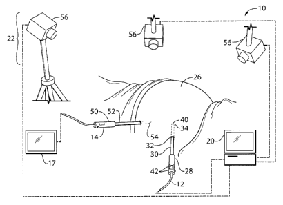
[0019] Figure 1 is a perspective view of a surgical system for use on
the body
of a patient in accordance with an embodiment of the present invention;
[0020] Figures 2a-2d illustrate the surgical system shown in Figure 1
being
used to determine a safe zone within the patient in which a surgical
instrument
can be maneuvered without causing injury to the patient;
[0021] Figure 2e is a perspective view of a surgical instrument being
used
during a surgical procedure;
[0022] Figure 3 is a perspective view of an optional net that can be
included
with the system shown in Figure 1;
[0023] Figures 4a-4d are examples of markers that can be included on a
probe shown in Figure 1 to permit tracking of the probe by a camera system;
[0024] Figure 5 is a magnified perspective view of the net shown in
Figure 3
[0025] Figures 6a-6a are examples of markers that can be included on a
surgical instrument shown in Figure 1 to permit tracking of the surgical
instrument
by a camera system; and
[0026] Figure 7 is an alternative probe for use with the system shown in
Figure 1; and
[0027] Figures 8a and 8b are a flow diagram of the programming for a
controller in the surgical system shown in Figure 1.
DETAILED DESCRIPTION OF THE INVENTION
[0028] Reference is made to Figure 1 which shows a surgical system 10
for
use on a body of a patient in accordance with an embodiment of the invention.
The surgical system 10 includes a probe 12, a laparoscope 14, a surgical
instrument 16 (Figure 3), a display 17, netting 18 (Figure 3) with a plurality
of
6
CA 02716228 2011-07-22
VPI-004
safe zone definition sensors 19 on it, a controller 20 and a tracking system
22,
which in the embodiment shown is a camera system. The surgical system 10 is
configured to reduce the incidence of injuries to patients during laparoscopic
surgery.
[0029] The system 10 is initially used to determine a safe zone 24 (Figure
2e)
within the patient shown at 26 (only a portion of the patient 26 is shown in
Figure
1) in which the surgical instrument 16 can be maneuvered without causing
injury
to the patient 26. The determination of the safe zone 24 involves the probe
12,
the laparoscope 14 in particular. The probe 12 includes a probe body 28 and an
interior portion 30 connected to the probe body 28. The interior portion 30 is
configured to be at least partially inserted into the body of the patient 26
through
one of a plurality of apertures 32 made in the body of the patient 26. The
particular aperture 32 through which the probe 12 is inserted is shown at 32a.
The interior portion 30 is therefore made from a material that will not cause
harm
to the patient, such as, for example, a suitable stainless steel. The probe
body 28
is configured to be outside the body of the patient 26 during use.
[0030] The probe 12 further includes a probing portion 34 on the
interior
portion 30. The probing portion 34 is a portion of the interior portion 30 and
is
used to identify the positions of points on the internal body portions shown
at 36
(Figure 3) of the patient 26 that are in the surgical field (ie. that are in
the vicinity
of the particular site in the patient 26 that requires surgery). The surgical
field is
shown in Figure 3 at 38. Referring to Figure 2a, the probing portion 34 may be
at
a tip 40 of the interior portion 30. The probing portion 34 may have one or
more
selected properties which may be different from the rest of the interior
portion 30
so that other portions of the interior portion 30 cannot be mistaken by the
system
10 as being the probing portion 34. For example, the probing portion 34 may be
configured to be magnetic. Alternatively, the probing portion 34 may be
configured to be electrically conductive. Alternatively, the probing portion
34 may
be heated to a selected temperature. Alternatively, the probing portion 34 may
be configured to emit signals at a selected frequency and strength.
Alternatively,
the probing portion 34 may simply be of the same material as the rest of the
7
CA 02716228 2011-07-22
=
VP1-004
interior portion 30, and may simply be conveniently shaped so as to permit
easy
pointing at an object (eg. an internal body portion 36).
[0031]
During use of the probe 12 it is desired for the controller 20 to be able
to determine the position of the probing portion 34 at selected times. To this
end,
a probe marker 42 is provided on the probe body 28. The probe marker 42 is,
during use, viewed by the camera system 22 and is used by the controller 20 to
identify the probe 12 (ie. to distinguish the probe 12 over other objects,
such as
the instrument 16).
Additionally or alternatively, the probe marker 42 is
configured to provide sufficient information to the controller 20 for the
controller
20 to be able to determine the position and orientation of the probe marker
34.
By determining the position and orientation of the probe marker 34, the
controller
can determine the position and orientation of the probe 12 itself and
therefore
can determine the position of the probing portion 34. Determining the position
of
the probing portion 34 is used by the controller 12 in determining where the
15 internal body portions 36 of the patient 26 are, which is then used by
the
controller 20 to determine the safe zone 24.
[0032] As shown in Figure 6a the probe marker 42 may, for example, be
made up of a plurality of LEDs 44 on the probe 12. Some aspect of the LEDs 44
is unique so as to facilitate detection of the probe marker 42 in the images
sent
20 by the camera system 22 to the controller 20 and optionally to
distinguish the
probe marker 42 from an analogous marker on the surgical instrument 16. For
example, the arrangement of the LEDs 44 on the probe body 28 may be
distinguishable by the controller 20 to detect the probe marker 42 and
optionally
to identify it as the probe marker 42 as opposed to the aforementioned marker
on
the surgical instrument. Alternatively or additionally, the LEDs 44 may be
configured to emit light at a particular wavelength or combination of
wavelengths
of light.
[0033] The
LEDs 44 may be configured to emit light at a non-visible
wavelength (eg. infrared) so as to not distract the user of the probe 12 (eg.
the
surgeon) during use.
[0034] As an alternative to LEDs, the probe marker 42 may be made up of
8
CA 02716228 2016-11-30
VPI-005
DESCRIPTION
any suitable means for identifying the probe 12 and for identifying the
position
and orientation of the probe 12. For example, the probe marker 42 may include
one or more symbols 47a (eg. polygons) on a suitable background 47b as shown
in Figure 6b. The colour of the symbols 47a and the colour of the background
47b may be selected to be of sufficient contrast to facilitate locating the
symbols
on the background, and may be selected to be sufficiently unique so as to
permit
the controller 20 to detect the probe marker 42 in the images provided by the
camera system 22. Alternatively, as shown in Figure 6c, a combination of LEDs
44 and symbols 47a and a background 47b may be provided. As shown in
Figure 6d, the probe marker 42 may be removable from the probe body 28. For
example, the marker 42 may be provided on a sleeve.
[0035] The netting 18 may have several purposes. For example, the
netting
18 may be positionable to restrain at least some of the internal body portions
36
in the surgical field 38 from obstructing the surgical instrument 16 when the
surgical instrument 16 is being used in the surgical field 38. Alternatively,
the
netting 18 may simply be provided to conform to the shape of at least some of
the internal body portions 36 in the surgical field 38. The netting 18 may be
provided with any suitable means for restraining the internal body portions
36.
For example, the netting 18 may be provided with a plurality of hold down
members 46 which extend out of the body of the patient 26 and which may be
attached to suitable attachment points on a support frame (not shown).
Alternatively, the netting 18 may be provided with one or more hold down
members that connect to other points within the body of the patient 26.
Alternatively, the netting 18 may be provided with a grippy, elastic
peripheral
edge permitting the netting 18 to be mounted over internal body portions 36
and
to hold on to the body portions 36 themselves. The netting 18 may be made up
of one or more individual nets each of which is affixed to internal body
portions
36 around the surgical field 38.
[0036] The plurality of safe zone definition sensors 19 on the netting
18 are
configured to communicate with the controller 20 and to cooperate with the
probe
12 to establish the positions of points on at least some internal body
portions 36
9
CA 02716228 2011-07-22
VPI-004
in the surgical field 38 to assist in the determination of the safe zone 24 by
the
controller 20. The safe zone definition sensors 19 may be any suitable type of
sensors, such as, for example, electromagnetic (EM) sensors, magnetic sensors,
heat sensors, radio frequency (RF) sensors, proximity sensors, GPS, Hall
Effect
sensors and any other suitable type of sensor. Each safe zone definition
sensor
19 is configured to detect when the probing portion 34 is at a selected
proximity
to it.
[0037] In an exemplary embodiment, each safe zone definition sensor 19
is
configured to detect when it is contacted by the probing portion 34. For
example,
the sensor 19 may be configured to detect self-movement, which would take
place when contacted by the probing portion 34. Alternatively or additionally
the
sensor 19 may determine contact by the probing portion 34 by some other
means. For example, contact with the probing portion 34 may close an
electrical
circuit through the sensor 19, which could be used to send a signal to the
controller 20 that contact is made with the probe 12.
[0038] Each sensor 19 may include an accelerometer that is capable of
detecting self-movement in three dimensions. When detecting self-movement,
the sensor 19 is configured to communicate the amount of self-movement to the
controller 20 so that the controller 20 can update the position of the sensor
19 in
real time. Because the position of the sensors 19 indicates the position of
the
internal body portions 36 of the patient 26, the controller 20 can thus
determine if
the internal body portions 36 move during surgery, and can use this
information
to continuously determine a new safe zone 24 (Figure 2e) in real time during
surgery.
[0039] The sensors 19 may communicate with the controller 20 via any
suitable means. For example, an electrical conduit 48 (Figure 3) may extend
from the sensors 19 out of the body of the patient 26 to the controller 20.
[0040] The laparoscope 14 includes a laparoscope body 50 and an interior
portion 52 connected to the laparoscope body 50. The interior portion 52 is
configured to be at least partially inserted into the body of the patient 26
through
one of the apertures 32. The particular aperture 32 through which the probe 12
CA 02716228 2011-07-22
VP1-004
is inserted is shown at 32b. The interior portion 52 is therefore made from a
material that will not cause harm to the patient, such as, for example, a
suitable
stainless steel. The laparoscope body 50 is configured to be outside the body
of
the patient 26 during use.
[0041] The interior portion 52 includes an image receiving element 54.
During
use, the image receiving element 54 is positionable in the surgical field 38
in the
body of the patient 26 to receive images of the probing portion 34 when the
image receiving element 54 is in the surgical field 38. The image receiving
element 54 may be a lens, for example. The laparoscope 14 is configured by
any suitable means to transmit received images to the display 17. For example,
the laparoscope 14 may include an image sensor (not shown), which may be, for
example, a CCD sensor or a CMOS sensor, that is positioned to receive images
from the image receiving element 54. The laparoscope 14 is configured to
transmit the images of the probing portion 34 to the display 17 (optionally
via a
controller such as the controller 20).
[0042] The surgical instrument 16 includes an instrument body 90 and an
interior portion 92 connected to the instrument body 90. The interior portion
92 is
configured to be at least partially inserted into the body of the patient 26
during
use. The instrument body is configured to be outside the body of the patient
during use. The interior portion 92 includes a functional element 94, which is
an
element that is configured to perform a particular function on the patient.
For
example, the functional element 94 may be a cutting blade, a scissors
mechanism or for example a heating element to cauterize. As will be
understood,
the functional element 94 may cause unintended injury to the patient 26 if it
is
accidentally brought into contact with the internal body portions 36 of the
patient
26 surrounding the surgical field 38.
[0043] During use of the surgical instrument 16 it is desired for the
controller
20 to be able to determine the position of the functional element 94
substantially
continuously. To this end, an instrument marker 96 is provided on the
instrument
body 90. The instrument marker 96 is, during use, viewed by the camera system
22 and may be used by the controller 20 to identify the surgical instrument 16
(le.
11
CA 02716228 2011-07-22
=
VPI-004
to distinguish the surgical instrument 16 over other objects, such as the
probe
12). Additionally or alternatively, the instrument marker 96 is configured to
provide sufficient information to the controller 20 for the controller 20 to
be able to
determine the position and orientation of the instrument 16. By determining
the
position and orientation of the instrument marker 96, the controller 20 can
determine the position and orientation of the surgical instrument 16 itself
and
therefore can determine the position of the functional element 94. Determining
the position of the functional element 94 is used by the controller 12 in
determining whether the functional element 94 is within the safe zone 24.
[0044] Some examples of instrument markers 96 are shown in Figures 4a, 4b,
4c and 4d. The instrument marker 96 may includes LEDs 44 (Figure 4a), one or
more symbols 47a (eg. polygons) on a suitable background 47b (Figure 4b), or a
combination of the two (Figure 4c). The instrument marker 96 may be removable
from the instrument body 90 as shown in Figure 4d. For example it may be
provided on a sleeve.
[0045] The camera system 22 includes at least one camera 56 and preferably
includes a plurality of cameras 56 mounted around the surgical theatre. The
cameras 56 are positioned at selected positions to reduce the likelihood of
obstruction of their view of the probe marker 42 and the instrument marker 96.
The cameras 56 receive images of the probe marker 42 and transmit the images
to the controller 20. The controller 20 is programmed to locate the probe
marker
42 in the images and to determine by any suitable means, the position and
orientation of the probe 12 and therefore the position of the probing portion
34.
This may be achieved by comparing the images from two or more cameras 56
and using triangulation. Alternatively, a stereoscopic camera 56 may be used,
so
as to provide three-dimensional position information through images sent to
the
controller 20 without using multiple cameras. Alternatively, a single non-
stereoscopic camera 56 may be used which sends a non-stereoscopic image to
the controller 20. The controller 20 can determine easily the position of the
marker 42 in the two dimensional plane of the image easily and the depth of
the
probe marker 42 (ie. its distance from the camera along a third dimensional
axis
12
CA 02716228 2011-07-22
VPI-004
perpendicular to the plane of the image) may be determined based on the
apparent size of the marker 42 in the image.
[0046] Providing two or more cameras 56 may be advantageous to reduce the
likelihood of the surgeon's hands or body from preventing the camera system 22
from obtaining an unobstructed view of the probe marker 42. In an embodiment
where at least two cameras 56 are required to have an unobstructed view of the
marker 42, the camera system 22 preferably includes 3 or more cameras 56.
[0047] Instead of incorporating cameras, the tracking system 22 could
alternatively incorporate other types of tracking system sensor that is
configured
to sense the position of the probe marker and the instrument marker. For
example, the tracking system could incorporate one or more of the following
exemplary techniques to sense the position of the instrument 16 and of the
probe
12: 2D or 3D ultra sound, MRI and CAT scan images, electromagnetic sensing,
radio frequency (RF) sensing. Regardless of the technique used, and the
technology used, whatever is on the probe and on the instrument that is
detected
by the tracking system may be considered a probe marker and an instrument
marker respectively.
[0048] The operation of determining the safe zone 24 is as follows, with
reference to Figures 1-6 and with reference to the flow diagram 200 shown in
Figures 8a and 8b. Initially, a probe, a surgical instrument, a laparoscope, a
tracking system, and netting with the sensors 19 therein are provided in steps
202, 204, 206, 208 and 210 (Figure 8a). Then a plurality of points 58 on
internal
body portions 36 that surround the surgical field 38 are determined. To do
this,
the user creates the apertures 32. The user inserts the netting 18 with the
sensors 19 thereon into the surgical field 38 through one of the apertures 32
and
affixes the netting 18 as desired. The user inserts the laparoscope 14 into
the
surgical field 38. The user inserts the probe 12 into the surgical field 38.
The
camera system 22 receives images of the probe marker 42 and transmits the
images to the controller 20 (the images thus constitute probe marker input).
The
user can see the probing portion 34 of the probe 12 on the display 17 via the
transmission of images from the laparoscope 14 to the display 17. Using the
13
CA 02716228 2011-07-22
VP1-004
images from the laparoscope 14 the user guides the probe 12 so that the
probing
portion 34 contacts a first of the safe zone identification sensors shown at
19a.
When the first sensor 19a senses contact with the probing portion 34, the
first
sensor 19a indicates the occurrence of the contact to the controller 20 (step
212).
In this particular example, the first point 58a on the internal body portions
36 is
substantially immediately adjacent the probing portion 34, since they are
separated only by the sensor 19a, which may be thin. When the controller 20
receives the indication from the first sensor 19a that contact was made, the
controller 20 determines the position of the probing portion 34 of the probe
12
(step 214) based on the one or more images that were received from the camera
system 22 at the time that the indication of contact from the sensor 19a was
sent.
The indication of the contact with the first sensor 19a, in combination with
the
one or more images from the camera system 22 may be considered input
indicating the position of a first point 58a on the internal body portion 36.
The
controller 20 may use any suitable method for determining the position of the
probing portion 34. The controller 20 uses the one or more images to determine
the position and orientation of the probe marker 42, and thus the probe 12.
The
method used for this determination depends on whether the camera system 22
provides a single non-stereoscopic image, a plurality of non-stereoscopic
images,
or one or more stereoscopic images. It will be understood by one skilled in
the
art however, that many suitable algorithms exist for the determination of the
position and orientation of an object using one or more images.
[0049] Once the controller 20 has determined the position and
orientation of
the probe 12, the controller 20 can then determine the position of the probing
portion 34 based on the distance between a selected portion of the probe
marker
42 and the probing portion 34 (which is a known value that is stored in the
controller's memory). Using the position of the probing portion 34, the
controller
20 can determine the position of the safe zone definition sensor 19a, and thus
the position of point 58a (step 216). In this example, because the sensor 19a
is
substantially immediately adjacent the probing portion 34 and is thin, the
determined position of the point 58a on the internal body portions 36 may be
14
CA 02716228 2011-07-22
VP1-004
considered to be the same as the position of the probing portion 34. Once the
position of the point 58a on the internal body portions 36 is determined, the
controller 20 records it for use in determining the safe zone 24. After
contacting
the first sensor 19a, the user guides the probe 12 using the laparoscope 14
and
display 17 so that the probing portion 34 contacts a second sensor 19b for the
purpose of having the controller 20 determine the position of a second point
58b
on the internal body portions 36. The user continues to go from sensor 19 to
sensor 19 until all the sensors 19 have been contacted. In the flow diagram
200
this is shown by the controller 20 checking at step 218 if indications have
been
received from all the sensors 19 and sending program control back to prior to
step 212 if the answer to the check step 218 is 'no'.
[0050] While one particular sensor 19 was referred to in this example as
the
first sensor 19a, it will be understood that any of the sensors 19 could have
been
referred to as the first sensor 19a, and any of the sensors 19 could have been
referred to as sensor 19b, and so on.
[0051] Once the positions of the points 58 corresponding to the
positions of
the sensors 19 have been identified, (ie. the answer to check step 218 is
'yes')
the controller 20 determines the safe zone 24 based on the points 58 (step
220).
The points 58 may thus be referred to as safe zone defining points. The safe
zone 24 may be determined by generating a plurality of virtual surfaces shown
at
60 in Figure 2d between the points 58. The controller 20 may generate the
virtual surfaces 60 between groups of points 58, as shown in Figure 2d. The
surfaces 60 may, for example, be quadrilateral surfaces between groups of 4
points 58, or may be triangular surfaces between groups of 3 points 58, or may
be surfaces having some other number of sides between correspondingly sized
groups of points 58. The virtual surfaces 60 define the periphery of the safe
zone
24, which can be considered to be a virtual conduit through which the
functional
element 94 of the instrument 16 can pass without causing injury to the patient
26.
[0052] In addition to determining points 58 based on the positions of
the
sensors 19, the probe 12 may be used to determine some points 58 that are not
based on the sensors 19. For example, the probe 12 may be positioned with the
CA 02716228 2011-07-22
VP1-004
aid of the laparoscope 14 so that the probing portion 34 contacts the tip of a
bone.
When in contact with the bone, the user may indicate to the controller 20 to
determine the position of the probing portion 34. For example, the probe 12
may
include a button 103 as shown in Figure 7, which the user can press to
indicate
to the controller 20 to determine the position of the probing portion 34.
[0053] Once the points 58 have been determined, they may be stored in a
database as shown at step 221. After the positions of the points 58 have been
determined, the probe 12 may be removed from the patient 26.
[0054] The surgical instrument 16 is then used on the patient to carry
out
some task, such as cutting, cauterizing or some other suitable task. During
use
of the surgical instrument 16, it is possible that the internal organs of the
patient
may move. If the internal body portions 36 move during surgery it is important
that the determined safe zone 24 be updated so as to continue to be useful in
preventing inadvertent injury to the patient 26. In order to provide this
capability,
the sensor 19 associated with each point 58 is capable of sensing self-
movement,
and indicates to the controller 20 the amount of movement it has incurred in
three
dimensions. By having the sensors 19 indicate their movement to the controller
20, the controller 20 can update the positions of the associated safe zone
defining points 58 relating to the moved sensors 19 and can update the
surfaces
60 that define the safe zone 24. In this way, the safe zone 24 can be updated
continuously so that the functional element 94 is prevented from injuring the
patient 26 even if the internal body portions 36 of the patient 26 move after
the
safe zone 24 has been initially determined. This is represented as step 222 in
Figure 8b. At step 223, the updated points are also stored in the database.
[0055] Any points 58 that were determined without the use of associated
sensors 19 cannot be updated as described above, since there are no
associated sensors 19 to sense movement of the point 58. Instead, these points
58 may be considered by the controller 20 to be fixed (le. non-moving during
the
course of the medical procedure). Preferably any such points are points that
are
not expected to move during the medical procedure, such as points on certain
bones.
16
CA 02716228 2011-07-22
VP1-004
[0056] During use of the surgical instrument 16, the camera system 22
receives images of the instrument marker 96 and sends the images (which may
be referred to as instrument marker input) to the controller 20 (step 224).
The
controller 20 processes the input using a similar algorithm to that used for
determining the position of the probing portion 34, to determine the position
of
the functional element 94 (step 226). This information is used to determine
whether the functional element 94 is within the safe zone 24 (step 228). If
the
functional element 94 is outside the safe zone 24 (ie. the answer to check
step
228 is `no'), the controller 20 is programmed to carry out at least one action
selected from the group of actions consisting of: notifying the user of the
surgical
instrument 16 that the functional element 94 is outside the safe zone 24; and
disabling the functional element 94 (step 230).
[0057] Disabling the functional element 94 may be carried out in a
number of
ways depending on what makes up the functional element 94. For example, if
the functional element 94 is a heating element, power may be cut to it.
Alternatively, if the functional element 94 includes a sharp edge (eg. a
cutting
blade), the instrument 16 may include a sheath, and may be configured to
automatically cover the functional element 94 with the sheath.
[0058] The controller 20 may notify the user in any suitable way that
the
functional element 94 is outside the safe zone 24. For example, the controller
20
may be configured to generate a selected sound via a speaker, and/or may be
configured to generate a selected image on the display 17.
[0059] If the functional element 94 is within the safe zone 24 (ie. the
answer at
check step 228 is 'yes'), the controller 20 sends program control to step 232,
wherein it checks if the medical procedure has been completed. This may be
indicated by the user pressing a power button or some other control to let the
system know to stop. If the procedure is over (ie. the answer to check step
232
is 'yes'), then the program (and thus the method) ends. If the answer to the
check step 232 is 'no', then the controller 20 continues to check and update
the
safe zone 24 as mentioned above at step 222 and to continue to receive
instrument marker input at step 224.
17
CA 02716228 2011-07-22
VPI-004
[0060] The controller 20 may be programmed to divide the safe zone 24
(Figure 2e) into two or more sub-zones. For example, the safe zone 24 may be
divided into a safest zone 98 and a danger zone 100. The safest zone 98 is a
central portion of the safe zone 24. If the functional element 94 is kept
within the
safest zone 98 there is a reduced risk that the user will accidentally move
the
instrument 16 in such a way as to cause the functional element 94 to contact
and
cause injury to an internal body portion 36. The danger zone 100 is a
peripheral
portion of the safe zone 24. In other words it is the portion of the safe zone
24
immediately inwardly adjacent to the virtual surfaces 60 that define the
periphery
of the safe zone 24. With the safe zone 24 thus divided into multiple sub-
zones,
the controller 20 may be configured to notify the user via sound and/or images
on
the display 17 whether the functional element 94 is in a relatively safer part
of the
safe zone 24 (eg. the safest zone 98) or is in a relatively less safe part of
the safe
zone 24 (eg. the danger zone 100). For example, a green bar may be displayed
on the display 17 when the functional element 94 is within the safest zone 98,
a
yellow bar may be displayed on the display 17 when the functional element 94
is
within the danger zone 100, and a red bar may be displayed when the functional
element 94 is outside of the safe zone 24. In another embodiment, the
controller
may be programmed to give the user a continuously changing indication of
20 the distance of the functional element 94 from the periphery of the safe
zone 24,
via sound and/or images. For example, the controller 20 may be programmed to
emit sound elements (eg. beeps) at a selected frequency of emissions (eg. 2
beeps per second) if the functional element 94 is relatively far from the
periphery
of the safe zone 24. If the functional element 94 moves closer to the
periphery of
the safe zone 24, the frequency of the beeps may gradually increase (eg. up
to,
for example, 5 beeps per second). If the element 94 leaves the safe zone 24,
the
sound may become continuous.
[0061] After the surgical procedure is completed, the instrument 16, the
laparoscope 14 and the netting 18 may be removed from the patient 26.
[0062] It will be understood that, while it is convenient to have the
sensors 19
on the netting 18, it is alternatively possible for at least some of the
sensors 19 to
18
CA 02716228 2011-07-22
VPI-004
be provided without netting 18. These sensors 19 could be inserted
individually
through an aperture 32 an applied directly to an internal body portion 36
using,
for example, a mild adhesive. It will also be understood that the netting 18
may
be provided without sensors 19 on it. The netting 18 in such an instance can
still
be useful to assist in restraining internal body portions from obstructing the
surgical instrument 16.
[0063] The controller 20 may be configured to record the movements of the
surgical instrument and the data relating to the safe zone 24 (le. the
positions of
the safe zone defining points 58 throughout the medical procedure). The
recording may be made a printed recording, or in a more preferred embodiment,
the recording may be made as data written to a database stored on a computer
readable medium, such as a flash memory so that the surgical procedure can be
played back and reviewed. Instead of a database, the data could be stored in
some other computer readable format such as a data file containing a simple
list.
The capability to play back and review the movements of the instrument and the
safe zone in a medical procedure can be useful to for a variety of purposes.
For
example, the procedure can be reviewed and explained to students in order to
train them in the safe carrying out of such a procedure. Also, in the event
that
there is a complication during the recovery of the patient, the procedure can
be
reviewed to ensure that there was no injury that occurred that is the source
of the
complication.
[0064] The recording of the data and the movements of the instrument can be
provided in any suitable format, such as, for example, audio, graphs, 2D
graphic,
and 3D graphic, or some combination thereof.
[0065] Throughout this disclosure, the components, such as the cameras, the
laparoscope, the safe zone definition sensors and the probe have been shown
and described as communicating with the controller via suitable electrical
conduits such as wires. It will be understood that it is alternatively
possible for
any of these components to communicate with the controller via wireless means,
such as a Bluetooth connection.
[0066] It has been disclosed that the instrument marker 96 and the probe
19
CA 02716228 2011-07-22
VPI-004
marker 42 be used to identify the instrument 16 and the probe 12 to the
controller
20, (ie, to distinguish each from each other and from any other components
sensed by the controller 20). However, an element that is separate from the
marker 42 or 96 could alternatively be provided on the instrument 16 and the
probe 12 respectively to identify each to the controller 20. For example, a
unique
RFID tag can be provided on each to identify each to the controller 20.
[0067] While the above description constitutes a plurality of
embodiments of
the present invention, it will be appreciated that the present invention is
susceptible to further modification and change without departing from the fair
meaning of the accompanying claims.