Note: Descriptions are shown in the official language in which they were submitted.
CA 02719872 2010-09-28
WO 2009/123884 PCT/US2009/038034
ORTHOPAEDIC IMPLANTS HAVING SELF-LUBRICATED ARTICULATING
SURFACES DESIGNED TO REDUCE WEAR, CORROSION, AND ION
LEACHING
CROSS REFERENCE TO RELATED APPLICATIONS
[0001] This application is a Continuation-in-Part of and claims priority to
U.S.
Patent Application Serial No. 11/042,150, filed on January 26, 2005, titled
"TREATMENT PROCESS FOR IMPROVING THE MECHANICAL, CATALYTIC,
CHEMICAL, AND BIOLOGICAL ACTIVITY OF SURFACES, AND ARTICLES
TREATED THEREWITH," which claims priority to U.S. Provisional Application
Serial
No. 60/539,996, filed on January 30, 2004, titled "TREATMENT PROCESS FOR
IMPROVING THE MECHANICAL, CATALYTIC, CHEMICAL, AND BIOLOGICAL
ACTIVITY OF SURFACES, AND ARTICLES TREATED THEREWITH," the
disclosures of which are incorporated herein by reference in their entireties.
FIELD OF THE INVENTION
[0002] The present invention relates generally to orthopaedic medicine. More
particularly, the present invention relates to an orthopaedic medicine where
natural
articulating joints such as knees, hips, shoulders, elbows, wrists, ankles,
fingers and spinal
elements are replaced by implanted mechanical devices to restore diseased or
injured
skeletal tissue.
BACKGROUND OF THE INVENTION
[0003] When mechanical devices such as prosthetic knees, hips, shoulders,
fingers,
elbows, wrists, ankles, fingers and spinal elements are implanted in the body
and used as
articulating elements they are subjected to wear and corrosion. These
prosthetic
(orthopaedic) implants are usually fabricated in modular form with the
individual elements
manufactured from metallic materials such as stainless steels, Co-Cr-Mo
alloys, Zr alloys,
1
SUBSTITUTE SHEET (RULE 26)
CA 02719872 2010-09-28
WO 2009/123884 PCT/US2009/038034
and Ti alloys (Ti-Al-V); plastics such as ultra high molecular weight
polyethylene
(UHMWPE); or ceramics such as alumina and zirconia.
[0004] As the articulating surfaces of these orthopaedic implants wear and
corrode,
products including polyethylene wear particles, metallic wear particles, and
metallic ions
are typically released into the body. Thereafter, these wear particles may be
transported to
and absorbed into bone, blood, lymphatic tissue, and other organ systems. In
general, these
wear particles have adverse effects. For example, the polyethylene wear
particles have
been shown to produce long-term bone loss and loosening of the implant. In
addition, even
very low concentrations of metallic wear particles and metallic ions may have
adverse
immunologic tissue reactions. Accordingly, it is desirable to provide an
orthopaedic
implant that is capable of overcoming the disadvantages described herein at
least to some
extent.
SUMMARY OF THE INVENTION
[0005] The foregoing needs are met, to a great extent, by the present
invention,
wherein in one aspect an orthopaedic implant is provided that in some
embodiments
provides reduced wear and increased fracture and fatigue resistance in
comparison with
some existing orthopaedic implants.
[0006] An embodiment of the present invention pertains to an orthopaedic
implant.
The orthopaedic implant includes a substrate, nanotextured surface, alloyed
case layer, and
conformal coating. The nanotextured surface is disposed upon the substrate.
The
nanotextured surface includes a plurality of bio-active sites. The alloyed
case layer is
ballistically imbedded on to and below the nanotextured surface. The conformal
coating is
disposed upon the alloyed case layer. The nanotextured surface, alloyed case
layer, and the
conformal coating are generated in the presence of a continuous vacuum.
[0007] Another embodiment of the present invention relates to an orthopaedic
implant. The orthopaedic implant includes a first component and second
component. The
first component has a first component surface and the second component has a
second
2
SUBSTITUTE SHEET (RULE 26)
CA 02719872 2010-09-28
WO 2009/123884 PCT/US2009/038034
component surface. The first component and the second component are configured
to
replace a joint in a patient and the first component surface and the second
component
surface are configured to mate at an interface. Both the first component and
the second
component include a substrate, nanotextured surface, alloyed case layer, and
conformal
coating. The nanotextured surface is disposed upon the substrate. The
nanotextured
surface includes a plurality of bio-active sites. The alloyed case layer is
ballistically
imbedded on to and below the nanotextured surface. The conformal coating is
disposed
upon the alloyed case layer. The nanotextured surface, alloyed case layer, and
the
conformal coating are generated in the presence of a continuous vacuum.
[0008] Yet another embodiment of the present invention pertains to a method of
coating a surface of an orthopaedic implant component. In this method, the
component is
placed into a vacuum chamber. The component has a substrate that is textured
to create a
nanotextured surface with a plurality of bio-active sites. The bio-active
sites are configured
to retain a lubricating layer in response to exposure to a bodily fluid and
the texturing is
accomplished by ion beam sputtering the substrate. In addition, the
nanotextured surface is
coated so that surface-related properties are made. In this coating step, ions
are imbedded
into the substrate to generate an alloyed case layer in the substrate and a
conformal coating
is generated on the alloyed case layer. The texturing and coating steps are
performed while
maintaining a continuous vacuum in the vacuum chamber.
[0009] There has thus been outlined, rather broadly, certain embodiments of
the
invention in order that the detailed description thereof herein may be better
understood,
and in order that the present contribution to the art may be better
appreciated. There are, of
course, additional embodiments of the invention that will be described below
and which
will form the subject matter of the claims appended hereto.
[0010] In this respect, before explaining at least one embodiment of the
invention
in detail, it is to be understood that the invention is not limited in its
application to the
details of construction and to the arrangements of the components set forth in
the following
description or illustrated in the drawings. The invention is capable of
embodiments in
3
SUBSTITUTE SHEET (RULE 26)
CA 02719872 2010-09-28
WO 2009/123884 PCT/US2009/038034
addition to those described and of being practiced and carried out in various
ways. Also, it
is to be understood that the phraseology and terminology employed herein, as
well as the
abstract, are for the purpose of description and should not be regarded as
limiting.
[0011] As such, those skilled in the art will appreciate that the conception
upon
which this disclosure is based may readily be utilized as a basis for the
designing of other
structures, methods and systems for carrying out the several purposes of the
present
invention. It is important, therefore, that the claims be regarded as
including such
equivalent constructions insofar as they do not depart from the spirit and
scope of the
present invention.
BRIEF DESCRIPTION OF THE DRAWINGS
[0012] FIG. 1 is a partial cross-sectional front elevation view illustrating a
prosthetic hip joint suitable for use with an embodiment of the invention.
[0013] FIG. 2 is an exploded view illustrating a prosthetic knee joint
suitable for
use with an embodiment of the invention.
[0014] FIG. 3 is a cross-section detail view at an interface of a pair of
coated
surfaces according to an embodiment of the invention.
[0015] FIG. 4 is a cross-section detail view at an interface of a pair of
coated
surfaces according to another embodiment of the invention.
[0016] FIG. 5 is a cross-section detail view of a coated surface according to
another
embodiment of the invention.
[0017] FIG. 6 is a block diagram of a system for coating a surface according
to an
embodiment of the invention.
[0018] FIG. 7, is a scanning electron micrograph image of a test pin surface
showing remnants of a lubricating film adhered to the surface of an A1203
coating.
[0019] FIG. 8 is an energy dispersive X-ray analysis showing the presence of
both
calcium and phosphorus cations.
4
SUBSTITUTE SHEET (RULE 26)
CA 02719872 2010-09-28
WO 2009/123884 PCT/US2009/038034
DETAILED DESCRIPTION
[0020] The performance of orthopaedic implants 10 of all types and
particularly
those that provide motion when implanted in the body can be improved
dramatically
through the use of embodiments of the present invention. The surface
treatments described
herein may reduce the generation of wear debris, corrosion products, and metal
ion
leaching when applied to orthopaedic implants 10 of various designs and made
from a wide
variety of materials. Thus, when so-treated, orthopaedic implants 10 used in
patients to
restore skeletal motion impaired by injury or disease may reduce or eliminate
the
osteolysis, inflammatory and toxic response, and carcinogenic effects that can
adversely
affect conventional implants. This reduction in generation of wear debris is
achieved by
applying coatings to the articulating counterfaces of the implants that are
more wear-
resistant, corrosion-resistant, and self lubricating than the various
metallic, ceramic, and
plastic materials the implants themselves are made from.
[0021] According to various embodiments of the invention, surfaces of
orthopaedic
implants may be treated to reduce wear and improve lubrication. In general,
modular
orthopaedic implants suitable for use with embodiments of the invention are
varied in
design and may employ articulating surfaces having different combinations of
materials. In
some suitable designs, one element may be a metal alloy and the opposed
articulating
element may be a polymer. In other suitable designs one element may be a metal
alloy and
the opposed articulating element may be a similar metal alloy. In yet other
suitable designs
one element may be a ceramic material and the opposed articulating element may
be a
polymer. And in still another suitable design one element may be a ceramic
material and
the opposed articulating element may be a similar ceramic material. By
treating mating
surfaces of the orthopaedic implants as described herein, friction, wear,
corrosion, and/or
fatigue may be minimized, resulting in a reduced generation of wear debris and
metal ion
release; and improved lubricity.
[0022] Orthopaedic implants treated according to various embodiments of this
invention exhibit reduced generation and release of wear particles, corrosion
products, and
SUBSTITUTE SHEET (RULE 26)
CA 02719872 2010-09-28
WO 2009/123884 PCT/US2009/038034
metallic ions into the body. This reduction in non-biologic contaminants
results in a
reduced inflammatory response of the body to the implant which improves the
longevity of
the implant residing in the body. The various embodiments of this invention
provide an
orthopaedic implant that exhibits reduced generation and release of metallic,
plastic, and
ceramic wear particles; corrosion products; and metallic ions into the body
thereby
reducing the inflammatory response of the skeletal tissue to the implant. This
results in
reducing osteolysis leading to loosening ofthe orthopaedic implant in the bone
into which
it is implanted, and enhances its longevity.
[0023] As described herein, a surface treatment may be applied to either one
or
both of the articulating opposed surfaces of the implant. The surface
treatment provides
hardness, wear-resistance and corrosion-resistance, and has self lubricating
features that
further help reduce the generation and release of wear debris. This surface
treatment may
be a coating that is initially alloyed into the articulating surfaces of the
implant and then
grown to a finite dimensional thickness from the alloyed surface. This
facilitates relatively
greater adhesion of the coating to the articulating surfaces of the implant as
compared to
conventional coatings. As such, delamination of the coating from the treated
articulating
surfaces of the implant is reduced or eliminated. In addition, the surface
treatment
provides a self-lubricating property to further reduce wear between the
articulating
elements. This is achieved by providing biologically active sites on the
surface of the
coatings that attract and hold natural lubricants such as synovial fluid or
other extracellular
fluids present in the tissue around the articulating elements. These fluid
retentive surfaces
act to provide a continuous thin layer of lubrication between the treated
articulating
elements which reduces or eliminates physical contact between the surfaces of
the elements
thus reducing or eliminating the generation and release of metallic, plastic,
and ceramic
wear debris; corrosion products; and metallic ions into the body.
[0024] Conventional case hardening and coating methods often undesirably alter
the bulk properties of the materials to which they are applied. Specifically,
the hardness,
toughness, fracture-resistance, and dimensionality may be altered in an
undesirable manner
6
SUBSTITUTE SHEET (RULE 26)
CA 02719872 2010-09-28
WO 2009/123884 PCT/US2009/038034
by conventional hardening and coating techniques. Post-coating heat-treatments
and/or
machining may be employed to return the bulk properties to these
conventionally treated
articles. However, many materials can not be heat-treated without detrimental
effects.
Particular examples of materials that can not be heat treated without
detrimental effects
include: any of the family of stainless steels, Co-Cr-Mo alloys, Ti-Al-V
alloys, Zr alloys;
alumina and zirconia ceramics; and plastics. It is an advantage of embodiments
of the
invention that the bulk properties of the implant material are substantially
unaffected by
surface treatments as described herein. As such, post-coating heat-treating or
machining
may be avoided.
[0025] The coating provided by the various surface treatments described herein
may be applied to a metal substrate. These coatings include hard ceramic
material such as
aluminum oxide (A1203 alpha phase), zirconium oxide (Zr20), metallic nitrides
(such as
TiN, Si3N4, CrN, ZrN, TaN), and/or metallic carbides (such as Cr2C, TiC, WC).
The use of
these and other hard ceramic materials further reduces abrasion of the
coating. In this
manner, orthopaedic implants 10 that have high bulk fracture/fatigue-resistant
properties
characteristic of metallic materials, and also have the high surface wear- and
corrosion-
resistant properties characteristic of hard ceramic materials may be provided
by various
embodiments of the invention. This is achieved by applying a ceramic material
to the
articulating surface of a metallic implant which minimizes the chance of
catastrophic
failure of the implant due to fracture of the bulk material.
[0026] The method of treating one or both of the articulating opposed bearing
surfaces of the implant as described herein produces a thin nanocrystalline or
nearly-
amorphous coating that may include multiple contiguous layers of different
materials such
as metals (Cr, Ni, Ti, Zr, Al, and others) and hard ceramics such as aluminum
oxide
(A1203, alpha phase), zirconium oxide (Zr2O), or metallic nitrides (such as
TiN, Si3N4,
CrN, ZrN, TaN), or metallic carbides (such as Cr2C, TiC, WC), each grown
directly and
sequentially from the previously grown layer. In general, this coating process
may be
carried out at a temperature of 600 degrees Fahrenheit or less. This reduces
or eliminates
7
SUBSTITUTE SHEET (RULE 26)
CA 02719872 2010-09-28
WO 2009/123884 PCT/US2009/038034
temperature induced changes in bulk properties or dimensions of the treated
element. In
addition this coating process produces a thin nanocrystalline or nearly-
amorphous coating
on the articulating surface thereby minimizing the possibility that
intergranular cracks or
voids in the coating can allow corrosion and subsequent release of metal ions
and/or
particle wear debris into the patient. Furthermore, this thin nanocrystalline
or nearly-
amorphous coating on the articulating surface minimizes the possibility that
intergranular
cracks in the coating can propagate into the underlying substrate to cause it
to fail
prematurely, as by a fatigue mechanism. It is a further advantage that coating
applied as
described herein are resistant to the effects of gamma ray sterilization
procedures. Thus,
the treated implants can sterilized without degrading the wear-resistant,
corrosion-resistant,
and self-lubricating properties of the treated implant.
[0027] The invention will now be described with reference to the drawing
figures,
in which like reference numerals refer to like parts throughout. FIG. 1 is a
partial cross-
sectional front elevation view illustrating a prosthetic hip joint 10 suitable
for use with an
embodiment of the invention. As shown in FIG. 1, the implant 10 is a multi-
element
modular mechanical construct for attachment to two skeletal members. In
general the
implant 10 is configured to allow motion between those two skeletal members.
The
artificial hip is comprised of an acetabular cup 12, femoral component 14, and
in some
designs an optional liner 16 may be included. The two elements attached to
skeletal
members include the acetabular cup 12 and femoral component 14. The acetabular
cup 12
comprises two surfaces 20 and 22. The surface 20 is fastened to the bony
acetabulum of
the hip, and the surface 22 is concave in shape and can accept the convex
portion of an
opposed articulating element. The femoral component 14 includes a stem portion
24 and a
spherical portion 26 (the femoral head). The stem portion 24 is inserted into
the canal of
the femoral bone of the leg and fastened therein. The outside surface 28 of
spherical
portion 26 of the femoral component 14 is mated to the concave surface 22 of
the
acetabular cup 12 and is configured to provide articulation between the leg
and hip. In this
manner, function of a patient's hip may be restored. If included, the liner 16
is interposed
8
SUBSTITUTE SHEET (RULE 26)
CA 02719872 2010-09-28
WO 2009/123884 PCT/US2009/038034
between surface 22 and surface 28. In this case the convex surface 30 of
element 16 is
fastened to the concave surface 22 of the acetabular cup 12, and the concave
surface 32
accepts the convex surface 28 of the spherical portion 26. The designs of, and
materials
chosen for the acetabular cup 12, spherical portion 26 and liner 16 generally
determine the
nature and rate of generation of the wear debris and products released into
the body.
[0028] FIG. 2 is an exploded view illustrating a prosthetic knee joint
suitable for
use with an embodiment of the invention. As shown in FIG. 2, the articulating
orthopaedic
implant 10 may include an artificial knee. The artificial knee includes a
femoral condyle
38, tibial plateau 40, and tibial insert 42. The femoral condyle 38 and tibial
plateau 40 may
be attached to skeletal members of a patient. The femoral condyle 38 includes
two surfaces
44 and 46. The surface 44 is fastened to the femoral bone of the leg, and
surface 46 is
convex in shape and is configured to accept the concave portion of an opposed
articulating
element such as the tibial insert 42. The tibial plateau 40 includes a bottom
surface 48 and
a top surface 50. The bottom surface 48 is attached to the top of the tibial
bone of the leg
and fastened thereon. The tibial insert 42 includes a top surface 52 which is
mated to the
convex surface 46 and is configured to facilitate articulation of the knee and
thereby restore
function to the knee. The tibial insert 42 includes a bottom surface 54 which
is attached to
the top surface 50 of the tibial plateau 40. Left untreated, the designs of,
and materials
chosen for the elements 38, 40 and 42 will determine the nature and rate of
generation of
the wear debris and products released into the body.
[0029] A variety of combinations of materials are suitable for use with the
contacting articulating surfaces of elements in modular orthopaedic hips,
knees and other
implants according to various embodiments of the invention. These combinations
include
metal-polymer, ceramic-polymer, metal-metal, and ceramic-ceramic. When treated
or
coated as described herein, these material combinations reduce friction, wear,
and
corrosion in modular articulating orthopaedic implants 10. It is an advantage
of
embodiments of the invention that undesirable particle debris may be reduced
or eliminated
by the treatments described herein. Particular examples of drawbacks
associated with
9
SUBSTITUTE SHEET (RULE 26)
CA 02719872 2010-09-28
WO 2009/123884 PCT/US2009/038034
untreated conventional materials are described in Table I and highlight the
innovative
features of the current invention.
Table I Drawbacks of Conventional Implant Material Combinations
Material Typical Materials Effects
Combination
Metal-Polymer
Abrasive wear against UHMWPE
Stainless Steel, Co-Cr- constantly removes passive oxide layer
Metal Mo, on the metal which releases metal ions
Ti-Al-V, Zr which are potentially toxic and
carcino enic.
Adhesive wear releases polymeric
particle debris. Fatigue wear releases
particulate debris, produces fatigue
Polymer UHMWPE failure fragments, and plastic
deformation and cracking of the
UHMWPE. Polymeric wear debris and
fragments leads to loosening of the
im lant.
Ceramic-Polymer
Abrasive wear against UHMWPE less
Ceramic Sintered alumina or than that seen with metal components.
zirconia Ceramic wear debris is considered
biologically inert Adhesive wear releases polymeric
particle debris. Fatigue wear releases
particulate debris, produces fatigue
Polymer UHMWPE failure fragments, and plastic
deformation and cracking of the
UHMWPE. Polymeric wear debris and
fragments leads to loosening of the
implant.
Metal-Metal
Abrasive wear against opposed metallic
surface constantly removes passive
oxide layer on the metal which releases
metal ions which are potentially toxic
Metal Co-Cr-Mo, Ti-Al-V, Zr and carcinogenic. Adhesive wear
against opposed metallic surface will
produce galling with constant
generation of particulate metallic
particle debris.
Ceramic-Ceramic
SUBSTITUTE SHEET (RULE 26)
CA 02719872 2010-09-28
WO 2009/123884 PCT/US2009/038034
Wear rate less than seen with metals
and ceramic wear debris considered
Sintered alumina or biologically inert. Bulk ceramic
Ceramic materials are brittle and subject to
zirconia fatigue fracture producing large ceramic
fragments and possible catastrophic
failure.
[0030] Referring to Table I, it is seen that conventional polymeric materials
such as
UHMWPE are subject to abrasive, adhesive, and fatigue wear, all of which
contribute to
the release of polymeric particle debris. In addition the UHMWPE is soft and
is subject to
bulk plastic deformation and dimensional distortion. The surfaces of metallic
components
wearing against each other are also subject to abrasive, adhesive and fatigue
failure.
Abrasive rubbing of opposed metallic surfaces constantly removes passive oxide
layers on
both metal surfaces which release metal ions that are potentially toxic and
carcinogenic.
Adhesive wear between the opposed metal surfaces will produce galling and
metal transfer
with constant generation of particulate metallic particle debris. And under
cyclic loading
conditions the metal surfaces eventually show fatigue wear. Ceramic materials,
when
wearing against polymer and metal surfaces exhibit low coefficients of
friction and
generate relatively low levels of ceramic wear debris. Likewise ceramic
elements wearing
against each other produce relatively low levels of ceramic wear debris.
However, bulk
ceramic materials are brittle and subject to fatigue fracture producing large
ceramic
fragments and possible catastrophic failures.
[0031] FIG. 3 is a cross-section detail view at an interface between two
coated
surfaces according to an embodiment of the invention. In this embodiment, the
articulating
orthopaedic implant 10 includes opposed elements that are both fabricated from
metallic
materials and the counter facing surfaces of both are treated to reduce wear,
corrosion, ion
leaching, and also to be self-lubricated. As shown in FIG. 3, when installed
in a patient, a
thin layer of lubrication 5 8 such as synovial fluid or the like is maintained
between surfaces
of opposing articulating elements 60 and 62. These opposing articulating
elements 60 and
62 may be fabricated from a bulk metal 64 and 66 and both have the bulk
hardness and
11
SUBSTITUTE SHEET (RULE 26)
CA 02719872 2010-09-28
WO 2009/123884 PCT/US2009/038034
fracture-toughness required for optimum performance and long useful life. In a
particular
example, the bulk metal 64 and 66 may include Co-Cr-Mo. The original surfaces
of both
elements are shown at 68 and 70. Using an ion beam enhanced deposition (IBED)
process,
described herein, a ceramic material is first alloyed into and below the
original surfaces 68
and 70 of each opposed element 60 and 62. The presence of ceramic material in
the sub-
surface alloyed case layers 72 and 74 produces a high concentration of
compressive forces
in the surfaces which helps convert retained tensile stresses in the surfaces
to compressive
stresses with a consequent increase in fracture toughness of layers 72 and 74.
Sub-surface
alloyed case layers 72 and 74 also provide bonding zones from which thicker
layers of the
ceramic material can be grown as ceramic coatings of finite thickness, 76 and
78. Since
ceramic coatings 76 and 78 are grown continuously from sub-surface alloyed
case layers 72
and 74, there is no distinct interface between the original surfaces 68 and 70
and the
coatings 76 and 78, and thus the ceramic coatings generated by this process
are relatively
less likely to delaminate from the surfaces 68 and 70 as compared to
conventional coatings.
[00321 Furthermore, the IBED process allows a high degree of control over the
mechanical and metallurgical properties of the ceramic coatings 76 and 78. The
metallurgical composition can be maintained in a highly uniform manner
throughout the
ceramic coatings. As a result, properties such as hardness and wear-resistance
can be
optimized to reduce or eliminate wear debris generation from the metallic
surface beneath
the ceramic coating. The coating grain sizes can further be maintained in the
nanometer
(1X10"9 meter) range allowing the coatings to grow substantially void- and
pinhole-free
thus eliminating corrosion and ion leaching from the metallic surface beneath
the ceramic
coating. The metallurgical composition can also be tailored to provide
biologically active
sites on the external surfaces (80 and 82) of the ceramic coating that attract
and hold
natural lubricants (synovial or other extracellular fluids) present in the
tissue around the
articulating elements. These fluid retentive surfaces provide a continuously
forming thin
layer of lubrication 58 between the treated articulating elements that reduces
or eliminates
physical contact between the surfaces of the elements. In this manner, the
generation and
12
SUBSTITUTE SHEET (RULE 26)
CA 02719872 2010-09-28
WO 2009/123884 PCT/US2009/038034
release of wear debris, corrosion products, and metallic ions into the body is
reduced or
eliminated.
[0033] The IBED process used to form a ceramic coating in and on the surfaces
of
the metallic articulating elements proceeds as a continuous, uninterrupted,
two-step process
described in the following Table II:
Table II
Step 1 (Surface
Step 2 (Coating)
Texturing)
A B A B C D
Initial case Thin
Coating Thicker
layer of conformal
Surface material coating grown
Article placed coating coating grown
textured by evolved and while
in vacuum ion beam deposited while
chamber eposited on alloyed into continuously continuously
sputtering surface of surface of augmented by augmented by
article article ion beam ion beam
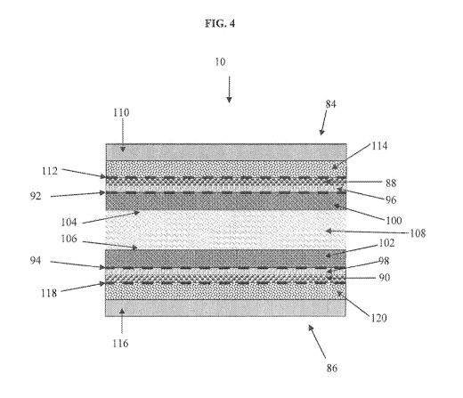
[0034] FIG. 4 is a cross-section detail view of a coated surface according to
another
embodiment of the invention. As shown in FIG. 4 the orthopaedic implant 10
includes
elements 84 and 86 in close proximity. In this embodiment, a multiple layer
coating may
be generated in and/or on each articulating surface of the orthopaedic implant
10. This is
achieved by performing the IBED process to form a second (outer) coating layer
in and out
from the surface of the first (inner) layer. Referring to FIG 4, one or both
top surfaces of
the coating (88 and 90) previously formed on the articulating surfaces of the
orthopaedic
implant 10 are shown at 92 and 94. A second material is first alloyed into and
below the
original surfaces 92 and 94 of the coatings 88 and 90 on each opposed element
84 and 86.
Sub-surface alloyed case layers 96 and 98 also provide bonding zones from
which thicker
layers of the second material can be grown as coatings of finite thickness,
100 and 102.
Since the second layer coatings 100 and 102 are grown continuously from sub-
surface
alloyed case layers 96 and 98, there is no distinct interface between the
original surfaces 92
and 94 of the first coating (88 and 90) and the second coatings 100 and 102,
and thus the
second coatings are relatively less likely to delaminate from the first
coatings 88 and 90 as
13
SUBSTITUTE SHEET (RULE 26)
CA 02719872 2010-09-28
WO 2009/123884 PCT/US2009/038034
compared to conventional coating procedures. Furthermore, the IBED process
allows a
high degree of control over the mechanical and metallurgical properties of the
second
coatings 100 and 102. The metallurgical composition can be maintained highly
uniform
throughout the second (outer) coating, thus properties like hardness and wear-
resistance
can be optimized to reduce or eliminate wear debris generation from the
metallic surface or
first (inner) coating beneath the second (outer) coating. The metallurgical
composition can
also be tailored to provide biologically active sites on the external surfaces
(104 and 106)
of the ceramic coating that attract and hold natural lubricants (synovial or
other
extracellular fluids) present in the tissue around the articulating elements.
These fluid
retentive surfaces provide a continuously forming thin layer of lubrication
108 between the
treated articulating elements which eliminates physical contact between the
surfaces of the
elements thus eliminating the generation and release of wear debris, corrosion
products,
and metallic ions into the body.
[00351 FIG. 5 is a cross-section detail view of a coated surfaces according to
another embodiment of the invention. As shown in FIG. 5, the articulating
opposed
element is fabricated from a metallic material and the counter facing opposed
element is
fabricated from either a plastic or ceramic material, and the surface of only
one element is
treated to reduce wear, corrosion, ion leaching and also to be self-
lubricated.
[00361 As shown in FIG. 5, the articulating orthopaedic implant 10 includes
opposed elements 130 and 132. In a particular example, the articulating
element 130 is
fabricated from a bulk metal alloy such as Co-Cr-Mo or Ti-Al-V (134) that has
the bulk
hardness and fracture-toughness required for optimum performance and long
useful life.
The counter facing articulating element (132) is fabricated from a bulk
plastic or ceramic
material. The original surface of the metallic articulating element is shown
at 136. Using
an IBED process, a ceramic material is first alloyed into and below the
original surface 136
of element 130. The presence of ceramic material in the sub-surface alloyed
case layer 138
produces a high concentration of compressive forces in the surface which helps
convert
retained tensile stresses in the surface to compressive stresses with a
consequent increase in
14
SUBSTITUTE SHEET (RULE 26)
CA 02719872 2010-09-28
WO 2009/123884 PCT/US2009/038034
fracture toughness of layer 138. The sub-surface alloyed case layer 138 also
provides a
bonding zone from which a thicker layer of the ceramic material can be grown
as a ceramic
coating 140 of finite thickness. Since the ceramic coating 140 is grown
continuously from
sub-surface alloyed case layer 138, there is no distinct interface between the
original
surface 136 and the coating 140, and thus the ceramic coating is less likely
to delaminate
from the surface 136 as compared to conventional coating methods. Furthermore,
the
IBED process allows a high degree of control over the mechanical and
metallurgical
properties of the ceramic coating 140. The metallurgical composition can be
maintained
highly uniform throughout the ceramic coating, thus properties like hardness
and wear-
resistance can be optimized to eliminate wear debris generation from the
metallic surface
beneath the ceramic coating. And coating grain sizes can be maintained in the
nanometer
(1X10⁻⁹ meter) range allowing the coating to grow void- and pinhole-free thus
eliminating
corrosion and ion leaching from the metallic surface beneath the ceramic
coating. The
metallurgical composition can also be tailored to provide biologically active
sites on the
external surface (142) of the ceramic coating that attract and hold natural
lubricants
(synovial or other extracellular fluids) present in the tissue around the
articulating
elements. These fluid retentive surfaces provide a continuously forming thin
layer of
lubrication 144 between the treated and untreated articulating elements that
eliminates
physical contact between the surfaces of the elements thus reducing or
eliminating the
generation and release of metallic and plastic or ceramic wear debris,
corrosion products,
and metallic ions into the body.
[00371 The IBED process used to form a ceramic coating in and on the surfaces
of
the metallic articulating elements proceeds as a continuous, uninterrupted,
two-step process
is outlined below in Table III:
Table III
Step 1 (Surface
Step 2 (Coating)
Texturing)
A B A B C D
SUBSTITUTE SHEET (RULE 26)
CA 02719872 2010-09-28
WO 2009/123884 PCT/US2009/038034
Initial case Thin
Coating Thicker
layer of conformal
Surface material coating grown
Article placed coating coating grown
textured by evolved and while
in vacuum ion beam material while
chamber deposited on alloyed into continuously continuously
sputtering surface of surface of augmented by augmented by
article article ion beam ion beam
[0038] FIG. 6 is a block diagram of a system for coating a surface according
to an
embodiment of the invention. As shown in FIG. 6, the treatment process may be
performed in a vacuum vessel 150. A high vacuum environment is preferably
maintained
in the vacuum vessel 150 in order to allow a high degree of control over the
quality of the
coating formed in and on the surface of the article. One or more articles 152
may be
affixed to a part platen 154. The part platen 154 is configured to provide
suitable control
of positioning of the articles during the separate cleaning and coating steps.
The part
platen 154 can rotate about its axis 156 and tilt about its center 158. The
tilt angles and
rotation rates are chosen such that the surfaces of the parts 152 to be
treated are cleaned at
the proper angle and the ceramic coating is applied at the proper angle and
with good
uniformity on the surfaces to be coated. A cleaning/augmenting ion beam source
160 is
located within the vacuum chamber and generates a broad beam of
cleaning/augmenting
ions 162. The broad beam of cleaning/augmenting ions 162 is configured to
perform initial
cleaning of the surface of the article by sputtering (first step). An electron
gun evaporator
164 is located within the vacuum vessel which produces evaporated coating
material 166.
The coating material 166 is sprayed onto the surface of the articles 152. The
electron gun
evaporator 164 is configured to contain multiple charges of coating material
if a multiple
layer coating is to be grown from the articulating surface of the implant. The
beam of
texturing/augmenting ions 162 is simultaneously applied to the surface of the
articles 152
and is used initially to mix the coating material into the surface of the
articles 152 forming
an alloyed case layer in the surface, and then used to control the composition
and crystal
structure of the coating as it is grown out from the alloyed case layer
(second step).
[0039] If multiple layers of coating material are to be applied, the beam of
texturing/augmenting 162 ions is simultaneously applied to the surface of the
first coating
16
SUBSTITUTE SHEET (RULE 26)
CA 02719872 2010-09-28
WO 2009/123884 PCT/US2009/038034
layer and is used initially to mix or ballistically embed the coating material
into the surface
of the first coating layer forming an alloyed case layer in the first coating
layer, and then
used to control the composition and crystal structure of the second coating
layer as it is
grown out from the first coating layer. During both the cleaning and
alloying/coating step,
the part platen 154 may be rotated about its axis 156 and oscillated about its
center 158 to
facilitate uniform coverage of the articles. A thickness measuring gauge 168
is positioned
near the part platen 154 in order to monitor the arrival of the evaporated
coating material
166 and control formation of the alloyed surface layer and then the thicker
coating grown
from the alloyed surface layer.
[0040] Preferably, the two-step treatment process is carried out sequentially
in the
same vacuum chamber without releasing the high vacuum to atmospheric pressure
between
steps. If this occurs a latent oxide layer will form on the cleaned surface
and will interfere
with the formation of the coating. It is also preferable to accurately control
the intensities
of the cleaning/augmenting ion beam and the angular position of the articles
to be treated
relative to this directional beam such that the surface alloyed layer and
coating are applied
uniformly to the surface to be treated.
[0041] Embodiments of the invention are further illustrated by the following
non-
limiting four Examples in which examples of particular coating parameter and
test data
associated with the coated items is presented.
[0042] Example 1:
[0043] Samples of Co-Cr-Mo materials used to manufacture the orthopaedic
implants 10 were prepared and coated with a ceramic coating as described
herein. The
samples were pins and disks utilized in the standard Pin-On-Disk wear test
procedure
(ASTM F732-00(2006) Standard Test Method for Wear Testing of Polymeric
Materials
Used in Total Joint Prostheses, American Society For Testing and Materials).
The wear of
the coated pin and disks was measured and compared to the wear found with
uncoated pins
and disks manufactured from the same Co-Cr-Mo material.
17
SUBSTITUTE SHEET (RULE 26)
CA 02719872 2010-09-28
WO 2009/123884 PCT/US2009/038034
[00441 In this case a two-layer coating was deposited on the pins and disks
using
the inventive IBED process. The first (inner) layer was titanium nitride (TiN)
and the
second (outer) layer was aluminum oxide (A1203). The procedures and processing
parameters utilized to deposit the two-layer coating on the pin and disk
sample materials
are as follows:
Table IV
Step 1: Surface Texturing
Description Process Parameters
Pin & Disk materials placed in vacuum
chamber on a rotatable articulated fixture
~' which allows programmed orientation of Vacuum: 1.OE(-07) Torr
the device during the process.
Surface of the Pin & Disk materials Ion Species: N
textured by ion beam sputtering with the ion Beam Energy: 1000 eV 2
B beam from the augmenting ion source and Beam Current: 4.4 mA/cm
manipulating the materials such that the Angle of incidence between 45-75
sputtering angle of incidence is maintained degrees
on the surfaces to be textured Part Platen Rotation: 30 RPM
Time: 10 minutes
Step 2: Coating by Vacuum Evaporation, TiN first (inner) layer, A1203 second
Description Process Parameters (TiN) Process Parameters (A1203)
Material: Ti Material: A1203
Part platen held at angle Part platen held at angle
E-gun evaporator used between 25 and 75 between 25 and 75 degrees to
to melt and evaporate degrees to evaporator flux evaporator flux
A coating material Evolution Rate: 14.5
continuously onto A/sec Evolution Rate: 10 A/sec
surface of Pin & Disk. Part Platen Rotation: 30 Part Platen Rotation: 30
RPM RPM
Temperature: < 200 F Temperature: 750 F
Ion species: N
Beam Energy: 1000 eV Ion species: Ar
Beam Energy: 1000 eV
Augmenting ion beam Beam Current: 4.4 2
used to alloy the first mA/cm2 Beam Current: 2.7 mA/cm
Material: A1203
few layers of the Material: Ti Part platen held at angle
B evaporated coating Part platen held at angle between 25 and 75 degrees to
material into device between 25 and 75
surface of the Pin & degrees to evaporator flux evaporator flux
Disk thus forming a Time: 40 seconds Time: 30 seconds
case layer. Part platen Rotation: 30 Part platen Rotation: 30
RPM
RPM
Tem erature: < 200 F Temperature: 750 F
18
SUBSTITUTE SHEET (RULE 26)
CA 02719872 2010-09-28
WO 2009/123884 PCT/US2009/038034
Thin conformal coatin Ion species: N
g Beam Energy: 800 eV Ion species: Ar
is grown out from the Beam Energy: 800 eV
alloyed case layer as Beam Current: 4.4 Beam Current: 2.7 mA/cm2
evaporation of the mA/cM2
Material: A1203
coating material Material: Ti Part platen held at angle
C continues. Part platen held at angle between 25 and 75 degrees to
between 25 and 75
Augmenting ion beam degrees to evaporator flux evaporator flux
used to control the Thickness: 50 A Thickness: 50 A
composition and Part Platen Rotation: 30
Part Platen Rotation: 30
crystal structure of the RPM RPM
coating as it is grown. Temperature: < 200 F Temperature: 750 F
Ion species: N Ion species: Ar
Coating is grown out Beam Energy: 800eV Beam Energy: 800eV
from the conformal Beam Current: 4.4 Beam Current: 2.7 mA/cm2
coating as evaporation mA/cm2 Material: A1203
of the coated material Material: Ti Part platen held at angle
D continues. Part platen held at angle between 25 and 75 degrees to
Augmenting ion beam between 25 and 75 evaporator flux
used to control the degrees to evaporator flux Thickness: 50,000 A
composition and Thickness: 10,000 A Part Platen Rotation: 30
crystal structure of the Part Platen Rotation: 30 RPM
coating as it is grown. RPM Temperature: 750 F
Temperature: < 200 F
[0045] The test conditions and results of the Pin-On-Disk testing are seen in
Table
V. In this test, the pin and disk sample materials coated with a two layer
TiN/A1203
coating. As a result of a run for 2,000,000 inches of wear travel in the Pin-
On-Disk tester a
volumetric loss of 0.25 mm3 is shown. This compares to a volumetric loss of
2.1 mm3
measured for 2,000,000 inches of wear travel for uncoated Co-Cr-Mo material.
TABLE V:
Comparison of Volumetric Wear Loss (ASTM, F732
Sample Material Load lbs/in2 # of Inches Loss mm3
IBED Coated Co-Cr-Mo 11,700 2,000,000 0.25
Co-Cr-Mol 11,700 2,000,000 2.1
[0046] Example 2:
1 (R.A. Poggie, "A Review Of The Effects Of Design, Contact Stress, And
Materials On The Wear Of
Metal-On-Metal Hip Prostheses," from Alternate Bearing Surfaces In Total Joint
Replacement,
American Society for Testing and Materials, Special Technical Publication STP
1346, 1998)
19
SUBSTITUTE SHEET (RULE 26)
CA 02719872 2010-09-28
WO 2009/123884 PCT/US2009/038034
[0047] A 5 micron thick single layer coating of chromium nitride (Cr2N) was
deposited on a 304 stainless steel panel using the inventive process described
in U.S. No.
11/042,150 and then tested for resistance to abrasive wear using a standard
Taber Abraser
Test. The test was applied using the procedure defined by Military Test
Specification
(MIL-A-8625F) in which an abrasive wheel (Taber, CS-10), impregnated with 50
micron
diameter corundum grits, is rubbed against the coating surface with a loading
of 2.2 pounds
of force, and run for 10,000 abrasion cycles. The wear loss is measured and
presented as
the number of microns of coating lost per 10,000 wear cycles.
[0048] The procedures and processing parameters utilized to deposit the single
layer Cr2N coating on the 304 stainless steel panel are described in Table VI
as follows:
Table VI
Step 1: Surface Texturing
Description Process Parameters
Panel material placed in vacuum
chamber on a rotatable
A articulated fixture which allows Vacuum: 1.OE(-07) Torr
programmed orientation of the
device during the process.
Surface of the Panel material Ion Species: N
textured by ion beam sputtering Beam Energy: 1000 eV
Beam Current: 4.4
with the ion beam from the mA/cm2
augmenting ion source and
B manipulating the materials such Angle of incidence
that the sputtering angle of between 45-75 degrees
incidence is maintained on the Part Platen Rotation: 30
RPM
surfaces to be textured
Time: 10 minutes
Step 2: Coating by Vacuum Evaporation, Cr2N
Process Parameters
Description
(Cr2N)
SUBSTITUTE SHEET (RULE 26)
CA 02719872 2010-09-28
WO 2009/123884 PCT/US2009/038034
Material: Cr
Part platen held at angle
E-gun evaporator used to melt between 25 and 75
A and evaporate coating material degrees to evaporator flux
continuously onto surface of the Evolution Rate: 12 A/sec
Panel. Part Platen Rotation: 30
RPM
Temperature: < 200 'F
Ion species: N
Beam Energy: 1000 eV
Beam Current: 3.4
Augmenting ion beam used to mA/cm2
alloy the first few layers of the Material: Cr
B evaporated coating material into Part platen held at angle
device surface of the Panel thus between 25 and 75
forming a case layer. degrees to evaporator flux
Time: 40 seconds
Part platen Rotation: 30
RPM
Temperature: < 200 'F
Ion species: N
Beam Energy: 800 eV
Thin conformal coating is grown Beam Current: 3.4
out from the alloyed case layer mA/cm2
as evaporation of the coating Material: Cr
C material continues. Augmenting Part platen held at angle
ion beam used to control the between 25 and 75
composition and crystal degrees to evaporator flux
structure of the coating as it is Thickness: 50 A
grown. Part Platen Rotation: 30
RPM
Temperature: < 200 OF
Ion species: N
Beam Energy: 800eV
Coating is grown out from the Beam Current: 3.4
conformal coating as mA/cm2
evaporation of the coated Material: Cr
D material continues. Augmenting Part platen held at angle
ion beam used to control the between 25 and 75
composition and crystal degrees to evaporator flux
structure of the coating as it is Thickness: 50,000 A
grown. Part Platen Rotation: 30
RPM
Temperature: < 200 'F
21
SUBSTITUTE SHEET (RULE 26)
CA 02719872 2010-09-28
WO 2009/123884 PCT/US2009/038034
[0049] The result of the Taber Abrasive Wear Testing is seen in Table VII. The
IBED Cr2N coating, showed a loss of 0.15 microns ( ) in thickness for the
10,000 cycles of
abrasive wear. This compares to a thickness loss of 2.82 microns measured for
10,000
cycles of abrasive wear on uncoated Co-Cr-Mo material with a Rockwell "C"
Scale
Hardness of 45, that typical of material used for orthopaedic hip and knee
implant
components.
TABLE VII: Taber Wear Measurement MIL-A-8625F
Material Abrasive # of Cycles Wear
IBED Cr2N Coating CS-10 10,000 0.15
Co-Cr-Mo (Rc 45) CS-10 10.000 2.82
[0050] Example 3:
[0051] A 5 micron thick single layer coating of aluminum oxide (A1203) was
deposited on a 304 stainless steel panel as described herein and then tested
for resistance to
abrasive wear using a standard Taber Abraser Test. The test was applied using
the
procedure defined by Military Test Specification (MIL-A-8625F) in which an
abrasive
wheel (Taber, CS-10), impregnated with 50 micron diameter corundum grits, is
rubbed
against the coating surface with a loading of 2.2 pounds of force, and run for
10,000
abrasion cycles. The wear loss is measured and presented as the number of
microns of
coating lost per 10,000 wear cycles.
[0052] The procedures and processing parameters utilized to deposit the single
layer A1203 coating on the 304 stainless steel panel are illustrated in Table
VIII as follows:
Table VIII
Step 1: Surface Texturing
Description Process Parameters
Panel material placed in vacuum
chamber on a rotatable
A articulated fixture which allows Vacuum: 1.OE(-07) Torr
programmed orientation of the
device during the process.
22
SUBSTITUTE SHEET (RULE 26)
CA 02719872 2010-09-28
WO 2009/123884 PCT/US2009/038034
Surface of the Panel material Ion Species: Ar
1000 eV
textured by ion beam sputtering Beam Beam Energy: Current: 4.4
with the ion beam from the mA/cm2
augmenting ion source and
B manipulating the materials such Angle of incidence
that the sputtering angle of between 45-75 degrees
incidence is maintained on the Part Platen Rotation: 30
surfaces to be textured RPM
Time: 10 minutes
Step 2: Coating by Vacuum Evaporation, A1203
Process Parameters
Description
(A1203)
Material: A1203
Part platen held at angle
E-gun evaporator used to melt between 25 and 75
A and evaporate coating material degrees to evaporator flux
continuously onto surface of the Evolution Rate: 12 A/sec
Panel. Part Platen Rotation: 30
RPM
Temperature: < 200 F
Ion species: Ar
Beam Energy: 1000 eV
Beam Current: 2.7
mA/cm2
Augmenting ion beam used to Material: A1203
alloy the first few layers of the part platen held at angle
B evaporated coating material into
device surface of the Panel thus between 25 and 75
forming a case layer. degrees to evaporator flux
Time: 40 seconds
Part platen Rotation: 30
RPM
Temperature: < 200 OF
Ion species: Ar
Beam Energy: 800 eV
Thin conformal coating is grown Beam Current: 2.7
out from the alloyed case layer mA/cm2
as evaporation of the coating Material: A1203
C material continues. Augmenting Part platen held at angle
ion beam used to control the between 25 and 75
composition and crystal degrees to evaporator flux
structure of the coating as it is Thickness: 50 A
grown. Part Platen Rotation: 30
RPM
Temperature: < 200 -F
23
SUBSTITUTE SHEET (RULE 26)
CA 02719872 2010-09-28
WO 2009/123884 PCT/US2009/038034
Ion species: Ar
Beam Energy: 800eV
Coating is grown out from the Beam Current: 2.7
conformal coating as mA/cm2
evaporation of the coated Material: A1203
D material continues. Augmenting Part platen held at angle
ion beam used to control the between 25 and 75
composition and crystal degrees to evaporator flux
structure of the coating as it is Thickness: 50,000 A
grown. Part Platen Rotation: 30
RPM
Temperature: < 200 'F
[0053] The result of the Taber Abrasive Wear Testing is seen in Table IX. The
IBED A1203 coating, showed a loss of 0.07 microns ( ) in thickness for the
10,000 cycles
of abrasive wear. This compares to a thickness loss of 2.82 microns measured
for 10,000
cycles of abrasive wear on uncoated Co-Cr-Mo material with a Rockwell "C"
Scale
Hardness of 45, that typical of material used for orthopaedic hip and knee
implant
components.
TABLE IX: Taber Wear Measurement (lVHL-A-8625F)
Material Abrasive # of Cycles Wear
113ED A1203 Coating CS-10 10,000 0.07
Co-Cr-Mo Rc 45 CS-10 10.000 2.82
[0054] Example 4:
[0055] Pin and disk samples were prepared from Co-Cr-Mo material used to
manufacture orthopaedic implants, and then coated with a ceramic coating as
described
herein in order to test the fluid retentive properties of the deposited
ceramic. In this case a
two-layer coating was deposited on the Co-Cr-Mo pin and disk using the
inventive IBED
process. The first (inner) layer was titanium nitride (TiN) and the second
(outer) layer was
aluminum oxide (A1203). The procedures and processing parameters utilized to
deposit the
two-layer coating on the Co-Cr-Mo pin and disk samples are illustrated in
Table X as
follows:
24
SUBSTITUTE SHEET (RULE 26)
CA 02719872 2010-09-28
WO 2009/123884 PCT/US2009/038034
Table X: Step 1: Surface Texturing
Description Process Parameters
Pin & Disk materials placed in vacuum
chamber on a rotatable articulated
A fixture which allows programmed Vacuum: 1.OE(-07) Torr
orientation of the device during the
process.
Surface of the Pin & Disk materials Ion Species: N
textured by ion beam sputtering with the Beam Energy: 1000 eV
ion beam from the augmenting ion Beam Current: 4.4 mA/cm2
B source and manipulating the materials Angle of incidence between 45-75
such that the sputtering angle of degrees
incidence is maintained on the surfaces Part Platen Rotation: 30 RPM
to be textured Time: 10 minutes
Step 2: Coating by Vacuum Evaporation, TiN first (inner) layer, A1203 second
Description Process Parameters (TiN) Process Parameters (A1203)
Material: Ti Material: A1203
E-gun evaporator Part platen held at angle Part platen held at angle
used to melt and between 25 and 75 between 25 and 75 degrees to
evaporate coating degrees to evaporator flux evaporator flux
A material Evolution Rate: 14.5
continuously onto A/sec Evolution Rate: 10 A/sec
surface of Pin & Part Platen Rotation: 30 Part Platen Rotation: 30
RPM
Disk. RPM
Temperature: < 200 F Temperature: 750 F
Ion species: N Ion species: Ar
Augmenting ion Beam Energy: 1000 eV Beam Energy: 1000 eV
beam used to alloy Beam Current: 4.4 Beam Current: 2.7 mA/cm2
the first few layers mA/cM2
Material: A1203
of the evaporated Material: Ti Part platen held at angle
B coating material Part platen held at angle between 25 and 75 degrees to
into device surface between 25 and 75 evaporator flux
of the Pin & Disk degrees to evaporator flux Time: 30 seconds
thus forming a Time: 40 seconds Part platen Rotation: 30
case layer. Part platen Rotation: 30 RPM
RPM
Temperature: < 200 F Temperature: 750 F
SUBSTITUTE SHEET (RULE 26)
CA 02719872 2010-09-28
WO 2009/123884 PCT/US2009/038034
Thin conformal
coating is grown Ion species: N
out from the Beam Energy: 800 eV Ion species: Ar
Beam Energy: 800 eV
alloyed case layer Beam Current: 4.4 2
Beam Current: 2.7 mA/cm
as evaporation of mA/cm2 Material: A1203
the coating Material: Ti Part platen held at angle
C material continues. Part platen held at angle between 25 and 75 degrees to
Augmenting ion between 25 and 75
beam used to degrees to evaporator flux evaporator flux
control the Thickness: 50 A Thickness: 50 A
composition and Part Platen Rotation: 30 Part Platen Rotation: 30
RPM
crystal structure of RPM
the coating as it is Temperature: < 200 F Temperature: 750 F
grown.
Coating is grown Ion species: N
out from the Beam Energy: 800eV Ion species: Ar
conformal coating Beam Energy: 800eV
as evaporation of Beam Current: 4.4 Beam Current: 2.7 mA/cm2
the coated material mA/cm Material: Ti Material: A12O3
continues. Part platen held at angle Part platen held at angle
D
Augmenting ion between 25 and 75 between 25 and 75 degrees to
beam used to degrees to evaporator flux evaporator flux
control the Thickness: 50,000 A
composition and Thickness: 10,000 A Part Platen Rotation: 30
crystal structure of Part Rotation: 30 RPM
the coating as it is Temperature: < 200 F Temperature: 750 F
grown.
[0056] An additional set of pin-on-disk samples was prepared from solid,
single
crystal, alpha phase A1203. The counter facing surfaces of this pin-on-disk
set would not
have the same surface nanostructure, and thus fluid-retentive properties, as
would the
A1203 coating deposited on the Co-Cr-Mo samples using the inventive process.
[0057] Both sample pin and disk sets were tested according to the standard pin-
on-
disk wear test procedure (ASTM F732-00(2006) "Standard Test Method for Wear
Testing
of Polymeric Materials Used in Total Joint Prostheses, American Society for
Testing and
Materials"). The samples were immersed in defined bovine calf serum as a
lubricant
(Hyclone Labs: Cat. No. SH30073.04) during the entirety of the test. After
completion of
2,000,000 cycles in the pin-on-disk test, both sample sets were carefully
dried and the
26
SUBSTITUTE SHEET (RULE 26)
CA 02719872 2010-09-28
WO 2009/123884 PCT/US2009/038034
surface the pins imaged using scanning electron microscopy (SEM), and the
surface
composition analyzed with energy dispersive X-ray analysis (EDAX).
[0058] No residue was detected by either SEM imaging or EDAX analysis on the
surface of the single crystal, alpha phase, pin indicating that the surface of
the solid A1203
pin did not have the properties of a fluid-retentive surface. The IBED-coated
Co-Cr-Mo
pin surface did however show remnants of a film that had been retained on the
surface of
the A1203 coating. FIG. 7, is a scanning electron micrograph image of the pin
surface
showing remnants of the lubricating film still adhered to the surface of the
A1203 coating.
FIG. 8 is an energy dispersive X-ray analysis showing the presence of both Ca
and P
cations which are inorganic elements present in the defined bovine calf serum
proteins.
Thus it is confirmed that the structure and surface activity of A1203 coatings
as deposited
by the inventive IBED process acts as a fluid retentive surface which
maintains the self-
lubricating performance of orthopaedic implants so-treated.
[0059] Conclusions:
[0060] The orthopaedic implants 10 with surface treatments provided by this
invention will generate less debris in the form of wear products, corrosion
products, and
metallic ion leaching which are liberated and transported to bone, blood, the
lymphatic
system, and other internal organs. This will result in less inflammation,
toxicity, and
immune response resulting in increased longevity of the orthopaedic implant 10
and less
adverse effects on the patient. The surface treatments can be applied to a
variety of the
materials used to fabricate the articulating elements of the modular
orthopaedic implants
10, and are useful for a variety of combinations of metal, ceramic, and
polyethylene
articulating elements.
[0061] The many features and advantages of the invention are apparent from the
detailed specification, and thus, it is intended by the appended claims to
cover all such
features and advantages of the invention which fall within the true spirit and
scope of the
invention. Further, since numerous modifications and variations will readily
occur to those
skilled in the art, it is not desired to limit the invention to the exact
construction and
27
SUBSTITUTE SHEET (RULE 26)
CA 02719872 2010-09-28
WO 2009/123884 PCT/US2009/038034
operation illustrated and described, and accordingly, all suitable
modifications and
equivalents may be resorted to, falling within the scope of the invention.
28
SUBSTITUTE SHEET (RULE 26)