Language selection

Search

Patent 2794486 Summary

Third-party information liability

Some of the information on this Web page has been provided by external sources. The Government of Canada is not responsible for the accuracy, reliability or currency of the information supplied by external sources. Users wishing to rely upon this information should consult directly with the source of the information. Content provided by external sources is not subject to official languages, privacy and accessibility requirements.

Claims and Abstract availability

Any discrepancies in the text and image of the Claims and Abstract are due to differing posting times. Text of the Claims and Abstract are posted:

  • At the time the application is open to public inspection;
  • At the time of issue of the patent (grant).
(12) Patent Application: (11) CA 2794486
(54) English Title: ZEBRITA MAGNETIC DRIVEN SPHERE WHEELS
(54) French Title: ROUES SPHERIQUES A ENTRAINEMENT MAGNETIQUE ZEBRITA
Status: Dead
Bibliographic Data
(51) International Patent Classification (IPC):
  • B60B 19/14 (2006.01)
  • B60L 13/04 (2006.01)
  • F16H 49/00 (2006.01)
  • H02K 1/06 (2006.01)
(72) Inventors :
  • MASON, COLIN (Canada)
(73) Owners :
  • MASON, COLIN (Canada)
(71) Applicants :
  • MASON, COLIN (Canada)
(74) Agent: NA
(74) Associate agent: NA
(45) Issued:
(22) Filed Date: 2012-11-02
(41) Open to Public Inspection: 2014-05-02
Availability of licence: N/A
(25) Language of filing: English

Patent Cooperation Treaty (PCT): No

(30) Application Priority Data: None

Abstracts

English Abstract


My invention called "Zebrita Magnetic Driven Sphere Wheels", uses a specified
pattern enclosure
with magnetic force to lift and circumshpereilate; with natural and electric
sequenced magnets
attached inside a sphere wheel with normal rubber round the tire in a sphere
for proper rotation
and gear power clutch switching.

Claims

Note: Claims are shown in the official language in which they were submitted.
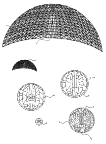

Zebrita Driven Magnetic Sphere Wheels
Claims:
The embodiments of the invention in which and exclusive property or privilege
is claimed are
defined as follows:
A In the case of an apparatus-
A driven sphere wheel that uses magnetic force from a battery and computer
sequenced
electricity for motion with gear switching compromising a stationary round
wheeled vehicle.
1 A tool defined in claim I, where a sphere wheel has natural magnets in
specified areas.
2 A tool defined in claim I, in which there is a sphere gear switch.
3 A tool defined in claim 1, in which there is a center sphere core.
4 A tool defined in claim 1, in which there is an outside sphere wheel.
B In the case of the process-
1 A process defined in claim 2, in which the sphere shell transfers a
sequenced pattern electricity
to the inside gear switching wheel.
2 A process defined in claim 4, in which the sphere gear switch can rotate
freely and lock with
sequenced magnetic electricity.
4 A process defined in claim 1, in which the natural magnet placements are
sequenced for gear
switching.
A process defined in claim 2, where it locks to claim 4.

Description

Note: Descriptions are shown in the official language in which they were submitted.


CA 02794486 2012-11-02
Zebrita Magnetic Driven Sphere Wheels
Specification:
Back in early 2000 I had thought of a better way to travel on a mechanical
driven system. It
consisted of tracks that are magnetic lifted with all about movement. I did
design some early
paper thinking prototype heavy machinery that could push the limits of hard
metal fatigue with
magnetic force. I now have completed mostly the inside mechanics and patterns
to correlate a
stuck, lifted, and over drive with gear switching sphere wheel.
The main purpose of this magnetic lifting sphere wheel system is for a
smoother ride and more
control over where you are on a road and safety. Some people may think that a
lifted mid air
wheel might depart or run away, but technically there would be a full stop run
out from a clutch
system like in a motorbike spin clutch mechanism. The stability would come
from a sequenced
magnetic force pattern in computer to wheel shell to inside the sphere gear
clutch to outside of the
sphere wheel, then control to the road from a user driving person.
The pattern I designed (8) gives to me the easiest ultimate class in all wheel
and all circumstances
of driving conditions. The patterns (8 ) of placed natural monitored sensed
magnets and computer
sequenced along with battery will output patterned electricity to magnets and
will firstly push the
gear clutch (5) out onto the outside (4) (6). The gear clutch (4) serves as a
gear that can spin
freely inside the sphere wheel and pull lock according to the speed and torch
the driver needs.
The sphere wheel shell (3) is built into a vehicle and connected to a computer
and battery and has
the most repel force and retract force to spin the sphere wheel around (8).
The magnetic patterns
(2) I designed on the wheel shell will allow a full half sphere of control to
the sphere wheel.
These are the magnet segments (2) that will be sequenced to the sphere wheel
(6) depending on
what driving condition you are in.
Driving Straight 100 km/h and passing will be overdrive (7) and the inside
gear clutch will be
straight with the skinny magnets so that we have a speed gear. The rest of the
sphere wheel (8)
are for slow cautious, power and miniature movements. Now to control the
wheels from the
driver it could be from at least a steering wheel that corresponds turning
into four sphere wheels
turning properly like on a conventional right round of today's vehicles. The
other option would be
to either use a handheld controller for steering with a d-pad. Or just have a
d-pad on the steering
wheel to definitely control the vehicle like in strafe and more rounded
precision on the spot
decisions from the driver.

CA 02794486 2012-11-02
Zebrita Driven Magnetic Sphere Wheels
The core of the sphere wheel (9) will be made of lead or substituted for
another heavy metal to
keep the sphere wheel heavy on the ground and to help keep the frame ect.. on
movement. The
lead metal core will also be inside to stop the computers battery pattern
sequenced heavy
magnetic force onto the sphere wheel overcome and regenerate to extreme
levels.
I have yet to determine the magnetic force in electricity and natural magnetic
force but mainly the
natural magnets will be mostly used for the lifting force to about 30
centimetres for suspension
and each specified weight of load will be determined by weight censors and
inside vehicle camera
scanning.

Representative Drawing
A single figure which represents the drawing illustrating the invention.
Administrative Status

For a clearer understanding of the status of the application/patent presented on this page, the site Disclaimer , as well as the definitions for Patent , Administrative Status , Maintenance Fee  and Payment History  should be consulted.

Administrative Status

Title Date
Forecasted Issue Date Unavailable
(22) Filed 2012-11-02
(41) Open to Public Inspection 2014-05-02
Dead Application 2015-11-03

Abandonment History

Abandonment Date Reason Reinstatement Date
2014-11-03 FAILURE TO PAY APPLICATION MAINTENANCE FEE

Payment History

Fee Type Anniversary Year Due Date Amount Paid Paid Date
Application Fee $200.00 2012-11-02
Owners on Record

Note: Records showing the ownership history in alphabetical order.

Current Owners on Record
MASON, COLIN
Past Owners on Record
None
Past Owners that do not appear in the "Owners on Record" listing will appear in other documentation within the application.
Documents

To view selected files, please enter reCAPTCHA code :


To view images, click a link in the Document Description column. To download the documents, select one or more checkboxes in the first column and then click the "Download Selected in PDF format (Zip Archive)" or the "Download Selected as Single PDF" button.

List of published and non-published patent-specific documents on the CPD .

If you have any difficulty accessing content, you can call the Client Service Centre at 1-866-997-1936 or send them an e-mail at CIPO Client Service Centre.


Document
Description 
Date
(yyyy-mm-dd) 
Number of pages   Size of Image (KB) 
Abstract 2012-11-02 1 10
Description 2012-11-02 2 76
Claims 2012-11-02 1 25
Drawings 2012-11-02 2 85
Representative Drawing 2014-04-07 1 21
Cover Page 2014-05-12 1 47
Correspondence 2012-11-19 1 18
Assignment 2012-11-02 4 105
Correspondence 2012-12-18 1 17