Note: Descriptions are shown in the official language in which they were submitted.
WO 2012/021971 CA 02808323 2013-02-14PCT/CA2011/000928
FLUID FILTER DEVICE
CROSS-REFERENCE TO RELATED APPLICATION
[0001] The present application claims the benefit under 35 U.S.C. 119(e) of
provisional patent
application S.N. 61/375,448, filed August 20, 2010, the contents of which are
hereby
incorporated by reference.
BACKGROUND OF THE INVENTION
FIELD OF THE INVENTION
[0002] In one of its aspects, the present invention relates to a fluid filter
device. In another of its
aspects, the present invention relates to a fluid isolation device.
DESCRIPTION OF THE PRIOR ART
[0003] Fluid treatment systems are generally known in the art. More
particularly, ultraviolet
(UV) radiation fluid treatment systems are generally known in the art. Early
treatment systems
comprised a fully enclosed chamber design containing one or more radiation
(preferably UV)
lamps. Certain problems existed with these earlier designs. These problems
were manifested
particularly when applied to large open flow treatment systems which are
typical of larger scale
municipal waste water or potable water treatment plants. Thus, these types of
reactors had
associated with them the following problems:
= relatively high capital cost of reactor;
= difficult accessibility to submerged reactor and/or wetted equipment
(lamps, sleeve cleaners, etc);
= difficulties associated with removal of fouling materials from fluid
treatment equipment;
= relatively low fluid disinfection efficiency, and/or
SUBSTITUTE SHEET (RULE 26)
WO 2012/021971 CA 02808323 2013-02-14PCT/CA2011/000928
= full redundancy of equipment was required for maintenance of wetted
components (sleeves, lamps and the like).
[0004] The shortcomings in conventional closed reactors led to the development
of the so-called
"open channel" reactors.
[0005] For example, United States patents 4,482,809, 4,872,980 and 5,006,244
(all in the name
of Maarschalkerweerd and all assigned to the assignee of the present invention
and hereinafter
referred to as the Maarschalkerweerd #1 Patents) all describe gravity fed
fluid treatment systems
which employ ultraviolet (UV) radiation.
[0006] Such systems include an array of UV lamp modules (e.g., frames) which
include several
UV lamps each of which are mounted within sleeves which extend between and are
supported by
a pair of legs which are attached to a cross-piece. The so-supported sleeves
(containing the UV
lamps) are immersed into a fluid to be treated which is then irradiated as
required. The amount
of radiation to which the fluid is exposed is determined by the proximity of
the fluid to the
lamps, the output wattage of the lamps and the flow rate of the fluid past the
lamps. Typically,
one or more UV sensors may be employed to monitor the UV output of the lamps
and the fluid
level is typically controlled, to some extent, downstream of the treatment
device by means of
level gates or the like.
[0007] The Maarschalkerweerd #1 Patents teach fluid treatment systems which
were
characterized by improved ability to extract the equipment from a wetted or
submerged state
without the need for full equipment redundancy. These designs
compartmentalized the lamp
arrays into rows and/or columns and were characterized by having the top of
the reactor open to
provide free-surface flow of fluid in a "top open" channel.
[0008] The fluid treatment system taught in the Maarschalkerweerd #1 Patents
is characterized
by having a free-surface flow of fluid (typically the top fluid surface was
not purposely
controlled or constrained). Thus, the systems would typically follow the
behaviour of open
channel hydraulics. Since the design of the system inherently comprised a free-
surface flow of
fluid, there were constraints on the maximum flow each lamp or lamp array
could handle before
2
SUBSTITUTE SHEET (RULE 26)
WO 2012/021971 CA 02808323 2013-02-14 PCT/CA2011/000928
either one or other hydraulically adjoined arrays would be adversely affected
by changes in water
elevation. At higher flows or significant changes in the flow, the
unrestrained or free-surface
flow of fluid would be allowed to change the treatment volume and cross-
sectional shape of the
fluid flow, thereby rendering the reactor relatively ineffective. Provided
that the power to each
lamp in the array was relatively low, the subsequent fluid flow per lamp would
be relatively low.
The concept of a fully open channel fluid treatment system would suffice in
these lower lamp
power and subsequently lower hydraulically loaded treatment systems. The
problem here was
that, with less powerful lamps, a relatively large number of lamps was
required to treat the same
volume of fluid flow. Thus, the inherent cost of the system would be unduly
large and/or not
competitive with the additional features of automatic lamp sleeve cleaning and
large fluid
volume treatment systems.
[0009] This led to the so-called "semi-enclosed" fluid treatment systems.
[0010] United States patents 5,418,370, 5,539,210 and Re36,896 (all in the
name of
Maarschalkerweerd and all assigned to the assignee of the present invention
and hereinafter
referred to as the Maarschalkerweerd #2 Patents) all describe an improved
radiation source
module for use in gravity fed fluid treatment systems which employ UV
radiation. Generally,
the improved radiation source module comprises a radiation source assembly
(typically
comprising a radiation source and a protective (e.g., quartz) sleeve)
sealingly cantilevered from a
support member. The support member may further comprise appropriate means to
secure the
radiation source module in the gravity fed fluid treatment system.
[0011] The Maarschalkerweerd #2 Patents are characterized by having a closed
surface
confining the fluid being treated in the treatment area of the reactor. This
closed treatment
system had open ends which, in effect, were disposed in an open channel. The
submerged or
wetted equipment (UV lamps, cleaners and the like) could be extracted using
pivoted hinges,
sliders and various other devices allowing removal of equipment from the semi-
enclosed reactor
to the free surfaces.
[0012] The fluid treatment system described in the Maarschalkerweerd #2
Patents was typically
characterized by relatively short length lamps which were cantilevered to a
substantially vertical
3
SUBSTITUTE SHEET (RULE 26)
WO 2012/021971 CA 02808323 2013-02-14 PCT/CA2011/000928
support arm (i.e., the lamps were supported at one end only). This allowed for
pivoting or other
extraction of the lamp from the semi-enclosed reactor. These significantly
shorter and more
powerful lamps inherently are characterized by being less efficient in
converting electrical
energy to UV energy. The cost associated with the equipment necessary to
physically access and
support these lamps was significant.
100131 Historically, the fluid treatment modules and systems described in the
Maarschalkerweerd #1 and #2 Patents have found widespread application in the
field of
municipal waste water treatment (i.e., treatment of water that is discharged
to a river, pond, lake
or other such receiving stream).
100141 In the field of municipal drinking water, it is known to utilize so-
called "closed" fluid
treatment systems or "pressurized" fluid treatment systems.
100151 Closed fluid treatment devices are known ¨ see, for example, United
States patent
5,504,335 (Maarschalkerweerd #3). Maarschalkerweerd #3 teaches a closed fluid
treatment
device comprising a housing for receiving a flow of fluid. The housing
comprises a fluid inlet, a
fluid outlet, a fluid treatment zone disposed between the fluid inlet and the
fluid outlet, and at
least one radiation source module disposed in the fluid treatment zone. The
fluid inlet, the fluid
outlet and the fluid treatment zone are in a collinear relationship with
respect to one another. The
at least one radiation source module comprises a radiation source sealably
connected to a leg
which is sealably mounted to the housing. The radiation source is disposed
substantially parallel
to the flow of fluid.
[0016] United States patent 6,500,346 [Taghipour et al. (Taghipour)] also
teaches a closed fluid
treatment device, particularly useful for ultraviolet radiation treatment of
fluids such as water.
The device comprises a housing for receiving a flow of fluid. The housing has
a fluid inlet, a
fluid outlet, a fluid treatment zone disposed between the fluid inlet and the
fluid outlet and at
least one radiation source having a longitudinal axis disposed in the fluid
treatment zone
substantially transverse to a direction of the flow of fluid through the
housing. The fluid inlet, the
fluid outlet and the fluid treatment zone are arranged substantially
collinearly with respect to one
another. The fluid inlet has a first opening having: (i) a cross-sectional
area less than a cross-
4
SUBSTITUTE SHEET (RULE 26)
WO 2012/021971 CA 02808323 2013-02-14 PCT/CA2011/000928
sectional area of the fluid treatment zone, and (ii) a largest diameter
substantially parallel to the
longitudinal axis of the at least one radiation source assembly.
[0017] The various embodiments described in the the Maarshalkerweerd #1
Patents, the
Maarschalkerweerd #2 Patents, the Maarschalkerweerd #3 Patents and Taghipour
relate to land-
based fluid radiation treatment systems. Typically, the fluid radiation
treatment systems are used
in conjunction with other treatment systems in the municipal wastewater
treatment plant or the
municipal drinking water treatment plant, as the case may be. In such
installations, various
conduit systems and the like are used to interconnect the fluid radiation
treatment system to the
other fluid treatment systems in the installation.
[0018] It is conventional in such installations to compartmentalize each
treatment system in the
installation such that each treatment system is configured to create its own
optimized flow fluid.
This approach has been satisfactory for land-based fluid treatment systems.
[0019] A problem arises in applications of fluid treatment systems where a
very small footprint
is available for overall fluid treatment. This problem arises particularly
when it is desired to treat
ballast water in shipping vessels.
[0020] The continuous introduction and spread of aquatic non-indigenous
species is a serious
threat to the marine environment. Unlike other forms of pollution, once a non-
indigenous
species establishes itself', it will remain in its new location. While
calculating the potential side
effects on human food supply, economy, health and overall biodiversity is
difficult, there is
widespread acceptance that the cost could be staggering.
[0021] One primary culprit for introduction and spread of aquatic non-
indigenous species is due
to unabated transferance of ballast water from shipping vessels. Ballast water
taken on in one
body of water or ecological zone and released into another body of water or
ecological zone can
introduce so-called Aquatic Invasive Species (AIS) that has the potential to
cause detrimental
impact on one or more of the biodiversity, economy and human health of the
receiving
community.
5
SUBSTITUTE SHEET (RULE 26)
WO 2012/021971 CA 02808323 2013-02-14PCT/CA2011/000928
[0022] Typically, a shipping vessel will take on ballast water (fresh water
and/or salt water) and
at a source point and hold this in onboard ballast tanks and/or cargo holds to
increase stability
and maneuverability during transit. Once the shipping vessel arrives at its
destination point, the
ballast water is typically discharged from the onboard ballast tanks and/or
cargo holds. Also, it
is common for ballast water to be taken on and/or discharged during transit
between the source
point and the destination point. It has been estimated that 3-5 billon tonnes
of ballast water is
transferred in this manner on an annual basis.
[0023] Co-pending United States patent application S.N. 12/777,691 [Fraser]
teaches a fluid
treatment system particularly well suited for treatment of ballest water on a
shipping vessel.
More particularly, the fluid treatment system comprises: (i) a fluid inlet;
(ii) a fluid outlet; and
(iii) a fluid treatment zone in fluid communication with the fluid inlet and
the fluid outlet. The
fluid treatment zone comprises a housing within which is disposed a fluid
separation section (the
separation section may include a single separation device or a combination of
two or more
similar or disimilar separation devices) and a fluid radiation section in
fluid communication with
one another. The fluid separation section removes solids in the fluid and the
fluid radiation
section irradiates the fluid to deactive microorganisms in the fluid. The
fluid separation section
and the fluid radiation section are configured to have a substantially common
fluid flow path
which significantly reduces the space or footprint requirement of and/or
significantly reduces
hydraulic head loss (pressure drops) in the overall fluid treatment system
while allowing the two
sections to perform their respective functions.
[0024] While the fluid treatment system taught by Fraser is an advance in the
art, there is room
for improvement.
[0025] Specifically, while the fluid treatment system taught by Fraser
describes a so-called fluid
separation section for removal of solids in the fluid, there are areas of
potential improvement.
For example, it is known ballast water can contain bacteria, zooplankton,
phytoplankton and the
like. As is known, ultraviolet radiation can be used to treat bacteria,
filtration can be used to
treat (remove) zooplankton and either ultraviolet radiation or filtration can
be used to treat
phytoplankton.
6
SUBSTITUTE SHEET (RULE 26)
WO 2012/021971 CA 02808323 2013-02-14PCT/CA2011/000928
[0026] When the fluid treatment system taught by Fraser is installed in a
shipping vessel, it is
important to optimize ship resources such as pump head, available space and
electrical power.
On the one hand, if the fluid separation section utilizes a filter that is too
coarse, too much
particular material will be passed through the filter thereby necessitating
the use higher amounts
of ultraviolet radiation ¨ i.e., this causes an increase in the amount of
electrical power necessary
to treat the ballast water. On the other hand if the fluid separation section
utilizes a filter that is
too fine, valuable pump head is lost during ballast water treatment and/or
exchange.
100271 Accordingly, there is a need for a filter device that can be
implemented in the fluid
treatment system taught by Fraser which achieves an acceptable balance between
treatment of
microorganisms by the fluid radiation section and reducing the amount of power
consumption
required to operate the fluid radiation section.
SUMMARY OF THE INVENTION
100281 It is an object of the present invention to obviate or mitigate at
least one of the above-
mentioned disadvantages of the prior art.
[0029] It is another object of the present invention to provide a fluid filter
device.
[0030] It is another object of the present invention to provide a fluid
isolation device.
[0031] Accordingly, in one of its aspects, the present invention provides a
fluid filter device
comprising:
a primary filter section having a first porous section; and
a secondary filter section having second porous section;
wherein: (i) the primary filter section and the secondary filter section are
in fluid
communication with one another, and (ii) the first porous section has a
greater porosity than the
second porous section.
100321 In another of its aspects, the present invention provides a fluid
isolation device for
isolation an exterior fluid from a surface of an enclosure containing interior
fluid, the device
comprising a sleeve element movable between: (i) a retracted portion in which
exterior fluid
7
SUBSTITUTE SHEET (RULE 26)
WO 2012/021971 CA 02808323 2013-02-14 PCT/CA2011/000928
contacts the surface of the enclosure, and (ii) an extended position in which
exterior fluid is
isolated from contacting the surface of the enclosure; a distal portion of the
sleeve element
configured to actuate a backwash element configured to backwash interior fluid
from the
enclosure when the sleeve element is in the extended position.
[0033] Thus, the present inventors have discovered a novel fluid filter device
which is
particularly well suited for use with the fluid treatment system described in
co-pending United
States patent application S.N. 12/777,691 [Fraser] described above. Of course,
the present fluid
filter device can be used in a number of other applications.
[0034] The following advantages accrue from the present fluid filter device:
= the advantages of a so-called fine filter while mitigating or obviating the
disadvantages of such a filter due to quick clogging that normally occurs ¨
this is achieved by separating a significant portion of coarser fouling
materials
from the flow stream via an upstream relatively coarse filter section;
= the ability to optimize filter size;
= the ability to couple a cleaning device (optional) to the fluid filter
device to
maximize system's effectiveness for both stages of filtration;
= the present fluid filter device is relatively compact and, in a preferred
embodiment, the first porous section and the second porous section are
disposed inside a single pressurized vessel; and
= the ability to implement the present fluid filter device using a so-called
modular approach wherein a number of fluid filter devices may be disposed in
a closed pressurized system
[0035] Of course, other advantages will be apparent to those of skill in the
art having in hand the
present specification.
8
SUBSTITUTE SHEET (RULE 26)
WO 2012/021971 CA 02808323 2013-02-14 PCT/CA2011/000928
100361 Optionally, the present fluid filter device further comprises a
cleaning device (a preferred
embodiment of the fluid isolation device referred to above) configured to
remove fouling
materials from one or both of the first porous section and the second porous
section. Preferred
embodiments of the cleaning device referred to hereinbelow form a separate,
independent aspect
of the present invention ¨ i.e., separate from the fluid filter device and the
fluid backwash
system. In this context all preferred features of the cleaning device are
incorporated in this
separate, independent aspect of the present invention.
100371 Optionally, the present fluid filter device further comprises a fluid
backwash system
which allows for backwashing of the fluid filter device on a periodic basis.
The fluid backwash
system referred to hereinbelow forms a separate, independent aspect of the
present invention ¨
i.e., separate from the fluid filter device and the cleaning device. In this
context all preferred
features of the fluid backwash valve element are incorporated in this
separate, independent
aspect of the present invention.
BRIEF DESCRIPTION OF THE DRAWINGS
100381 Embodiments of the present invention will be described with reference
to the
accompanying drawings, wherein like reference numerals denote like parts, and
in which:
Figure 1 illustrates a sectional schematic view of implementation of a
preferred
embodiment of the present fluid filter device;
Figure 2 illustrates a perspective view of a portion of the fluid filter
device illustrated in
Figure 1 in an "in use" position;
Figure 3 illustrates a sectional view of the fluid filter device shown in
Figure 2;
Figure 4 illustrates a perspective view of a portion of the fluid filter
device illustrated in
Figure 1 where the cleaning device is being actuated;
Figure 5 illustrates a sectional view of the fluid filter device shown in
Figure 4;
9
SUBSTITUTE SHEET (RULE 26)
WO 2012/021971 CA 02808323 2013-02-14PCT/CA2011/000928
Figure 6 illustrates a perspective view of a portion of the fluid filter
device illustrated in
Figure 1 wherein the cleaning system fully covers the first porous section of
the fluid filter
device and the backwash system has been actuated;
Figure 7 illustrates a sectional view of the fluid filter device shown in
Figure 6;
Figure 8 illustrates an enlarged perspective sectional view of the fluid
filter device shown
in Figure 7;
Figure 9 illustrates a perspective view of the top portion of the fluid filter
device shown
in Figure 2 with a cleaning system in a so-called "parked" position;
Figure 10 illustrates an enlarged sectional view of the portion of the fluid
filter device
shown in Figure 9;
Figure 11 illustrates a perspective view of the top portion of the fluid
filter device shown
in Figure 9 with the cleaning system being actuated;
Figure 12 illustrates a rear portion of the fluid filter device illustrated in
Figures 9-11;
Figure 13 illustrates a cross-sectional view of the cleaning ring used in the
fluid filter
device illustrated in Figures 9-12; and
Figure 14 illustrates a schematic view of operation of the cleaning ring used
in the fluid
filter device illustrated in Figures 9-13.
DETAILED DESCRIPTION OF THE PREFERRED EMBODIMENTS
[00391 In one of its aspects, the present invention relates to a fluid filter
device comprising: a
primary filter section having a first porous section; a secondary filter
section having second
porous section; wherein: (i) the primary filter section and the secondary
filter section are in fluid
communication with one another, and (ii) the first porous section has a
greater porosity than the
second porous section. Preferred embodiments of this embodiment of the present
invention may
include any one or a combination of any two or more any of the following
features:
10
SUBSTITUTE SHEET (RULE 26)
WO 2012/021971 CA 02808323 2013-02-14PCT/CA2011/000928
= the primary filter section is comprised in a first elongate housing;
= the secondary filter section is comprised in a second elongate housing;
= the primary filter section is comprised in a first elongate housing and the
secondary filter section is comprised in a second elongate housing;
= the first housing and the second housing are in fluid communication with
one
another;
= the first housing and the second housing are unitary;
= the primary filter section is configured to allow fluid to travel from an
exterior
thereof to an interior thereof;
= the secondary filter section is configured to allow fluid to travel from an
interior thereof to an exterior thereof;
= the primary filter section is configured to allow fluid to travel from an
exterior
thereof to an interior thereof, and the secondary filter section is configured
to
allow fluid to travel from an interior thereof to an exterior thereof;
= the primary filter section is configured to allow fluid to travel from an
exterior
of the first elongate housing to an interior of the first elongate housing;
= the secondary filter section is configured to allow fluid to travel from an
interior of the second elongate housing to an exterior of the second elongate
housing;
= the primary filter section is configured to allow fluid to travel from an
exterior
of the first elongate housing to an interior of the first elongate housing,
and the
secondary filter section is configured to allow fluid to travel from an
interior of
the second elongate housing to an exterior of the second elongate housing
11
SUBSTITUTE SHEET (RULE 26)
WO 2012/021971 CA 02808323 2013-02-14PCT/CA2011/000928
= the first porous section comprises a plurality of first openings;
= each of the first openings comprises a dimension in the range of from about
30
gm to about 500 gm;
= each of the first openings comprises a dimension in the range of from about
30
gm to about 200 gm;
= each of the first openings comprises a dimension in the range of from about
30
gm to about 100 gm;
= each of the first openings comprises a dimension in the range of from about
40
gm to about 60 gm;
= the first porous section comprises a plurality of elongate first openings,
each
elongate first opening comprising a first major dimension and a first minor
dimension that is less than the first major dimension;
= the first major dimension is substantially parallel with respect to a
longitudinal
axis of the primary filter section;
= the first minor dimension is substantially orthogonal with respect to a
longitudinal axis of the primary filter section;
= the first major dimension is substantially parallel with respect to a
longitudinal
axis of the primary filter section and the first minor dimension is
substantially
orthogonal with respect to a longitudinal axis of the primary filter section;
= the first major dimension is substantially orthogonal with respect to a
longitudinal axis of the primary filter section;
= the first minor dimension is substantially parallel with respect to a
longitudinal axis of the primary filter section;
12
SUBSTITUTE SHEET (RULE 26)
WO 2012/021971 CA 02808323 2013-02-14PCT/CA2011/000928
= the first major dimension is substantially orthogonal with respect to a
longitudinal axis of the primary filter section and the first minor dimension
is
substantially parallel with respect to a longitudinal axis of the primary
filter
section;
= the first minor dimension is in the range of from about 30 gm to about 500
gm;
= the first minor dimension is in the range of from about 30 tm to about 200
p.m;
= the first minor dimension is in the range of from about 30 gm to about 100
Jim;
= the first minor dimension is in the range of from about 40 [im to about 60
gm;
= the first porous section is comprised in a first wedge wire filter element;
= the first wedge wire filter element comprises a plurality of first wire
elements
arranged to define an elongate opening between each adjacent pair of first
wire
elements;
= each first wire element comprises a cross-section substantially in the
shape of
a wedge;
= each first wire element comprises a cross-section substantially in the
shape of
a triangle;
= each first wire element comprises a cross-section substantially in the
shape of
a trapezoid;
= each first wire element comprises a cross-section substantially in the
shape of
a bi-laterally symmetrical trapezoid;
13
SUBSTITUTE SHEET (RULE 26)
WO 2012/021971 CA 02808323 2013-02-14PCT/CA2011/000928
= each first wire element comprises a cross-section substantially in the
shape of
a sector;
= each first wire element comprises a cross-section substantially in the
shape of
a quadrant;
= each first wire element comprises a cross-section substantially in the
shape of
a sextant;
= each first wire element comprises a cross-section substantially in the
shape of
a semicircle;
= each first wire element comprises a cross-section substantially in the
shape of
a parabolic segment;
= each first wire element comprises a tapered portion oriented to have a
decreasing cross-sectional dimension in a direction toward an interior of the
first
wedge wire filter element;
= the second porous section comprises a plurality of second openings;
= each of the second openings comprises a dimension in the range of from
about
pm to about 150 inn;
= each of the second openings comprises a dimension in the range of from
about
10 lim to about 100 p.m;
= each of the second openings comprises a dimension in the range of from
about
10 gm to about 50 gm;
= each of the second openings comprises a dimension in the range of from
about
10 pm to about 30 pm;
14
SUBSTITUTE SHEET (RULE 26)
WO 2012/021971 CA 02808323 2013-02-14 PCT/CA2011/000928
= the second porous section comprises a plurality of elongate second openings,
each elongate second opening comprising a second major dimension and a second
minor dimension that is less than the major dimension;
= the second major dimension is substantially parallel with respect to a
longitudinal axis of the secondary filter section;
= the second minor dimension is substantially orthogonal with respect to a
longitudinal axis of the secondary filter section;
= the second major dimension is substantially parallel with respect to a
longitudinal axis of the second filter section and the second minor dimension
is
substantially orthogonal with respect to a longitudinal axis of the secondary
filter
section;
= the second major dimension is substantially orthogonal with respect to a
longitudinal axis of the secondary filter section;
= wherein the second minor dimension is substantially parallel with respect to
a
longitudinal axis of the secondary filter section;
= wherein the second major dimension is substantially orthogonal with respect
to a longitudinal axis of the second filter section and the second minor
dimension
is substantially parallel with respect to a longitudinal axis of the secondary
filter
section;
= the second minor dimension is in the range of from about 10 pm to about 150
pm;
= the second minor dimension is in the range of from about 10 m to about 100
gm;
= the second minor dimension is in the range of from about 10 tm to about 50
pm;
15
SUBSTITUTE SHEET (RULE 26)
WO 2012/021971 CA 02808323 2013-02-14PCT/CA2011/000928
= the second minor dimension is in the range of from about 10 gm to about 30
gm;
= the second porous section is comprised in a second wedge wire filter
element;
= the second wedge wire filter element comprises a plurality of second wire
elements arranged to define an elongate opening between each adjacent pair of
second wire elements;
= each second wire element comprises a cross-section substantially in the
shape
of a wedge;
= each second wire element comprises a cross-section substantially in the
shape
of a triangle;
= each second wire element comprises a cross-section substantially in the
shape
of a trapezoid;
= each second wire element comprises a cross-section substantially in the
shape
of a bi-laterally symmetrical trapezoid;
= each second wire element comprises a cross-section substantially in the
shape
of a sector;
= each second wire element comprises a cross-section substantially in the
shape
of a quadrant;
= each second wire element comprises a cross-section substantially in the
shape
of a sextant;
= each second wire element comprises a cross-section substantially in the
shape
of a semicircle;
16
SUBSTITUTE SHEET (RULE 26)
WO 2012/021971 CA 02808323 2013-02-14PCT/CA2011/000928
= each second wire element comprises a cross-section substantially in the
shape
of a parabolic segment;
= each first wire element comprises a tapered portion oriented to have a
decreasing dimension in a direction toward an interior of the first wedge wire
filter element;
= the fluid filter devies further comprises a first cleaning element to
remove
fouling materials from the first porous section of the primary filter section;
= the fluid filter device further comprises a first cleaning element to
remove
fouling materials from an exterior portion the first porous section of the
primary
filter section;
= the first cleaning element is annular;
= the first cleaning element comprises a mechanical scraping element;
= the mechanical scraping element comprises a brush element;
= the mechanical scraping element comprises a foam element;
= the mechanical scraping element comprises an 0-ring element;
= the first cleaning element comprises a sleeve portion;
= the sleeve portion comprises a chamber for receiving a cleaning fluid;
= the first cleaning element is coupled to a motive element that is
configured to
move the first cleaning element with respect to the first porous section;
= the first cleaning element is coupled to a motive element that is
configured to
reversibly move the first cleaning element with respect to the first porous
section;
17
SUBSTITUTE SHEET (RULE 26)
WO 2012/021971 CA 02808323 2013-02-14PCT/CA2011/000928
= the motive element is configured to move the first cleaning element with
respect to the first porous section between a parked position and a cleaning
position;
= in the cleaning position, the first cleaning element at least partially
blocks
passage of fluid through the first porous section;
= in the cleaning position, the first cleaning element substantially
completely
blocks passage of fluid through the first porous section;
= the fluid filter devices further comprises a fluid backwash valve element
operable between: (i) a closed position in which fluid flow is in a direction
from
the first porous section to the second porous section, and (ii) an open
postion
wherein at least a portion of fluid flow is in a direction from the second
porous
section to the first porous section;
= the backwash valve element is configured to be moved to the open position
upon being contacted by the first cleaning element;
= the first cleaning element comprises a peripheral portion configured to
create
a substantial fluid seal with an abutting surface of the backwash valve
element
when the backwash valve element is in the open position;
= the backwash valve element comprises a biasing element configured to
maintain the backwash valve element in the closed position during normal
operation of the fluid filter device;
= the fluid filter devices further comprises a second cleaning element to
remove
fouling materials from the second porous section of the secondary filter
section;
= the fluid filter device further comprises a second cleaning element to
remove
fouling materials from an interior portion the second porous section of the
secondary filter section;
18
SUBSTITUTE SHEET (RULE 26)
WO 2012/021971 CA 02808323 2013-02-14 PCT/CA2011/000928
= the second cleaning element is annular;
= the second cleaning element comprises a mechanical scraping element;
= the mechanical scraping element comprises a brush element;
= the mechanical scraping element comprises a foam element;
= the mechanical scraping element comprises an 0-ring element;
= the second cleaning element comprises a sleeve portion;
= the sleeve portion comprises a chamber for receiving a cleaning fluid;
= the second cleaning element comprises an annular portion that includes at
least one jet element for jetting fluid at a first side of the second porous
section to
remove fouling materials from a second side of the second porous section;
= the annular portion is coupled to a motive element that is configured to
move
the annular portion with respect to the second porous section;
= the annular portion is coupled to a second motive element that is configured
to
reversibly move the annular portion with respect to the second porous section;
= the annular portion comprises a chamber for receiving a cleaning fluid;
= the annular portion comprises a chamber for receiving a liquid cleaning
fluid;
= the annular portion comprises a chamber for receiving an aqueous cleaning
fluid;
= the chamber comprises a flow distribution channel in fluid communication a
nozzle slit opening;
= the chamber further comprises a transition zone interposed between the flow
distribution channel and the nozzle slit opening; and
19
SUBSTITUTE SHEET (RULE 26)
WO 2012/021971 CA 02808323 2013-02-14PCT/CA2011/000928
= the transition zone comprising a decreasing thickness gradient in a
direction
from the flow distribution channel to the nozzle slit opening;
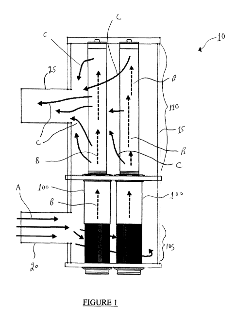
[0040] With reference to Figure 1, there is illustrated a fluid filter system
10 comprising a
housing 15 having an inlet 20 and an outlet 25. Disposed within housing 15 are
a pair of
identical fluid filter devices 100 which will be described in more detail
hereinbelow.
[0041] In use, a fluid to be filtered such (e.g., water) is fed into inlet 20
in the direction of arrows
A. Thus, the fluid passes through a coarse porous section 105 of each fluid
filter device 100
during which the fluid is subjected to coarse filtration.
[0042] Next, the fluid travels within each fluid filter device 100 in the
direction of hashed arrows
B. As shown, fluid travels from coarse porous section 105 of each fluid filter
device 100 to a
fine porous section 110 of each fluid filter device 100. Since the fluid is
under pressure, it
emanates from the fine porous section 110 of each fluid filter device 100 in
the direction of
arrows C. The fluid then emanates from fluid outlet 25.
[0043] Thus, fluid that is treated by fluid filter system 10 is subjected to
an initial filtering action
by coarse porous section 105 of each fluid filter device 100. This serves to
remove the larger
particles from the fluid. As will be apparent to those of skill in the art,
those larger particles
(possibly together with other fouling materials) may aggregate on the exterior
surface of coarse
porous section 105 of each fluid filter device 100.
[0044] The fluid is then subjected to a second filtering step whereby finer
particles still
contained in the fluid are filtered by fine porous section 110 of each fluid
filter device 100.
These fine particles may aggregate (possibly together with other fouling
marerials) on a interior
surface of fine porous 110 of each fluid filter device 100.
[0045] As will be described in more detail hereinbelow, an aspect of the
present invention relates
to a cleaning device for removing one or both of coarse particles (possibly
together with other
fouling marerials) that aggregate on the exterior of coarse porous section 105
of each fluid filter
device 100 and fine particles (possibly together with other fouling marerials)
which aggregate on
the interior surface of fine porous section 110 of each fluid filter device
100.
20
SUBSTITUTE SHEET (RULE 26)
WO 2012/021971 CA 02808323 2013-02-14PCT/CA2011/000928
[0046] In Figures 2-14, further details are provided on fluid filter device
100. It will be apparent
to those of skill in the art that housing 15 has been removed for clarity
purposes only.
[0047] Thus, with reference to Figures 2 and 3, there is shown the lower
portion of each fluid
filter device 100 in a so-called "in use" position. As shown, each fluid
filter device 100 is
affixed to an isolation flange 101 and a lower flanged 102.
[0048] Coarse porous section 105 of each fluid filter device 100 comprises an
axial filter screen
107 that is preferably in the form of a wedge wire filter. Preferably, the
axial filter screen has the
specifications described above for the first porous section of the present
fluid filter device.
[0049] Disposed above coarse porous section 105 of fluid filter device 100 is
a cleaning sleeve
115 that is connected to a linear drive 120 by a yolk 125. Disposed below
coarse porous section
105 of fluid filter device 100 is a T-valve 130. The operation of T-valve will
be described herein
below.
[0050] With particular reference to Figure 3, it will be seen that the
interior of coarse porous
section 105 of each fluid filter device 100 comprises a tie rod 108. The lower
portion of coarse
porous section 105 of fluid filter device 100 comprises an annular backwash
opening 111 defined
by an annular end portion 112. The distal edges of annular end portion 112 are
in sealing
abutment with a filter seal 113 disposed on the upper surface of T-valve 130.
[0051] T-valve 130 comprises a sliding portion 132 that is movable with
respect to a base
portion 134. T-valve element 130 is normally maintained in the position shown
in Figures 2 and
3 by a biasing element 136 (e.g., an elastomer spring, a metallic spring,
etc.).
[0052] As shown particularly in Figure 3, cleaning sleeve 115 comprises a
scraper element 117
for removing fouling materials from the exterior surface of axial filter
screen 107 of coarse
porous section 105. Preferably, scraper element 117 is in the form of a
polymer (e.g., elastomer)
scraper.
[0053] As described above, in normal use, fluid to be filtered will pass
through axial filter screen
107 of coarse porous section 105. After a period of time it is possible that
particulate or other
21
SUBSTITUTE SHEET (RULE 26)
WO 2012/021971 CA 02808323 2013-02-14PCT/CA2011/000928
fouling materials will aggregate on the exterior surface of axial filter
screen 107 of coarse porous
section 105. When it is desired to remove these fouling materials, linear
drive 120 is actuated to
move cleaning sleeve 115 toward T-valve 130 ¨ see Figures 4 and 5 which show
cleaning sleeve
115 being lowered toward T-valve 130.
[00541 Figures 6-8 illustrate fluid filter devices 100 wherein cleaning
sleeves 115 of each fluid
filter device 100 fully covers coarse porous section 105 while concurrently
actuating T-valve to
allow backwashing of fluid from the interior of fluid filter device 100.
[0055] Thus, as shown with particular reference to Figures 7 and 8, the distal
most edge of
cleaning sleeve 115 contacts the upper surface of T-valve 130 thereby pushing
downward sliding
portion 132 and compressing biasing element 136. The combination of these
actions serves to
separate annular end portion 112 of cleaning sleeve 115 from filter seal 113
of T-valve 130. This
serves to allow fluid contained in fluid filter device 100 to pass through
annular backwash
opening 111 and out of T-valve 130 in the direction of arrow D.
[0056] After the backwashing step has been completed, linear drive 120 is
reversed and cleaning
sleeve 115 is retracted away from T-valve 130. Biasing element 136 then moves
sliding portion
132 upward such that annular end portion 112 of cleaning sleeve 115 is
returned to a sealing
engagement position with filter seal 113 of T-valve 130. This also exposes
axial filter screen
107 of coarse porous section 105 to allow fluid to be filtered.
[0057] With reference to Figures 9-12, there is illustrated a portion of the
porous section 110 of
fluid filter device 100.
[0058] Fine coarse section 110 comprises an axial filter screen 109.
Preferably, axial filter
screen 109 has these specifications described above for the second porous
section of the present
fluid filter device.
[0059] An annular cleaning ring 140 is disposed on the outside of axial filter
screen 109.
Cleaning ring 140 is attached to a drive yolk 139 which serves to move
cleaning ring 140 along
the exterior of axial filter screen 109 ¨ see, for example, Figure 11 which
illustrates cleaning
rings 140 being moved along the exterior surface of axial filter screen 109.
22
SUBSTITUTE SHEET (RULE 26)
WO 2012/021971 CA 02808323 2013-02-14PCT/CA2011/000928
[0060] With particular reference to Figure 12, it can been seen that a line
141 is connected to
each annular cleaning ring 140. Line 141 supplies pressurized fluid (liquid or
gas) to annular
cleaning rings 140.
[0061] With particular reference to Figures 13 and 14, it can been seen that
annular cleaning ring
140 operates in a manner similar to a so-called "water knife". Thus, annular
cleaning ring 140
comprises an interior chamber having a fluid distribution channel 142, a fluid
flow transition 143
and a slit 144.
[0062] With particular reference to Figure 14, and as discussed above with
reference to Figure 1,
it is common to have particulate and other fouling materials 145 aggregate on
the interior surface
of axial filter screen 109. Fouling materials 145 may be removed in the
following manner.
[0063] A source of pressurized fluid (liquid or gas), preferably water, is fed
through line 141 into
flow distribution channel 142 of annular cleaning ring 140. The pressurized
fluid moves in the
direction of arrow E and exits slit 144 as shown to impinge on axial filter
screen 109 at a
relatively high pressure. This high pressure fluid blasts fouling material 145
as shown in circle
F. As drive yolk 139 is actuated to move annular cleaning ring 140 in the
direction of arrow G,
fouling materials 145 are continuously removed from the interior surface of
axial filter screen
109.
[0064] In a preferred embodiment cleaning rings 140 are actuated at the same
time as cleaning
sleeves 115 with the result that backwash of fluid from the interior of fluid
filter device 100
removes fouling materials 145 that have been dislodged from the interior
surface of axial filter
screen 109 by operation of cleaning rings 140. Alternatively, it is possible
to actuate cleaning
rings 140 when fluid filter device 100 is not in use ¨ e.g., as part of a
periodic maintenance
procedure.
[0065] While this invention has been described with reference to illustrative
embodiments and
examples, the description is not intended to be construed in a limiting sense.
Thus, various
modifications of the illustrative embodiments, as well as other embodiments of
the invention,
will be apparent to persons skilled in the art upon reference to this
description. For example,
23
SUBSTITUTE SHEET (RULE 26)
WO 2012/021971 CA 02808323 2013-02-14PCT/CA2011/000928
while the illustrated axial filter screen for use in the present fluid filter
device is a so-called
wedge wire filter it is possible to use other filters for the axial filter
screen ¨ e.g., mesh, screens,
sintered elements (e.g., made from brass, stainless steel and the like) and
the like. Further, while
the illustrated annular cleaning ring 140 comprises a continuous single,
annular slit 144, it is
possible to utilize a multiplicity of individual jets or nozzles. Still
further, while the illustrated
embodiment comprises a single line 141 connected to a single annular cleaning
ring 140, it is
possible to have one line 141 connected to a multiplicity of annular cleaning
rings 140 (e.g.,
serial connection). It is therefore contemplated that the appended claims will
cover any such
modifications or embodiments.
100661 All publications, patents and patent applications referred to herein
are incorporated by
reference in their entirety to the same extent as if each individual
publication, patent or patent
application was specifically and individually indicated to be incorporated by
reference in its
entirety.
24
SUBSTITUTE SHEET (RULE 26)