Note: Descriptions are shown in the official language in which they were submitted.
METHOD AND APPARATUS FOR DEPLOYING AND SUPPORTING A FLEXIBLE
OBJECT
FIELD OF THE INVENTION
This invention relates to a method and apparatus for deploying and supporting
a flexible object.
In particular this invention relates to flying or hanging of flexible objects
such as flags, banners,
visual display or advertising material, festive lighting, or decorations. More
particularly, the
invention relates to a method and apparatus for deploying a flexible object
such as a flag by
moving or raising the object from a first to a second location, and supporting
the object at the
second location.
Flags, banners, pennants, burgccs, colours, ensigns, jacks and standards, and
the like, are to be
understood as included by either one of the terms 'flag' or 'banner', and the
corresponding plural
forms, when used in this specification which uses these terms generically. The
term 'flexible
object' as used herein is to be understood to mean any object where the object
as a whole is
substantially flexible, and includes objects such as strings of lights that
have rigid portions
(lights) connected by flexible portions (wires).
BACKGROUND
Flags have been known for many millennia, and are typically flown from an
upstanding or
outstanding staff, or flagpole. In general, flags have a 'hoist' edge at which
the flag is supported.
Flags can be flown with the hoist edge substantially vertical, such as when
the flag is flown from
a vertical flagpole, or inclined or horizontal. In the latter configurations,
the suspended flag can
remain unfurled, even in the absence of wind or other air movement.
In one common arrangement, flags are hoisted up a flagpole by attachment of
the upper end of
the hoist edge of the flag to a clip on one bight of a halyard which has been
previously configured
to run over a sheave in an enclosed pulley at a truck at or near the head of
the flagpole. The flag is
then raised by pulling down on the other bight of the halyard.
The halyard system is vulnerable to misalignment or jamming of the halyard at
the sheave. It is
generally only suitable for use in straight, upright flagpoles, not in curved
or irregularly shaped
flagpoles. Furthermore, if one end of the halyard is inadvertently released,
it can rise and the clip
can lodge at the masthead pulley or, and particularly if no clip is used, one
bight of the halyard
may rise and pass over the sheave. Before another flag can be raised up the
pole, the halyard clip
1
CA 2861035 2018-07-26
CA 02861035 2014-08-19
WO 2013/089566
PCT/NZ2012/000237
must be retrieved from the top of the pole or the halyard re-threaded over the
masthead sheave.
This usually requires the use of a ladder or cherry-picker or the like to gain
access to the elevated
sheave.
Furthermore, the noise of a halyard, oscillated by wind to strike repetitively
against the flagpole,
can be annoying.
In other common arrangements, flags or banners are often deployed without
halyards or
sheaves, being fixed directly to attachment points on flagpoles, walls, or
other constructions.
This is the most common method for attaching curved or irregularly shaped
flags or banners to
curved supports.
Banners may also be provided with large hems or sleeves that are open at at
least one end, and
that can be slipped over the end of an upright or inclined or horizontally
cantilevered staff,
banner bracket arm, or flagpole. In these, and other, arrangements, the flags
and banners are
usually flown from elevated positions to improve their visibility and impact.
The fitting of a flag
to any elevated support often requires the use of a ladder, cherry-picker or
the like to provide
safe access to the elevated position. For example, hemmed banners flown in
public spaces are
often deployed over flagpoles cantilevered from streetlight standards. Not
only is a ladder or
cherry-picker often required, but often traffic or safety control measures are
mandated by
authorities when the flags are to be installed and flown over roadways or
other public spaces.
It can therefore be time consuming and expensive to replace numbers of flags
or banners, such
as when they have become worn or outdated.
One existing system for deploying a flag or banner from ground level comprises
having the flag
or banner connected along a hoist edge of the flag or banner to a push-rod
that is, in turn,
slidable relative to a preferably straight support member. To use that system
to mount a banner
or flag on a curved support, the banner or flag must be elastic to prevent
jamming of the push-
rod in the support or to prevent the banner or flag from tearing during
deployment. Flags or
banners made from elastic material are generally more expensive, more
difficult to procure and
print, and less durable than those made from traditional inelastic materials.
Durability is highly
desirable for flags or banners that are to be hung outdoors as they will be
subject to various
weather conditions.
2
CA 02861035 2014-08-19
WO 2013/089566
PCT/NZ2012/000237
It is an object of at least preferred embodiments of the present invention to
provide an
apparatus or method of flying a flag or other flexible object that helps
mitigate against at least
some of the shortcomings of the prior art, or at least to provide the public
with a useful choice.
SUMMARY OF THE INVENTION
A first aspect of the present invention provides an apparatus for deploying
and supporting a
flexible object. The apparatus comprises: an elongate support comprising a
longitudinal first
guide, an elongate flexible member longitudinally slidable relative to the
first guide, a first
connector, connected to the flexible elongate member and adapted to be
attached to the flexible
object, a longitudinal second guide, and at least one sliding connector
longitudinally slidable
relative to the second guide and adapted to be attached to the flexible
object. The flexible
elongate member is adapted to be pushed along the first guide via an
externally applied
longitudinal force, transferred as a compressive internal force along the
flexible member, to
move the flexible object from a first position to a deployed position.
The deployed position may be elevated relative to the first position.
The flexible member preferably comprises the longitudinal second guide, and
preferably at least a
major part of the flexible member is resilient. The flexible member may be a
rod, tube, band,
strip, or other suitable elongate member.
In an embodiment, the apparatus comprises plurality of sliding connectors. One
of the sliding
connector(s) may comprise a trailing sliding connector having an engagement
feature and the
support member may comprise a latch or stop configured to engage the
engagement feature as
the flexible object is moved to the deployed position. The first connector may
comprise a
leading connector that is fixed to the flexible member. Preferably there are a
plurality of sliding
connectors between the first connector and the trailing connector.
The support may comprise a curved portion and may be substantially rigid.
Preferably the
support comprises a first portion and a second portion and the angle between
the first support
portion and the second support portion is in the range of 80 to 150 degrees.
In one
embodiment, the angle between the first support portion and the second support
portion is in
3
CA 02861035 2014-08-19
WO 2013/089566
PCT/NZ2012/000237
the range of about 90 to about 120 degrees. In one embodiment, the angle
between the first
support portion and the second support portion is about 90 degrees. In an
alternative
embodiment, the angle between the first support portion and the second support
portion is
about 130 degrees.
The support may comprise a stop to limit sliding of the flexible member along
the first guide,
such that an end of the flexible member abuts the stop when the flexible
object is in the
deployed position. The support may be configured to be attached to a fixed
construction or may
itself be a fixed construction.
In an embodiment, the first guide comprises a track on the support. The first
guide may
comprise an elongate passage in the support having a longitudinal slot
extending substantially
along the length of the passage for receiving the flexible member.
In an embodiment, the second guide comprises a longitudinal track extending
along at least part
of the length of the flexible member. Alternatively, the support may comprise
the second guide.
In another embodiment, the flexible member may comprise the second guide and
the sliding
connector(s) define a channel for receiving the flexible member.
The flexible object may be a flag or banner.
A second aspect of the present invention provides a flexible object for
deploying and supporting
on the apparatus according to the first aspect. The flexible object has a
hoist edge with the first
connector connected to a leading portion of the hoist edge, and the sliding
connector(s)
connected to a trailing portion of the hoist edge. At least a portion of the
hoist edge is curved.
In one embodiment, the first connector is connected to a leading end of the
hoist edge. The
sliding connectors are preferably spaced apart. The flexible object may
comprise a trailing
connector with an engagement feature configured to engage with a catch or stop
on the support.
The trailing connector may be connected to a trailing end of the hoist edge.
Preferably the hoist edge comprises a first edge portion and a second edge
portion that, in a
non-flexed configuration, is oriented in the range of 80 to 150 degrees to the
first edge portion.
In one embodiment, the second hoist edge portion is oriented in the range of
about 90 to about
130 degrees to the first edge portion when the flexible object is in a non-
flexed configuration. In
4
CA 02861035 2014-08-19
WO 2013/089566
PCT/NZ2012/000237
one embodiment, the second hoist edge portion is at about 90 degrees to the
first edge portion
when the flexible object is in a non-flexed configuration. In an alternative
embodiment, the
second hoist edge portion is at about 130 degrees to the first edge portion
when the flexible
=
object is in a non-flexed configuration.
The flexible object may be a flag or banner.
A third aspect of the present invention provides a method of deploying and
supporting a flexible
object. The method comprises: providing an elongate support having a first
guide, attaching a
first connector to a leading portion of the flexible object, attaching at
least one sliding connector
to a trailing portion of the flexible object, slidably connecting the sliding
connector(s) to a guide
on the support or the elongate flexible member such that the sliding
connector(s) are
longitudinally slidable relative to the guide, attaching the first connector
to a leading portion of
an elongate flexible member, and slidably connecting the flexible member to
the first guide of
the support, and pushing the flexible member along the support by applying a
longitudinal force
to a trailing portion of the flexible member, the force being directed towards
the leading portion
of the flexible member and transferred as a compressive internal force along
the flexible object
to move the flexible member and thereby the flexible object to a deployed
position.
Preferably at least a portion of the support is curved and the flexible member
is resilient.
In one embodiment, the flexible member comprises the guide for the sliding
connector(s), and as
the flexible member is pushed to the deployed position, the sliding
connector(s) slide(s)
longitudinally relative to the flexible member. In an alternative embodiment,
the support
comprises the guide for the sliding connector(s), and as the flexible member
is pushed to the
deployed position, the sliding connector(s) slide(s) longitudinally relative
to the support.
The support may comprise a stop or catch and one of the sliding connector(s)
may comprise a
trailing sliding connector with an engagement feature that is engagable with
the stop or catch; the
method according to the third aspect comprising the step of engaging the
trailing sliding
connector with the stop or catch as the flexible member is pushed to the
deployed position.
The method may further comprise securing the flexible member relative to the
support so that
the flexible object is supported in the deployed position.
5
CA 02861035 2014-08-19
WO 2013/089566
PCT/NZ2012/000237
Preferably the support comprises a first portion and a second portion and the
angle between the
first support portion and the second support portion is in the range of 80 to
150 degrees. In one
embodiment, the angle between the first support portion and the second support
portion is in
the range of about 90 to about 130 degrees. In one embodiment, the angle
between the first
support portion and the second support portion is about 90 degrees. In an
alternative
embodiment, the angle between the first support portion and the second support
portion is
about 130 degrees. The flexible object may comprise a flag or banner.
To those skilled in the art to which the invention relates, many changes in
construction and
widely differing embodiments and applications of the invention will suggest
themselves without
departing from the scope of the invention as defined in the appended claims.
The disclosures
and the descriptions herein are purely illustrative and are not intended to be
in any sense
limiting. Where specific integers are mentioned herein which have known
equivalents in the art
to which this invention relates, such known equivalents are deemed to be
incorporated herein as
if individually set forth.
As used herein the term "(s)" following a noun means the plural and/or
singular form of that
noun.
The invention consists in the foregoing and also envisages constructions of
which the following
gives examples only.
BRIEF DESCRIPTION OF THE DRAWINGS
The present invention will now be described by way of example only and with
reference to the
accompanying drawings in which:
Figure 1 shows a diagrammatic side view of a flag apparatus according to an
embodiment
of the present invention, with the flag in a lowered position;
Figure 2 shows a diagrammatic side view of the apparatus of figure 1, with the
flag
between the lowered position and a deployed position;
Figure 3 shows a diagrammatic side view of the apparatus of figures 1 and 2,
with the
flag in a deployed position;
Figure 4 is an exploded perspective view of a portion of a first embodiment of
the
invention, showing the connection between the elongate flexible member and the
connectors;
6
CA 02861035 2014-08-19
WO 2013/089566
PCT/NZ2012/000237
Figure 5 is an exploded perspective view of the embodiment of Figure 4 showing
the
connection between the flexible member and the support;
Figure 6 is a perspective view of the assembled apparatus according to the
embodiment
of Figures 4 and 5;
Figure 7 is a section view taken through section line AA shown in Figure 6;
Figure 8 is an exploded perspective view of a portion of a second embodiment
of the
invention, showing the connection between the elongate flexible member and the
connectors;
Figure 9 is an exploded perspective view of the embodiment of Figure 8 showing
the
connection between the flexible member and the support;
Figure 10 is a perspective view of the assembled apparatus according to the
embodiment
of Figures 8 and 9;
Figure 11 is a section view taken through section line BB shown in Figure 10;
Figure 12 is an exploded perspective view of a portion of a further embodiment
of the
invention, showing the connection between the elongate flexible member and the
connectors;
Figure 13 is an exploded perspective view of the embodiment of Figure 12
showing the
connection between the flexible member and the support;
Figure 14 is a perspective view of the assembled apparatus according to the
embodiment
of Figures 12 and 13;
Figure 15 is a section view taken through section line CC shown in Figure 14;
and
Figure 16 is an exploded perspective view of the apparatus of Figure 1, also
showing an
bracket arrangement for connecting the apparatus to a fixed construction.
DETAILED DESCRIPTION OF A PREFERRED EMBODIMENT
Referring to the figures, it will be appreciated that the invention may be
implemented in various
forms and modes. The following description of a preferred embodiment of the
invention is
given by way of example only.
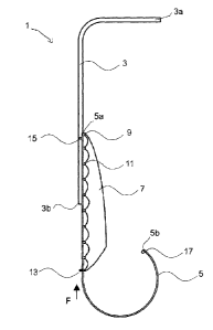
Figures 1 to 16 show an apparatus 1 for moving a flag 7 between a relatively
low position to a
higher, deployed position. Figure 1 shows the flag at the lower position
whereas Figure 3 shows
the flag raised and flying at the higher deployed position. Figure 2 shows the
flag at an
intermediate position between the lowered position and the higher deployed
position.
The apparatus 1 comprises an elongate support 3 comprising a longitudinal
first guide 4 and an
elongate flexible member 5 that is slidable relative to the support 3 along
the first guide 4. The
7
CA 02861035 2014-08-19
WO 2013/089566
PCT/NZ2012/000237
first guide 4 may be best appreciated from the section view shown in Figure 7
Figures 11 and 15
are cross-sectional views showing the first guides 104, 204 for the
alternative embodiments of
figures 8-10 and 12-14, respectively.
The flexible member 5 is separable from the support 3 and has a profile or
feature for
cooperation with the first guide 4. In one embodiment, such as that shown in
Figures 7-11 and
12-15, the first guide 4 may comprise a track in the support 3, 203 for
receiving the flexible
member 5, 205 or a portion of the flexible member. In the embodiment of Figure
7, the track 4
comprises a channel or passage with a front slot and two side slots 4a for
receiving longitudinal
side flanges 5c on the flexible member 5. In an alternative embodiment, for
example that shown
in Figures 8 to 11, the track 104 comprises a round passage with a
longitudinal front slot 104a
for receiving a rod-like flexible member having a diameter that is less than
the width of the front
slot 104a. Alternatively, the flexible member 5 may comprise a track or
channel for receiving a
longitudinal portion, such as a longitudinal flange or protrusion, of the
support 3.
A plurality of connectors 9, 11, 13; 109, 111, 113; 209, 211, 213 are attached
to a hoist edge of
the flag 7 from which the flag is hoisted. Referring to the embodiment of
Figures 1 to 7, a first
leading connector 9 is attached to a leading portion of the hoist edge of the
flag 7 and a leading
or top portion of the flexible elongate member 5. The leading connector 9 is
preferably fixed to
the leading end 5a of the flexible member 5 and may slide directly along the
first guide 4. The
leading connector 9 may alternatively be connected to the flexible member 5 at
a distance from
the leading end 5a of the flexible member. The connection between the leading
connector 9 and
the flexible member 5 is preferably fixed but may be any connection where
longitudinal
movement of the leading connector 9 is restricted or limited in the direction
away from the
leading end 5a of the flexible member, for example by a stop or fixed
connection. The leading
portion 5a of the flexible member 5 may comprise a feature or opening for
removably receiving
the leading connector 9.
A plurality of sliding connectors 11, 13 are fixedly attached to and spaced
along the hoist edge of
the flag 7 on a trailing side of the first leading connector 9. There may be
1, 2 or more sliding
connectors 11, 13. The sliding connectors 11, 13 may each be attached directly
or indirectly to
the flag. The connectors may be permanently fixed to the flag, for example
stitched to the flag,
or alternatively may be removably attachable to the flag by a hook, clip, or
catch, for example.
8
CA 02861035 2014-08-19
WO 2013/089566
PCT/NZ2012/000237
In the embodiment shown in Figures 4 to 7, the flexible member 5 defines a
longitudinal second
guide 6 in the form of a central track, for slidably receiving the sliding
connectors 11, 13 (one of
which is shown in Figure 7). The second guide 6 is configured to be
substantially parallel to the
first guide 4 when the apparatus is assembled. The flexible member 5 is
therefore slidable
relative to the support 3 and the sliding connectors 11, 13 are in turn
independently slidable
relative to the flexible member 5.
In the embodiment shown in Figures 8 to 11, the flexible member 105 itself
forms the second
guide 106, and the sliding connectors 111, 113 each define a channel or
passage for receiving the
flexible member. The sliding connectors therefore slide directly in the first
guide channel 104 of
the support 103. The flexible member 105 is slidable relative to the support
103 and the sliding
connectors 11, 13 are in turn independently slidable relative to both the
flexible member 105 and
the support 103.
The second guide 6 may alternatively be provided by the support as shown in
Figures 12 to 15,
for example by way of a track 206 on the support 203 for receiving the sliding
connectors 211,
213, or alternatively the second guide may be a longitudinal flange or
protrusion, on the support
and the sliding connectors may each define a channel, for example, for
receiving the second
guide.
One sliding connector 13, 113, 213 is a trailing connector attached to the
most trailing portion of
the hoist edge, preferably at a lower corner of the flag, such that the other
sliding connectors are
between the first leading connector 9 and the trailing connector 13. The
trailing connector 13
comprises an engagement feature 13a. In the embodiment shown in the figures,
the engagement
feature 13a is a lip, flange or projection on the connector 13, 113, 213 which
extends along the
front or side of the support 3, 103, 203. The support 3, 103, 203 has a
corresponding catch or
stop 15, 115, 215 fixed to the support configured to engage the trailing
connector 13 as the flag
is raised.
Figure 1 shows the lower end of the elongate member extending from the lower
end of the
support 3. To deploy the flag 7 on the apparatus, the flag 7 is first attached
to the flexible
member 5 via the first leading connector 9. Depending on the embodiment, the
flag is also
attached to the flexible member 5 or the support 3 by the sliding connectors
11, 13. The sliding
connectors are inserted into the guide channel 6 in the flexible member 5 and
the leading
9
CA 02861035 2014-08-19
WO 2013/089566
PCT/NZ2012/000237
connector is fixed to the leading end 3a of the support, so that the sliding
connectors can slide
along the guide 6.
The upper end 5a of the elongate flexible member 5, is then fed into a lower
end 3b of the guide
channel 4 in the support 3. The lower end of the support 3b may be open at a
local widening of
the guide slot or channel or opening, e.g. by bending outward or cutting away
the edges of the
channel to provide open access for insertion of the flexible member into the
first guide 4.
To raise the flag, the flexible member is pushed along the first guide 4 by
applying a longitudinal
force to a trailing portion of the flexible member 5. The longitudinal force
is externally applied
and directed substantially as indicated by the arrow F in Figures 1 and 2,
towards the leading
portion of the flexible member, to slide the flexible member upwards, and with
it the attached
flag from the leading connector 9.
The force is transferred as an internal compression force along an
intermediate portion of the
flexible member 5. The flexible member 5 is preferably resilient and
substantially incontractible
and resists the internal compression force established along its length such
that one end of the
flexible member 5 can be pushed to move the other end, to which the flag 7 is
connected by the
leading connector 9.
The flexiblitiy of the flexible member 5 allows it to be curved or coiled, as
shown in Figure 1.
This is particularly advantageous in cases where the lower end of the support
3 is too close to a
ground or floor level, leaving insufficient room to align a rigid straight
elongate member for
cooperation with the first guide. As the flexible member 5 is slid up the
first guide 4, the coiled
lower end 5b of the flexible member 5, is gradually uncoiled. The pushing and
uncoiling are
continued until the flag 7 is in a raised position, such as is shown in Figure
3.
The support 3 is preferably curved and its curvature may vary along its
length. For example, the
support shown in the figures has two straight portions at 900 to each other,
connected by a
curved corner. Alternatively, the straight portions may be at more or less
than 90 to each other.
For example, in some embodiments, the angle between the straight portions may
be in the range
of 80 and 130 , preferably about 90 to about 130 . For example, in one
alternative
embodiment the two straight portions are at about 130 to each other. As a
further alternative,
a lower portion of the support 3 may be straight and the whole upper portion
curved. The
CA 02861035 2014-08-19
WO 2013/089566
PCT/NZ2012/000237
flexibility of the elongate flexible member 5 allows it to bend to accommodate
the curve or
change in curvature, as the flexible member 5 is moved along the curved
support 3.
As the flexible member 5 is pushed along the support 3 to raise the flag 7,
the sliding connectors
11, 13 can slide relative to each other (and relative to leading connector 9)
to accommodate
changes in curvature, thereby allowing the flag to gather as necessary. This
means the flag,
banner or other flexible object isn't placed under tension that could tear the
flag, and reduces the
likelihood of the flexible member jamming relative to the first guide from
tension in the flag
being transferred to the flexible member. This makes the present invention
suitable for flags,
banners or other flexible objects made from relatively inelastic materials.
In one embodiment the flag 7 is flown at a curved portion of the support 3, as
shown in Figure
3, and the hoist edge of the flag is preferably shaped with a curve
corresponding to the curve of
the support 3.
As the flag 7 is raised to the deployed position, the engagement feature 13a
on the most trailing
connector 13 engages with the stop or catch 15 on the support 3, preventing
that connector
from being raised any further. Once the trailing connector 13 is engaged,
further sliding of the
flexible member 5 along the first guide 4 causes the flag or banner to
tension, preferably until the
flag or banner is taut, as shown in Figure 3 where the flag 7 is raised and
deployed.
In the embodiment shown in the figures, the flexible member 5 is substantially
the same length
as the elongate support 3. However, the flexible member 5 may alternatively be
longer or
shorter than the support 3. The upper end 3a of the elongate support may
comprise a stop 19
which the flexible member abuts when the flag 7 is in the deployed position.
In this way, the flag 7 can be raised from a relatively low level position,
such as within easy reach
of a person standing safely at ground or floor level, to a relatively high
elevated position well
above the reach of persons at the lower level. A flag, banner or other
flexible object can thus be
raised to a relatively high level without using the conventional flag and pole
arrangement with a
halyard running over a sheave fitted at the higher level, or without needing
to lift a person up to
the high level, such as on a cherry picker or ladder. =
11
CA 02861035 2014-08-19
WO 2013/089566
PCT/NZ2012/000237
The flag 7 is lowered by reversal of the procedure, by pulling on the flexible
member 5 to
remove it from the support 3, without requiring anybody to access the upper
level. The flag is
pulled down by the upper leading connector 9. Typically the flag will gather
as it is lowered and
the leading connector 9 slides towards the sliding connectors 11. The flexible
member 5 is
preferably substantially inextensible, allowing the flag to be easily lowered
by pulling down on
the flexible member 5.
The first guide 4 on the support constrains at least a major portion of the
flexible member 5 to
follow the general shape of the support 3, thereby preventing the flexible
member 5 from
bending excessively when under compression, and allowing the flag to be
raised. In one
advantageous embodiment, the flexibility of the flexible member 5 allows it to
readily bend, not
only to be moved through any curvature of the constraint, but also to be
coiled up into a
relatively flat compact form for transportation.
The resilience of the flexible member 5 may make the flexible member alone
insufficiently stiff
to support the flag 7 at the deployed position. However, the flexible member 5
can support the
flag 7 at the deployed position when the flexible member is constrained by the
first guide 4 of
the elongate support 3.
The support 3 is preferably rigid and may itself be fixed and free standing or
it may be supported
by attachment to a fixed construction (not shown in the figures), such as a
pole, streedamp
standard, or the exterior or interior wall of a building, for example. The
support 3 may comprise
flanges, tabs or other features by which it can be attached to a fixed
construction by an adhesive
or by fasteners such as screws, nails, staples, rivets, or strapping. Figure
16 shows an example of
one possible method of attachment to an upright construction (not shown) using
a bracket
arrangement 20.
Two or more flags may be attached to a common elongate flexible member 5
supported as
described above.
In a preferable arrangement, the elongate flexible member 5 is made as one
length of a flexible
plastics material. PVC has been found to be particularly suitable. Other
suitable materials
include metals, and resins or plastics, with or without reinforcement by
fibres such as glass or
carbon for example. The flexible member 5 may be a tube or rod and may be
extruded or
12
CA 02861035 2014-08-19
WO 2013/089566
PCT/NZ2012/000237
pultruded from plastics or resin materials, optionally reinforced with fibres,
such as glass or
carbon fibres.
When the flag, flags or other flexible object(s) have been raised and are at
the elevated location
ready for flying, the lower end of the flexible member 5 can be fixed or
secured to the constraint
to hold the flexible member and the flag 7 or other flexible object(s) in that
position. The fixing
can be by any suitable means, for example by a pin inserted through the
tubular constraint at a
point below, or through, the lower end portion of the flexible member.
In a preferred embodiment the trailing end comprises a locking device 17 for
securing the
flexible member 5 to the support 3. In one embodiment the locking device
comprises a resilient
latch for engaging a detent on the support. To disengage the flexible member
from the support
a tool such as a screwdriver may be used to pry the latch out of the detent.
Alternatively the
locking device 17 may comprise a lock or a tamper resistant screw pin to
reduce the likelihood of
unauthorised interference with, or removal of, the flag.
The foregoing describes the invention with reference to a preferred
embodiment. Alterations
and modifications as will be obvious to those skilled in the art are intended
to be incorporated
within the scope of the invention as defined in the accompanying claims. For
example, although
the preferred embodiments are generally described as for raising a flag from a
low level to a
higher level, the invention has equal applicability to the movement of a flag
from a first location
to a second location that is remote from the first, such as below, or
horizontally spaced from, the
first location.
The invention can be applied to flags and banners or other substantially
flexible objects other
than flags or banners. For example, the invention can be applied to flags and
banners made
from plastics, such as polyvinyl chloride (PVC), to flags, banners and posters
made from paper
or paper-based materials, or to festive decorations or strings of lights, or
projection screens.
Preferred embodiments of the invention have been described by way of example
only and
modifications may be made thereto without departing from the scope of the
invention.
The invention is particularly advantageous where there is an ongoing need for
objects to be
raised to, supported at, and lowered from, elevated positions on curved
supports and that would
13
CA 02861035 2014-08-19
WO 2013/089566
PCT/NZ2012/000237
otherwise require ladders, scaffolding, cherry-pickers, or the like. Once
installed, the invention
allows for the successive deployment of objects at elevated positions by
personnel remaining at
floor or ground level.
The term 'comprising' as used in this specification and claims means
'consisting at least in part
of', that is to say when interpreting statements in this specification and
claims which include that
term, the features, prefaced by that term in each statement, all need to be
present but other
features can also be present.
14