Note: Descriptions are shown in the official language in which they were submitted.
CA 02894983 2015-06-22
POLYMORPHIC SURFACE SYSTEMS AND METHODS
TECHNICAL FIELD
[0002] The present disclosure relates to polymorphic surface systems, that is,
to systems
having an adjustable surface which can assume a variety of shapes, and to
related methods.
BACKGROUND
[0003] Computer imaging technology has advanced dramatically over the past
several
decades. Computers can now capture detailed three-dimensional image
information, such as
from laser scanning, medical imaging devices and many other sources, and can
also generate
three-dimensional image information. However, computers have conventionally
been limited
in their ability to present such three-dimensional data. Often such data is
presented in two-
dimensional form on a screen, where much of the richness of the data may be
lost.
[0004] More recently, three-dimensional printing technology has enabled
computers to
generate real three-dimensional models that can be made the subject of not
only visual but
also tactile examination. While three-dimensional printing can provide
considerable
advantages, it necessarily consumes material and produces waste if the printed
object is
ultimately unwanted. Relying solely on three-dimensional printing to enable
computers to
express three-dimensional data is analogous to a computer which, for two-
dimensional data,
has a printer but no monitor.
SUMMARY
[0005] The present disclosure describes an electronically controllable
polymorphic surface
system, that is, a system with an adjustable physical surface which can
dynamically assume a
- 1 -
CA 02894983 2015-06-22
variety of transitory and/or persistent topographical shapes to represent
three-dimensional
information.
[0006] In one aspect, a polymorphic surface system comprises a guide structure
having a
plurality of individual cavities formed therein, and a plurality of surface
contour elements.
Each surface contour element is received in a respective one of the individual
cavities for
reciprocal substantially linear motion therein, and each of the surface
contour elements has at
least one electrically conductive path thereon. Each of the cavities has a
magnetic field
extending thereacross. Electrical contacts are associated with each cavity,
and for each
cavity, the electrical contacts comprise at least one first side electrical
contact and at least one
second side electrical contact. The first side electrical contact(s) are
electrically isolated from
the second side electrical contact(s) except for the electrically conductive
path on the
respective surface contour element in the cavity. The electrically conductive
path(s) on the
respective surface contour element in each cavity maintain electrical
communication between
the first side electrical contact(s) and the second side electrical contact(s)
over a range of the
reciprocal substantially linear motion of the respective surface contour
element within the
respective cavity. For each cavity, the first side electrical contact(s), the
electrically
conductive path(s) on the respective surface contour element in the cavity and
the second side
electrical contact(s) cooperate to form a circuit segment of an electrical
circuit across the
cavity. The electrical circuit includes a controller adapted to address the
circuit segments to
selectively apply current to, and remove current from, one or more selected
circuit segments.
Upon application of current to a selected circuit segment, the applied current
interacts with the
magnetic field across the respective cavity to generate a Lorentz force that
drives substantially
linear motion of the respective surface contour element within the respective
cavity.
[0007] In a preferred embodiment, the magnetic field across each cavity is
substantially
perpendicular to the reciprocal substantially linear motion of the respective
surface contour
element within the respective cavity and current flowing through the circuit
segment is
substantially perpendicular to the magnetic field across the cavity and is
also substantially
perpendicular to the reciprocal substantially linear motion of the respective
surface contour
element within the respective cavity.
- 2 -
CA 02894983 2015-06-22
[0008] The controller may be adapted to selectively control a current applied
to a selected one
of the circuit segments. The controller may be adapted to detect a linear
position of each
surface contour element relative to its respective cavity, and may be further
adapted to detect
resistance to linear motion of individual ones of the surface contour elements
by comparing
an expected rate of linear motion to an actual rate of linear motion. The
controller may be
further adapted to detect induced current across each circuit segment, wherein
the induced
current is induced by movement of the surface contour element under external
force.
[0009] In one embodiment, a single magnetic field extends across all of the
cavities. In such
an embodiment, the guide structure may comprise a magnetized ferromagnetic
material to
generate the single magnetic field. In another embodiment, a plurality of
individual magnets
are be arranged to provide each cavity with its own magnetic field. In one
such embodiment,
the individual magnets are internal to the surface contour elements. In
another such
embodiment, the individual magnets may be electromagnets.
[0010] In some embodiments, the cavities and the surface contour elements
received therein
are arranged in a regular grid.
[0011] Preferably, each surface contour element has a respective length, width
and thickness,
the length being measured parallel to the reciprocal substantially linear
motion of the
respective surface contour element, with the length of each surface contour
element being
substantially greater than its width and the width of each surface contour
element being
substantially greater than its thickness.
[0012] In some embodiments, each surface contour element has a head having a
generally
planar superior surface and the heads of the surface contour elements
cooperate to form a
polymorphic surface.
[0013] The surface contour elements may comprise a magnetic material.
[0014] The surface contour elements may be arranged in the cavities to move
substantially in
parallel with one another.
-3 -
CA 02894983 2015-06-22
[0015] The polymorphic surface system may further comprise a resilient surface
layer over
the surface contour elements.
[0016] In some embodiments, the cavities are in valve-governed fluid
communication with a
fluid source for selectively introducing fluid into the cavities and sealing
the fluid within the
cavities to support the surface contour elements in the cavities after
discontinuing the applied
current, and withdrawing the fluid from the cavities to release the surface
contour elements.
[0017] In a further aspect, a polymorphic surface system comprises a guide
structure, a
plurality of individual cavities formed in the guide structure and a plurality
of surface contour
elements. Each surface contour element is received in a respective one of the
individual
cavities for reciprocal substantially linear motion therein and each of the
surface contour
elements generates a respective magnetic field. Respective circuit segments of
an electrical
circuit extend across each cavity, and the electrical circuit includes a
controller adapted to
individually address the circuit segments to selectively apply current to, and
remove current
from, one or more selected circuit segments. Upon application of current to a
selected one of
the circuit segments, the applied current interacts with the respective
magnetic field to
generate a Lorentz force that drives substantially linear motion of the
respective surface
contour element within the respective cavity.
[0018] Preferably, the magnetic field generated by each surface contour
element is
substantially perpendicular to the reciprocal substantially linear motion of
the respective
surface contour element within the respective cavity and current flowing
through the circuit
segment is substantially perpendicular to the magnetic field and is also
substantially
perpendicular to the reciprocal substantially linear motion of the respective
surface contour
element within the respective cavity.
[0019] The individual magnets may be internal to the surface contour elements.
[0020] In another aspect, a method for dynamically forming a surface
topography comprises
applying at least one magnetic field across a plurality of movable surface
contour elements
and selectively passing a current through the at least one magnetic field
adjacent selected ones
of the surface contour elements, so that for each selected surface contour
element, the current
- 4 -
CA 02894983 2015-06-22
interacts with the magnetic field to generate a Lorentz force that drives
guided substantially
linear motion of the respective surface contour element. Preferably, the
current is
substantially perpendicular to the at least one magnetic field and the guided
substantially
linear motion of the respective selected surface contour element is
perpendicular to both the at
least one magnetic field thereacross and to the current. Preferably, the
surface contour
elements are individually moveable and individually selectable for application
of current to
generate movement.
[0021] The method may further comprise supporting the surface contour elements
in position
after removing the current.
[0022] The method may further comprise controlling a current passed through
the at least one
magnetic field adjacent each selected surface contour element to control an
amount of guided
substantially linear motion of that selected surface contour element.
[0023] The magnetic field may be a single magnetic field, and selectively
passing a current
through the at least one magnetic field adjacent selected individual ones of
the surface contour
elements may comprise selectively applying the current across the selected
individual ones of
the surface contour elements.
[0024] The magnetic field may be a plurality of individual magnetic fields,
with each
individual magnetic field being generated by a respective surface contour
element, and
selectively passing a current through the at least one magnetic field adjacent
selected
individual ones of the surface contour elements may comprise carrying a
current past the
selected individual ones of the surface contour elements.
BRIEF DESCRIPTION OF THE DRAWINGS
[0025] These and other features will become more apparent from the following
description in
which reference is made to the appended drawings wherein:
FIGURE lA is a top isometric view of a first exemplary polymorphic surface
system with the
polymorphic surface thereof arranged in a generally planar configuration;
- 5 -
CA 02894983 2015-06-22
FIGURE 1B is a bottom isometric view of the polymorphic surface system of
Figure 1A;
FIGURE 1C is a top plan view of the polymorphic surface system of Figure 1A;
FIGURE 1D is a first side elevation view of the polymorphic surface system of
Figure 1A;
FIGURE lE is a bottom plan view of the polymorphic surface system of Figure
1A;
FIGURE 1F is a second side elevation view of the polymorphic surface system of
Figure 1A;
FIGURE 1G is a top isometric view of the polymorphic surface system of Figure
lA with the
polymorphic surface thereof arranged in a non-planar configuration;
FIGURE 1H is a bottom isometric view of the polymorphic surface system of
Figure lA with
the polymorphic surface thereof arranged in a non-planar configuration;
FIGURE 2A is a side elevation view of an exemplary surface contour element of
the
polymorphic surface system of Figure 1A;
FIGURE 2B is a cross-sectional view of the surface contour element of Figure
2A, taken
along the line 2B-2B in Figure 2A;
FIGURE 2C is a cross-sectional view of the surface contour element of Figure
2A, taken
along the line 2C-2C in Figure 2A;
FIGURE 2D is a detail view of a portion of Figure 2C;
FIGURE 2E is a top isometric view of the surface contour element of Figure 2A;
FIGURE 2F is a bottom isometric view of the surface contour element of Figure
2A;
FIGURE 3A is a side elevation view showing a single surface contour element
received
within a cavity in a portion of a guide structure of the polymorphic surface
system of Figure
1A;
- 6 -
CA 02894983 2015-06-22
FIGURE 3B is a cross-sectional view of the surface contour element and guide
structure
portion of Figure 3A, taken along the line 3B-3B in Figure 3A;
FIGURE 3C is a detail view of a portion of Figure 3B;
FIGURE 3D is a top isometric view of the surface contour element and guide
structure
portion of Figure 3A, schematically showing interconnection with a controller;
FIGURE 4A is a top isometric view of the guide structure of the polymorphic
surface system
of Figure 1A;
FIGURE 4B is a detail view of a portion of Figure 4A;
FIGURE 5A is a top isometric view of the polymorphic surface system of Figure
lA in
combination with an exemplary hydraulic support system;
FIGURE 5B is a bottom isometric view of the polymorphic surface system and
hydraulic
support system shown in Figure 5A;
FIGURE 5C is a top plan view of the polymorphic surface system and hydraulic
support
system shown in Figure 5A;
FIGURE 5D is a first side elevation view of the polymorphic surface system and
hydraulic
support system shown in Figure 5A;
FIGURE 5E is a bottom plan view of the polymorphic surface system and
hydraulic support
system shown in Figure 5A;
FIGURE 5F is a second side elevation view of the polymorphic surface system
and hydraulic
support system shown in Figure 5A;
FIGURE 6A is a cross-sectional view of the polymorphic surface system and
hydraulic
support system shown in Figure 5A, taken along the line 6A-6A in Figure 5D;
FIGURE 6B is a detail view of a first portion of Figure 6A;
- 7 -
CA 02894983 2015-06-22
FIGURE 6C is a detail view of a second portion of Figure 6A;
FIGURE 7 shows the positioning of an exemplary solenoid sensor relative to a
respective
surface contour element;
FIGURE 8 shows the positioning of an exemplary passive matrix sensor relative
to a
respective surface contour element;
FIGURE 9 shows an exemplary computer system including the combination of a
polymorphic
surface system and hydraulic support system as shown in Figure 5A;
FIGURE 10A is a side elevation view showing a portion of the polymorphic
surface system of
Figure lA in combination with a portion of the hydraulic support system of
Figure 5A and in
further combination with a portion of an exemplary secondary support system,
showing a
single surface contour element with the secondary support system in an
unlocked
configuration;
FIGURE 10B is a cross-sectional view of the surface contour element, guide
structure portion,
hydraulic support system portion and secondary support system portion of
Figure 10A, taken
along the line 10B-10B in Figure 10A and showing the secondary support system
in an
unlocked configuration;
FIGURE 10C is a detail view of a portion of Figure 10B;
FIGURE 1 1A is a side elevation view of the surface contour element, guide
structure portion,
hydraulic support system portion and secondary support system portion of
Figure 10A,
showing the secondary support system in a locked configuration;
FIGURE 11B is a cross-sectional view of the surface contour element, guide
structure portion,
hydraulic support system portion and secondary support system portion of
Figure 10A, taken
along the line 11B-11B in Figure 11A and showing the secondary support system
in a locked
configuration;
FIGURE 11C is a detail view of a portion of Figure 11B;
- 8 -
CA 02894983 2015-06-22
FIGURE 12A is a side elevation view showing a portion of a second exemplary
polymorphic
surface system in combination with a portion of a second exemplary hydraulic
support system
incorporating an exemplary injection system, showing a portion of the guide
structure and a
single surface contour element integrated with the injection system;
FIGURE 12B is a cross-sectional view of the surface contour element, guide
structure portion
and hydraulic support system portion of Figure 12A, taken along the line 12B-
12B in Figure
12A;
FIGURE 12C is a top isometric view of a portion of the surface contour
element, guide
structure portion and hydraulic support system portion of Figure 12A;
FIGURE 13 shows the exemplary polymorphic surface system of Figure lA with a
resilient
surface layer extending over the surface contour elements thereof
FIGURE 14A is a first side elevation view of a portion of a third exemplary
polymorphic
surface system;
FIGURE 14B is a second side elevation view of the portion of the polymorphic
surface
system shown in Figure 14A;
FIGURE 14C is a top isometric view of the portion of the polymorphic surface
system shown
in Figure 14A;
FIGURE 14D is a bottom isometric view of the portion of the polymorphic
surface system
shown in Figure 14A;
FIGURE 14E is a top plan view of the portion of the polymorphic surface system
shown in
Figure 14A;
FIGURE 14F is a bottom plan view of the portion of the polymorphic surface
system shown
in Figure 14A;
FIGURE 14G is a first side elevation view of a surface contour element of the
exemplary
polymorphic surface system shown in Figure 14A;
- 9 -
CA 02894983 2015-06-22
FIGURE 14H is a second side elevation view of the surface contour element of
Figure 14G;
FIGURE 141 is a top isometric view of the surface contour element of Figure
14G;
FIGURE 14J is a bottom plan view of a surface crown of the exemplary
polymorphic surface
system shown in Figure 14A;
FIGURE 14K is a top plan view of the surface crown of Figure 14J;
FIGURE 14L is a side elevation view of the surface crown of Figure 14J;
FIGURE 14M is a first side elevation view of the exemplary polymorphic surface
system of
Figure 14A;
FIGURE 14N is a second side elevation view of a portion of the exemplary
polymorphic
surface system of Figure 14A;
FIGURE 140 is a top isometric view of a portion of the exemplary polymorphic
surface
system of Figure 14A;
FIGURE 15A is a top isometric view of a fourth exemplary polymorphic surface
system;
FIGURE 15B is a bottom isometric view of the polymorphic surface system of
Figure 15A;
FIGURE 15C is a top plan view of the polymorphic surface system of Figure 15A;
FIGURE 15D is a first side elevation view of the polymorphic surface system of
Figure 15A;
FIGURE 15E is a bottom plan view of the polymorphic surface system of Figure
15A;
FIGURE 15F is a second side elevation view of the polymorphic surface system
of Figure
15A;
FIGURE 15G is a side elevation view showing a single surface contour element
received
within a cavity in a portion of a guide structure of the polymorphic surface
system of Figure
15A;
-10-
CA 02894983 2015-06-22
FIGURE 15H is a cross-sectional view of the surface contour element and guide
structure
portion of Figure 15G, taken along the line 15H-15H in Figure 15G;
FIGURE 151 is a detail view of a portion of Figure 15H;
FIGURE 15J is a top isometric view of the surface contour element and guide
structure
portion of Figure 15G, schematically showing interconnection with a
controller;
FIGURE 16A is a first side elevation view showing an assembly comprising the
polymorphic
surface system of Figure lA in combination with the hydraulic support system
of Figure 5A,
with the assembly being carried by a linear actuator;
FIGURE 16B is a second side elevation view showing the assembly of Figure 16A
carried by
the linear actuator of Figure 16A;
FIGURE 16C is a top isometric view showing the assembly of Figure 16A carried
by the
linear actuator of Figure 16A;
FIGURE 17 is a side elevation cut-away view of a portion of a fifth exemplary
polymorphic
surface system and an associated hydraulic support system;
FIGURE 18 shows a flow chart for a method for dynamically forming a surface
topography;
and
FIGURE 19 shows a top isometric view of a portion of a sixth exemplary
polymorphic
surface system.
DETAILED DESCRIPTION
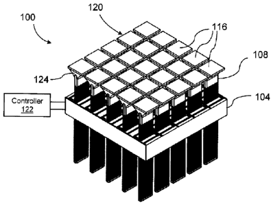
[0026] Reference is now made to Figures lA to 1F, which show various views of
an
exemplary polymorphic surface system denoted generally by reference 100. The
polymorphic
surface system comprises a guide structure 104 and a plurality of individual
surface contour
elements 108. A plurality of individual cavities 112 (see Figures 4A and 4B)
are formed in
the guide structure 104. As can be seen in the Figures, in a preferred
embodiment the cavities
112 extend entirely through the guide structure 104. Each surface contour
element 108 is
-11-
CA 02894983 2015-06-22
slidably received in a respective one of the individual cavities 112 for
reciprocal sliding linear
motion therein. In the exemplary embodiment, the superior surfaces 116 of the
surface
contour elements are generally square, and cooperate to form a polymorphic
surface 120. By
adjusting the linear position of the individual surface contour elements 108
within their
respective cavities 112, the polymorphic surface 120 can be made to assume a
variety of
shapes, as shown in Figures 1G and 1H. The polymorphic surface system includes
a
controller 122, shown schematically in Figures lA to 1F, which is adapted to
control the
mechanisms used to adjust the linear position of the individual surface
contour elements 108
within their respective cavities 112. The controller 122 may be, for example,
a suitably
programmed computer or microcontroller or other suitable device. Mechanisms
for adjusting
the linear position of the individual surface contour elements 108 within
their respective
cavities 112 will be described in greater detail below.
[0027] In the illustrated embodiment, each surface contour element 108 has a
head 124 that
defines the generally planar superior surface 116 and thus the heads 124 of
the surface
contour elements 108 cooperate to form the polymorphic surface 120. In other
embodiments,
the heads of the surface contour elements and the superior surfaces formed
thereby may have
other suitable shapes besides being generally planar. Moreover, as described
further below, in
other embodiments the surface contour elements may omit any head and instead
be movably
coupled to surface crowns, with the surface crowns forming the polymorphic
surface 120.
[0028] Reference is now made to Figures 2A to 2F, which show the exemplary
surface
contour elements 108 in more detail. Each of the surface contour elements 108
has at least
one electrically conductive path 132 thereon. In the illustrated embodiment,
the body portion
128 of each surface contour element 108, that is, the portion of the surface
contour element
108 that slides within the cavity 112 (not shown in Figures 2A to 2F), has a
series of
longitudinally spaced-apart conductive paths 132 extending along the length L
of the body
portion 128. In the exemplary embodiment, the conductive paths 132 take the
form of loops
extending around the body portion 128 transversely to the length L thereof
Also in the
exemplary embodiment, as shown in the cross-sectional views in Figures 2B and
2D, the body
portion 128 of each surface contour element 108 is preferably formed from a
magnetic or
-12-
CA 02894983 2015-06-22
magnetizable core 136 surrounded by an insulating protective layer 140, with
the conductive
paths 132 disposed outwardly of the insulating protective layer 140. It is not
necessary that
the body portion 128 of each surface contour element 108 comprise a magnetic
or
magnetizable core. In other embodiments, the core of the body portion of the
surface contour
element may be formed from a non-magnetizable material. The choice between
using a
magnetizable or magnetic material, or a non-magnetizable material, for the
core will depend
on the relative distance of the surface contour element from the source of the
magnetic field.
Where the gradient of the magnetic field at the surface contour element is
relatively small, the
core is preferably formed from a magnetic or magnetizable material, and where
the gradient
of the magnetic field at the surface contour element is relatively large, the
core is preferably
formed from a non-magnetizable material. Where the core 136 is non-conductive,
the
protective layer 140 need not possess insulating properties.
[0029] Reference is now made to Figures 3A to 3D, which show the
interrelationship between
the guide structure 104 and the surface contour elements 108 with reference to
a single
surface contour element 108 and a portion 104P of the guide structure 104
comprising a single
cavity 112 that slidingly receives the surface contour element 108.
[0030] Each of the cavities 112 has a magnetic field extending thereacross.
This magnetic
field is denoted schematically by the arrow M in Figures 3A and 3D; the
direction of the
arrow M shows the direction of the magnetic field. As can be seen in Figures
3A and 3D, in
the illustrated embodiment the magnetic field M across each cavity 112 is
substantially
perpendicular to the reciprocal sliding linear motion of the respective
surface contour element
108 within the respective cavity 112. The direction of the reciprocal sliding
linear motion of
the respective surface contour element 108 is shown by the two-headed arrow S;
the arrow S
is two-headed because the motion is reciprocal. In the illustrated embodiment,
a single
magnetic field M extends across all of the cavities 112; to achieve this, the
guide structure 104
comprises a magnetized ferromagnetic material to generate the single magnetic
field M. The
guide structure 104 is shown in isolation in Figures 4A and 4B, and in an
exemplary
embodiment may be formed by casting from a suitable ferromagnetic material.
The cavities
-13-
CA 02894983 2015-06-22
112 may be formed as part of the casting process, or after casting, for
example by drilling or
laser cutting.
[0031] In alternate embodiments, each cavity may have its own magnetic field,
and a plurality
of individual magnets may be arranged to provide each cavity with its own
magnetic field. In
such an embodiment, the individual magnets may be internal to the surface
contour elements
or the individual magnets may be electromagnets, in which case the controller
may be further
adapted to vary the magnetic fields generated by each individual
electromagnet. One example
of such an embodiment is described further below in the context of Figure 19.
[0032] Continuing to refer to Figures 3A to 3D, electrical contacts are
disposed in each cavity
112. The electrical contacts comprise a first side electrical contact 144 and
a second side
electrical contact 148. For each cavity 112, each first side electrical
contact 144 is electrically
isolated from each second side electrical contact 148 except for the
electrically conductive
paths 132 on the respective surface contour element 108 in the cavity 112. The
electrically
conductive paths 132 on the surface contour element 108 in the cavity 112
maintain electrical
communication between the first side electrical contact 144 and the second
side electrical
contact 148. The terms "side", "first side" and "second side", as used in this
context, are used
in the electrical rather than the physical sense and refer to the flow of
current across the
electrically conductive paths 132, which flow may be in either direction
between the first side
contact 144 and the second side contact 148 ¨ current flows from one contact
("side" of the
circuit) to the other. Thus, although the exemplary conductive paths 132 are
in the form of
loops, the current will not loop around the conductive paths 132 back to the
originating
contact but will travel across the conductive paths 132 to the contact on the
opposite "side".
Moreover, although in the exemplary embodiment the first side electrical
contacts 144 are
positioned directly opposite the second side electrical contacts 148 across
the respective
cavities 112, there is no requirement that the first and second side
electrical contacts have any
particular relative physical position so long as they are electrically
isolated from one another
except for the electrically conductive path(s) on the respective surface
contour element in the
cavity. The use of the term "side" in its electrical sense should not be read
as implying any
such physical requirement. As such, it will be appreciated that in alternate
embodiments,
-14-
CA 02894983 2015-06-22
there may be a plurality of first side contacts and/or a plurality of second
side electrical
contacts, with current flowing across the electrically conductive paths 132
between the first
side electrical contact(s) and the second side electrical contact(s).
[0033] Moreover, because the series of electrically conductive paths 132
extends along the
length L (Figure 2A) of the body portion 128, the electrically conductive
paths 132 will
maintain electrical communication between the first side electrical contact
144 and the second
side electrical contact 148 over a range of the reciprocal sliding linear
motion of the
respective surface contour element 108 within the respective cavity 112.
[0034] Accordingly, the first side electrical contact 144, the electrically
conductive paths 132
on the respective surface contour element 108 in the cavity 112 and the second
side electrical
contact 148 cooperate to form a circuit segment 152 of an electrical circuit
across the cavity
112. As can be seen in Figure 3D, in the illustrated embodiment the current
flowing through
the circuit segment 152, indicated by the arrow I, is substantially
perpendicular to the
magnetic field M across the cavity 112 and is also substantially perpendicular
to the
reciprocal sliding linear motion S of the respective surface contour element
108 within the
respective cavity 112. In Figure 3A the current I is perpendicular to the page
and in Figure
3B the magnetic field M is perpendicular to the page. When the current I flows
through the
circuit segment 152, the current I interacts with the magnetic field M across
the cavity 112 to
generate a Lorentz force that drives sliding linear motion S of the surface
contour element 108
within the cavity 112. The direction of the current I will determine the
direction of sliding
linear motion S of the surface contour element 108; the current I is therefore
denoted by a
two-headed arrow.
[0035] As seen in the detail view shown in Figure 3C, in a presently preferred
embodiment
the electrical contacts 144, 148 (only representative second side electrical
contact 148 is
shown in Figure 3C) comprise a base conducting layer 156 and a low friction
conducting
layer 160 that engages the conductive paths 132 to facilitate the sliding
linear motion S of the
surface contour element 108. The walls of the cavities 112 in the guide
structure 104 may
similarly be coated with a suitable low friction material.
-15-
CA 02894983 2015-06-22
[0036] As best seen in Figure 2E, each surface contour element 108 has a
respective length L,
width W and thickness T, with the length L being measured along the body
portion 128,
parallel to the reciprocal sliding linear motion S of the respective surface
contour element
108. As can be seen, the length L of each surface contour element 108 is
substantially greater
than its width W and the width W of each surface contour element is
substantially greater than
its thickness T, and the cavities 112 (not shown in Figure 2E) have a
corresponding shape.
The force applied to the surface contour element 108 is proportional to the
length of the
electrically conductive paths 132 between the first side electrical contact
144 and the second
side electrical contact 148 (not shown in Figure 2E), while the mass (and
effect of gravity) is
proportional to the volume of the surface contour element 108. Therefore, by
making the
thickness T of the surface contour element 108 smaller the same amount of
force can be
generated but with a smaller mass to be moved by that force. With reference
now specifically
to Figures 1C, 1D and 2B, it can be seen that in the illustrated embodiment,
the body portions
128 of the surface contour elements 108 are small enough to fit within the
cavities 112, while
the superior surfaces 116 of the heads 124 are wide enough to cover the
cavities 112. It is to
be appreciated that the body portions of the surface contour elements are not
limited to the
cross-sectional shape shown in Figure 2B, and may have any cross-sectional
shape that can be
received in a correspondingly shaped cavity for guided substantially linear
movement.
[0037] In an exemplary manufacturing process, one or more body portions for
surface contour
elements may be formed from a sheet of metal. On each side of the metal sheet,
an insulating
protective oxide layer is deposited on the metal, then a uniform layer of
conductive material is
deposited over the insulating protective oxide layer, and then a layer of
photoresist is
deposited over the conductive material. A pattern of strips extending
transversely to what will
become the length of the body portion is then cured, resulting in a series of
cured strips of
photoresist separated by uncured strips of photoresist in a striped pattern.
The uncured strips
of photoresist are then removed, exposing the conductive material underneath,
which is also
removed, leaving the oxide layer with strips of conductive material on top and
cured
photoresist over top of the strips of conductive material. The cured
photoresist is then
removed, leaving a sheet of metal having, on each side, an insulating
protective oxide layer
over top of which is disposed a series of spaced apart strips of conductive
material. The body
-16-
CA 02894983 2015-06-22
portions can then be cut from the metal sheet, for example by laser, and the
heads can then be
secured to the body portions, resulting in completed surface contour elements
in which the
metal forms the core, the insulating protective oxide forms the insulating
protective layer, and
the spaced apart strips of conductive material form the conductive paths. In
this embodiment,
the conductive paths will be opposed strips on either side of the body portion
rather than
loops, but this will not affect operation of the system as long as the
conductive paths engage
the first side electrical contact and the second side electrical contact and
the metal core is
electrically isolated from the first side electrical contact and the second
side electrical contact.
Alternatively, the edges of the cut body portions can be pinched (i.e.
flattened) to close the
strips into loops and electrically isolate the metal core, or a suitable
insulating coating may be
applied to the cut edges of the strips.
[0038] As noted above, the polymorphic surface system 100 includes a
controller 122 adapted
to control the mechanisms used to adjust the linear position of the individual
surface contour
elements 108 within their respective cavities 112. The controller 122 is part
of the electrical
circuit that includes the circuit segments 152 that control movement of the
respective surface
contour elements 108, and the controller 122 is adapted to address the circuit
segments 152 to
selectively apply current to, and remove current from, one or more selected
circuit segments
152. When the controller 122 applies a current I to a selected circuit segment
152, the applied
current I interacts with the magnetic field M across the respective cavity 112
to generate a
Lorentz force that drives sliding substantially linear motion S of the
respective surface
contour element 108 within the respective cavity 112. Each surface contour
element 108 can
be considered to be a resistor where the supplied current is proportional to
the acceleration of
the surface contour elements 108. The controller 122 can preferably
individually address
each circuit segment 152, and hence each surface contour element 108, so that
it can control
the position of each surface contour element 108 independently of the other
surface contour
elements 108. The controller 122 may control the current applied to each
circuit segment 152
by controlling the magnitude of the current and/or the duration of the
current. The electrical
circuit comprising the controller 122 and the circuit segments 152 that
control movement of
the respective surface contour elements 108 may be, for example, an active
matrix thin film
transistor circuit, which enables the controller 122 to control movement of
individual surface
-17-
CA 02894983 2015-06-22
contour elements 108. Such a circuit is within the capability of one skilled
in the art, now
informed by the herein disclosure.
[0039] As can be seen in the Figures, and particularly in Figures 1A, 1B, 4A
and 4B, in the
illustrated embodiment the cavities 112 and the surface contour elements 108
received therein
are arranged in a regular rectangular grid, with the surface contour elements
108 arranged to
move substantially in parallel with one another. The grid arrangement
facilitates the use of an
electrical circuit in which each circuit segment 152 (Figure 3D) is
individually addressable by
the controller 122, and conductive traces 164 (Figures 4A and 4B) extending
from the first
side electrical contact 144 and the second side electrical contact 148 may be
coupled to other
elements of the electrical circuit. For simplicity of illustration, Figures 4A
and 4B show the
conductive traces 164 as stubs and omit other features of the electrical
circuit.
[0040] It is not necessary that the cavities and surface contour elements be
arranged in a
rectangular grid, or that the surface contour elements be arranged to move
substantially in
parallel with one another. For example, the guide structure may take the form
of a segment of
a sphere, and the cavities and surface contour elements may be arranged for
reciprocal radial
movement of the surface contour elements toward and away from the center of
the sphere.
[0041] The exemplary polymorphic surface system 100 shown in Figures lA to 1H
has
twenty-five cavities 112 and twenty-five surface contour elements 108 arranged
in a 5 x 5
matrix for simplicity of illustration; it is to be understood that polymorphic
surface systems as
taught herein are not so limited. Increasing the physical area occupied by the
polymorphic
surface will increase the extent of the surface topography that can be
produced, and increasing
the number of surface contour elements per unit area increases the resolution.
In this sense,
the surface contour elements may be considered a three-dimensional analog to
pixels in a two-
dimensional display. As such, the number of surface contour elements per unit
area should be
made as large as practically possible up to the limits of the required
resolution in a given
application. Therefore, much larger matrices than the exemplary 5 x 5 matrix
are
contemplated.
-18-
CA 02894983 2015-06-22
[0042] While in a preferred embodiment the controller 122 can individually
address each
circuit segment 152 to individually control each surface contour element 108,
in other
embodiments the controller 122 may address groups of circuit segments 152 to
control groups
of surface contour elements 108. For example, in a polymorphic surface system
in which the
cavities and surface contour elements are arranged in a 100 x 100 matrix, the
controller may
address groups of circuit segments for which the corresponding cavities and
surface contour
elements form a 2 x 2 array. In such an arrangement, the heads of the surface
contour
elements may be linked to one another, or a group of surface contour elements
may share a
common head.
[0043] Reference is now made to Figures 5A to 5F and Figures 6A to 6C, which
show the
first exemplary polymorphic surface system 100 in combination with an
exemplary hydraulic
support system 500. The hydraulic support system 500 comprises a support block
504 having
a plurality of hydraulic support channels 512 defined therethrough. The
hydraulic support
channels 512 are in registration with the cavities 112 defined through the
guide structure 104,
and the support block 504 is preferably in sealing engagement with the guide
structure 104.
The hydraulic support channels 512 effectively extend the cavities 112, and
the lower part of
the body portion 128 of each surface contour element 108 is movably received
in a respective
hydraulic support channel 512. The lower end 170 of each surface contour
element 108, that
is, the end remote from the head 124, is fitted with a hydraulic plug 574 (see
Figure 6B)
which slidably sealingly engages the interior surface of the respective
hydraulic support
channel 512. Each hydraulic support channel 512 terminates, at the end remote
from the
guide structure 104, in an inverted frusto-conical valve aperture 576 (see
Figures 6A and 6C).
[0044] Referring in particular to Figures 6A and 6C, a valving block 578 is
movably
positioned at the end of the support block 504 that is remote from the guide
structure 104.
The valving block 578 is coupled to an actuator (not shown) for moving the
valving block 578
toward and away from the support block 504 to reduce and increase an
adjustable volume 586
(Figure 6C) between the valving block 578 and the support block 504. This
adjustable
volume 586 is sealed. For example, the support block 504 may be sealingly
fixed in a fluid-
tight housing (not shown) within which the valving block 578 is sealingly
slidingly received
-19-
CA 02894983 2015-06-22
so that the valving block 578 can slide toward and away from the support block
504 within
the housing. In such an embodiment, the adjustable volume 586 will be defined
by the face
588 (Figure 6C) of the support block 504, the face 590 (Figure 6C) of the
valving block 578
and the wall(s) of the housing within which the valving block 578 slides. The
valving block
578 carries a plurality of spaced apart conical valving members 580 arranged
in registration
with the frusto-conical valve apertures 576 on the support block 504. Each
valving member
580 cooperates with a respective valve aperture 576 to form a respective cone
valve 582. The
cone valves 582 are in fluid communication with a constant pressure reservoir
(not shown) via
the adjustable volume 586 and fluid transfer conduits 584 defined through the
valving block
578 and which communicate between the adjustable volume 586 and the constant
pressure
reservoir.
[0045] Moving the valving block 578 toward the support block 504 reduces the
adjustable
volume 586, forcing the fluid contained therein, which is under constant
pressure, to move
into the hydraulic support channels 512. When the valving block 578 engages
the support
block 504, the valving members 580 engage the valve apertures 576 to close the
cone valves
582, trapping fluid in the hydraulic support channels 512 to support the
surface contour
elements 108 even in the absence of an applied current. Moving the valving
block 578 away
from the support block 504 opens the cone valves 582, allowing fluid to escape
from the
hydraulic support channels 512 via the open cone valves 582 to the adjustable
volume 586 so
as to release the surface contour elements 108 to move freely. Thus, the
cavities 112, as
extended by the hydraulic support channels 512, are in valve-governed fluid
communication
with a fluid source for selectively (a) introducing fluid into the cavities
112/512 and sealing
the fluid within the cavities 112/512 to support the surface contour elements
108 in the
cavities 112/512 after discontinuing the applied current, and (b) withdrawing
the fluid from
the cavities 112/512 to release the surface contour elements 108.
[0046] In reference to the terms "support block" and "valving block", it is to
be understood
that the word "block" is not intended to imply that these components must be
of monolithic
construction, although monolithic construction is one preferred embodiment.
-20-
CA 02894983 2015-06-22
[0047] Optionally, polymorphic surface systems may be provided with a
secondary support
system, in addition to the hydraulic support system 500. One exemplary
implementation of
such a secondary support system will now be described with reference to
Figures 10A to 10C
and 11A to 11C, which show an exemplary surface contour element 108 in
association with
its respective portions 500P, 104P of the hydraulic support system 500 and the
guide structure
104. Figures 10A to 10C show the secondary support system in an unlocked
configuration
and Figures 11A to 11C show the secondary support system in a locked
configuration. For
simplicity of illustration, the base conducting layer, low friction conducting
layer and
electrical contacts of the portion 104P of the guide structure are not shown
in Figures 10A to
10C and 1 1 A to 11C.
[0048] The exemplary secondary support system shown in Figures 10A to 10C and
11A to
11C comprises a resilient elastomeric membrane 1002 interposed between the
support block
504 and the guide structure 104. The elastomeric membrane 1002 has a plurality
of locking
apertures 1004 (see Figures 10C and 11C) defined therethrough, with the
apertures 1004
arranged in registration with the respective surface contour elements 108,
cavities 112 and
hydraulic support channels 512. As such, the body portion 128 of the surface
contour
elements 108 extend through the locking apertures 1004. For ease of
illustration, Figures 10A
to 10C and 11A to 11C show only a portion of the elastomeric membrane 1002,
and only a
single locking aperture 1004, surface contour element 108, cavity 112 and
hydraulic support
channel 512.
[0049] The support block 504 and the guide structure 104 are relatively
movable toward and
away from one another, and a suitable actuator (not shown) may be provided to
effect such
movement. When the secondary support system is in the unlocked configuration,
as shown in
Figures 10A to 10C, the elastomeric membrane 1002 is relatively uncompressed
and the
interior surfaces 1006 of the locking apertures 1004 are spaced from the
surface contour
element 108 (see Figure 10C), permitting the surface contour element 108 to
move freely
along the cavity 112 and hydraulic support channel 512. When the support block
504 and the
guide structure 104 are moved toward one another, the elastomeric membrane
1002 is
compressed (relative to the condition shown in Figure 10C) and undergoes
elastomeric
-21-
CA 02894983 2015-06-22
deformation, causing the interior surfaces 1006 of the locking apertures 1004
to bulge
inwardly and engage the body portion 128 of the surface contour element 108
(see Figure
11C). This is the locked configuration (Figures 11A to 11C), in which the
deformed
elastomeric membrane 1002 grips the body portion 128 of the surface contour
element 108
and exerts frictional force thereon, thereby locking the surface contour
element 108 in place
as long as the elastomeric membrane 1002 is compressed. Moving the support
block 504 and
the guide structure 104 away from one another returns the secondary support
system to the
unlocked configuration, as shown in Figures 10A to 10C, allowing the
elastomeric membrane
1002 resile to its uncompressed shape and freeing the surface contour element
108 to move
along the cavity 112 and hydraulic support channel 512.
[0050] The exemplary secondary support system may be used to fix the surface
contour
elements 108 in place while the valving block 578 is moved toward the support
block 504 to
provide hydraulic support, and may also inhibit leakage.
[0051] The present disclosure also contemplates alternative structures for a
polymorphic
surface which rely on individual hydraulic control of the surface contour
elements rather than
electrical control thereof, and a hydraulic support structure similar to the
hydraulic support
structure 500 described above may be adapted to this purpose, for example by
using
individually controllable valves to govern fluid communication between an
adjustable volume
and the hydraulic support channels for the surface contour elements.
[0052] Polymorphic surface systems as described herein, and particularly
polymorphic
surface systems coupled to a hydraulic support system, may be adapted for use
in molding
operations. The controller may direct movement of the surface contour elements
so that the
polymorphic surface assumes a desired surface topography, and the polymorphic
surface can
then serve as all or part of a mold cavity. To facilitate this process and
inhibit leakage of the
material being molded between the surface contour elements, the polymorphic
surface may
further comprise a resilient surface layer, formed from a suitable resilient
and pliable material
impermeable to the material being molded, extending over the surface contour
elements. The
surface layer may be secured to the surface contour elements. Figure 13 shows
the exemplary
polymorphic surface system 100 with a resilient surface layer 1372 extending
over the surface
-22-
CA 02894983 2015-06-22
contour elements 108 and secured to the heads 124 thereof. When polymorphic
surface
systems as described herein are used in molding applications, the heads of the
surface contour
elements are preferably formed from an insulating material or are provided
with an insulating
layer or cap to limit heat transfer to the surface contour elements, in
particular the body
portions thereof, and thereby inhibit demagnetization and other damage.
[0053] Polymorphic surface systems as described herein can be further adapted
to molding
applications by providing "hollow" surface contour elements, that is, surface
contour elements
having respective lumens defined therethrough for the delivery of material
into the mold
cavity. In effect, the polymorphic surface system may be an array of surface
contour elements
configured to function as injection elements. It is not necessary for all of
the surface contour
elements to have lumens defined therethough; in some embodiments only a subset
of the
surface contour elements may have lumens.
[0054] Reference is now made to Figures 12A though 12C, which show the
arrangement of a
second exemplary surface contour element 12108 in association with its
respective portions
12500P, 104P of a second exemplary hydraulic support system 12500 and a guide
structure
104. The guide structure 104 shown in Figures 12A though 12C is identical to
the guide
structure 104 described above and hence is denoted by the same reference
numeral.
[0055] The second exemplary surface contour element 12108 shown in Figures 12A
through
12C is similar to the first exemplary surface contour element 108 described
above, with like
reference numerals used to denote like features except with the additional
prefix "12". The
second exemplary surface contour element 12108 shown in Figures 12A though 12C
differs
from the first exemplary surface contour element 108 in that it is adapted to
function as an
injection element. A cylindrical lumen 1202 (Figure 12B) extends
longitudinally through the
surface contour element 12108, and the surface contour element 12108 does not
include a
hydraulic plug, or includes an annular hydraulic plug, leaving the lumen 1202
unobstructed.
In other embodiments, the lumen may have other suitable shapes besides
cylindrical.
[0056] The second exemplary hydraulic support system 12500 is also similar to
the first
exemplary hydraulic support system 500, with like reference numerals denoting
like features
-23-
CA 02894983 2015-06-22
but with the additional prefix "12". The second exemplary hydraulic support
system 12500
differs from the first exemplary hydraulic support system 500 in that it has
been modified to
accommodate an injection system.
[0057] A needle-like injector 1204 (Figure 12B) extends from each of the
conical valving
members 12580 of the second exemplary hydraulic support system 12500. The
injector 1204
is arranged coaxially with the conical valving member 12580 and extends
superiorly thereof
through the respective valve aperture 12576 and hydraulic support channel
12512 into the
lumen 1202 of the surface contour element 12108. The injector 1204 is sized
and shaped to
be sealingly slidingly received within the lumen 1202 of the surface contour
element 12108,
and is therefore necessarily smaller in diameter than the hydraulic support
channel 12512.
Accordingly, there is an annular gap 1206 (Figure 12B) between the outer
surface of the
injector 1204 and the inner surface of the hydraulic support channel 12512,
and part of the
body portion of the surface contour element 12108 is slidingly sealingly
received in the
annular gap 1206. The annular gap 1206 is in fluid communication with the
adjustable
volume 12586, such that moving the valving block 12578 toward the support
block 12504
reduces the adjustable volume 12586, forcing the fluid contained therein to
move into the
annular gap 1206. When the valving block 12578 engages the support block 12504
as shown
in Figures 12A to 12C, the valving members 12580 engage the valve apertures
12576 to close
the cone valves 12582, trapping fluid in the annular gap 1206 to support the
surface contour
elements 12108. When the valving block 12578 moves away from the support block
12504,
the cone valves 12582 open to allow fluid to escape from the annular gap 1206
and release the
surface contour elements 12108 to move freely.
[0058] The injector 1204 has an injection lumen 1208 (Figure 12B) extending
longitudinally
therethrough. The injection lumen 1208 also extends inferiorly through the
conical valving
member 12580 into the valving block 12578, and the injection lumen 1208 is in
fluid
communication with a fluidic piping network 1210 formed in the valving block
12578. As
such, various fluids can be pumped through the valving block 12578, the
conical valving
member 12580 and the injection lumen 1208 into the lumen 1202 of the surface
contour
element 12108 and through a fluid aperture 1212 in the head 12124 of the
surface contour
-24 -
CA 02894983 2015-06-22
element 12108. It should be noted that the fluidic piping network 1210, the
injection lumen
1208 and the lumen 1202 of the surface contour element 12108 are not in fluid
communication with the adjustable volume 12586 and are not in fluid
communication with
the annular gap 1206 between the injector 1204 and the hydraulic support
channel 12512.
Thus, although in the illustrated embodiment the fluidic piping network 1210
extends through
the valving block 12578 and the injection lumen 1208 extends through the
conical valving
member 12580 into the valving block 12578, the injection system is
functionally separate and
distinct from the hydraulic support system 12500.
[0059] For ease of illustration, only a single exemplary injection-capable
surface contour
element 12108 is shown, together with the associated portions 12500P, 104P of
the second
exemplary hydraulic support system 12500 (accommodating the injection system)
and the
guide structure 104. As will be readily understood in view of the foregoing
description, a
plurality of injection-capable surface contour elements 12108 assembled in
combination with
a complete hydraulic support system 12500 and guide structure 104 will form an
injection-
capable polymorphic surface system.
[0060] In one embodiment, two opposed injection-capable polymorphic surface
systems
could be configured to form the halves of a mold having a mold cavity of the
desired shape, or
a single injection-capable polymorphic surface system could be arranged in
opposition to a
static mold half or plate, with the injection-capable surface contour elements
being coupled in
fluid communication, via the fluidic piping network, with a source of liquid
material to be
molded. With the mold formed by the opposed polymorphic surfaces closed, the
material
could then be injected into the mold cavity through the lumens in the
injection-capable
surface contour elements to fill the mold cavity. This type of arrangement is
not limited to a
single injection-capable polymorphic surface system or two injection-capable
polymorphic
systems forming opposed mold halves; polymorphic surface systems may be
arranged to form
faces of a polyhedral mold. Thus, one method for molding an object comprises
configuring at
least one polymorphic surface system to form at least part of a mold cavity,
and injecting
material into the mold cavity through lumens defined through at least some of
the surface
contour elements of the polymorphic surface system(s). It is also contemplated
that mold
-25-
CA 02894983 2015-06-22
arrangements may combine one or more injection-capable polymorphic surface
systems with
one or more polymorphic surface systems that are not injection-capable.
[0061] In a similar embodiment, different injection-capable surface contour
elements may be
coupled, via the fluidic piping network, in fluid communication with different
material
sources so as to be able to deliver different materials into the mold cavity
formed by the
polymorphic surface system(s). Thus, a first group of injection-capable
surface contour
elements is coupled in fluid communication with at least one source of a first
material, and a
second group of injection-capable surface contour elements is coupled in fluid
communication
with at least one source of a second material, with the second material being
different from
the first material. This arrangement permits the molding of multilayer
objects. For example,
a first mold cavity having a first shape may be formed by the polymorphic
surface system(s)
and the first material injected into the first mold cavity and allowed to
solidify (optionally
with active cooling). A second mold cavity having a second shape may then be
formed by the
polymorphic surface system(s) and the second material injected into the second
mold cavity.
The intermediate object formed from the first material may be maintained in
the desired
position and orientation, both during transition of the polymorphic surface
system(s) between
the first configuration forming the first mold cavity and the second
configuration forming the
second mold cavity and during injection of the second material into the second
mold cavity,
by a subset of the surface contour elements. The subset of the surface contour
elements can
be withdrawn once the second material has solidified sufficiently to maintain
the desired
orientation of the intermediate object within the second mold cavity while
still being
sufficiently non-viscous to fill the gaps formed by withdrawal of the subset
of the surface
contour elements. Optionally, the subset of the surface contour elements may
be injection-
capable surface contour elements, and can deliver the second material into the
gap as they
withdraw. The arrangements and methods described above are not limited to two
materials
and two sequential mold cavities, and can be extended, mutatis mutandis, to
three, four or
more materials and three, four or more sequential mold cavities. It is also to
be appreciated
that an individual layer need not completely encapsulate an intermediate
object formed by the
previous step, and as such a layer may cover only a portion of the surface of
the object formed
by the preceding layer. For example, a metal reinforcement may be injected
into a portion of
-26-
CA 02894983 2015-06-22
a plastic component between plastic layers, or onto a surface of a plastic
component. It is also
contemplated that a fluid not intended to form part of the finished article
may be injected
using injection-capable surface contour elements. For example, air or an inert
gas may be
injected against a portion of the surface of a still-molten article to subject
that portion of the
surface to differential stresses so as to strengthen that portion of the
surface or impart surface
features thereto. Furthermore, in some embodiments a vacuum may be applied via
injection-
capable surface contour elements, so that a suitable cooling fluid may be
applied via a first set
of injection-capable surface contour elements and withdrawn via a second set
of injection-
capable surface contour elements. Application of a vacuum to an injection-
capable surface
contour element may be seen conceptually as a negative injection.
[0062] Polymorphic surface systems having hollow or injection-capable surface
contour
elements can be used in further applications besides molding. One such
application is
printing, in which a polymorphic surface element may be configured into a
desired print
surface, which may be continuously inked by supplying ink through the lumens
of the hollow
surface contour elements so as to maintain a continuously inked surface. The
use of a
polymorphic surface system can provide a dynamically changeable print surface,
which can
be used in offset printing or direct printing. Other applications for
polymorphic surface
systems having hollow surface contour elements include vacuforming, where a
vacuum can
be applied via the lumens, steam forming of wood, and lubricant application.
[0063] Another application for injection-capable polymorphic surface systems
is 3D printing.
A first group of injection-capable surface contour elements may be coupled in
fluid
communication with at least one source of a first material, a second group of
injection-capable
surface contour elements may be coupled in fluid communication with at least
one source of a
second material, and so on, to enable simultaneous 3D printing using two or
more materials.
[0064] Additionally, by applying a vacuum to one or more injection-capable
surface contour
elements, the injection-capable surface contour element(s) may be used to draw
fluid from
one or more sample sources, for example in a robotic armature used in
biological sampling.
In such embodiments, one or more of the injection-capable surface contour
elements may be
provided with a suitable sharpened, needle-shaped head.
-27-
CA 02894983 2015-06-22
[0065] In addition, polymorphic surface systems as described herein may be
applied to rapid
prototyping. By having the controller direct movement of the surface contour
elements so
that the polymorphic surface assumes a desired surface topography, a transient
model of a
desired product, or a portion thereof, can be rapidly generated for initial
testing. For example,
when the polymorphic surface has sufficient resolution and comprises a
resilient surface layer,
the polymorphic surface can be made to conform to a proposed automotive body
shape for
initial wind tunnel testing. Temporary models generated by polymorphic surface
systems as
described herein may also be used to test inter-fit of various parts.
[0066] In a preferred embodiment, the controller 122 is further adapted to
detect the linear
position of each surface contour element 108 relative to its respective cavity
112, and sensors
coupled to the controller 122 may be incorporated into or otherwise associated
with the guide
structure 104 to achieve this end. Such sensors may measure the current
generated through an
inductor as a result of a gradient magnetic field moving past the sensor's
position (i.e. the
body portion 128 of each surface contour element 108 will create a current).
[0067] Reference is now made to Figure 7, which shows the positioning of an
exemplary
solenoid sensor 792 relative to a respective surface contour element 108. The
solenoid sensor
792 comprises a helix of wire that may be embedded in the guide structure 104
(not shown in
Figure 7) surrounding and extending longitudinally along a respective cavity
112 (also not
shown in Figure 7) so that the helix will loosely surround the body portion
128 of the surface
contour element 108. As the body portion 128 of the surface contour element
108 moves
within the cavity 112 a positive or negative current, depending on the
direction of movement,
will be generated in the solenoid sensor 792, with the amount of current
generated being
proportional to the rate of motion of the surface contour element 108. The
generated current
can be detected and analyzed by the controller 122 to determine the linear
position of the
surface contour element 108 relative to the cavity 112.
[0068] Instead of solenoid sensors, a passive matrix arrangement may be
coupled to the
controller 122 and used to enable the controller 122 to detect the linear
position of each
surface contour element 108 relative to its respective cavity 112. Figure 8
shows the
positioning of an exemplary passive matrix sensor 794 relative to a respective
surface contour
-28 -
CA 02894983 2015-06-22
element 108. The passive matrix sensor 794 comprises a layered mesh of
conductive trace
layers 796 embedded in the guide structure 104 (not shown in Figure 8)
surrounding and
extending longitudinally along the cavities 112 (also not shown in Figure 8)
so that the series
of conductive trace layers 796 will loosely surround the body portion 128 of
each surface
contour element 108. Similarly to the solenoid sensor 792 (Figure 7), movement
of the body
portion 128 of the surface contour element 108 within the cavity 112 will
induce a current
into certain ones of the conductive trace layers 796, which current can be
detected by the
controller 122 (not shown in Figure 8). However, instead of detecting movement
of each
surface contour element 108 separately as with the solenoid sensors 792, the
passive matrix
arrangement will detect movement of all of the surface contour elements 108
simultaneously
by measuring the current at the beginning and end of each conductive trace
layer 796. The
controller 122 can implement a matrix solver algorithm to mathematically
determine the
speed and position of each surface contour element 108.
[0069] In other embodiments, the linear position of each surface contour
element 108 relative
to its respective cavity 112 may be detected by the use of laser or acoustic
ranging to detect
reflections from the inferior end of the surface contour elements 108 (i.e.
the ends opposite
the heads 124).
[0070] Where a polymorphic surface system as described herein includes
sensors, such as the
solenoid sensors 792 or the passive matrix sensor 794, for detecting movement
of the surface
contour elements, the controller may be further adapted to detect resistance
to sliding linear
motion of individual surface contour elements by comparing an expected rate of
sliding linear
motion to an actual rate of sliding linear motion. This permits a polymorphic
surface system
as described herein to be used as a measuring device to measure the surface
topography of an
object. The controller can cause the surface contour elements to be retracted
(i.e. positioned
so that the heads thereof are as close as possible to the guide structure),
and the object to be
measured can then be placed on the polymorphic surface formed by the retracted
surface
contour elements. The controller can then cause the surface contour elements
to extend (i.e.
move the heads thereof away from the guide structure). When a surface contour
element
engages the surface of the object to be measured, its rate of movement will
decrease because
-29-
CA 02894983 2015-06-22
of the physical resistance of the object, and this detected decrease in the
rate of movement can
be detected by the controller as indicating the presence of the object such
that the topography
of the object can be mapped.
[0071] It is also contemplated that, in an embodiment where the cores 136 (see
Figures 2B
and 2D) of the surface contour elements 108 are magnetic or magnetized, the
controller 122
may be adapted to function in a passive measurement mode to detect current
induced across
each circuit segment 152 by movement of the respective surface contour element
108 under
external force. In such an embodiment, the polymorphic surface system may be
used to
measure the surface topography of an object. For example, in the arrangement
shown in
Figures 5A to 5F and Figures 6A to 6C, the hydraulic support system 500 may be
used to
support the surface contour elements 108 so that the polymorphic surface 120
is generally
planar as shown. An object to be measured could then be placed on the
polymorphic surface
120, and the mass of the object would cause some of the surface contour
elements 108 to be
displaced toward the valving block 578 as the polymorphic surface 120 assumes
the shape of
the object being measured. The surface contour elements 108 would be displaced
by different
distances according to the shape of the measured object, resulting in
different currents being
induced across each circuit segment 152 (Figure 3D). These currents could then
be detected
by the controller 122 and used to develop a three-dimensional model of the
portion of the
object surface that engaged the polymorphic surface 120.
[0072] In addition to measuring surface topography of an object, it is also
contemplated that
polymorphic surface systems may be adapted for testing mechanical properties
of an object's
surface. To achieve this, the surface contour elements 108 could be driven
against the surface
of the object and the effect of the impact could be measured by relating the
force exerted by
the surface contour element 108 and its displacement (position) as given by
the sensing
element. In one implementation, the surface contour elements 108 could be
placed in contact
with the object being tested and a constant force applied while the
displacement is measured
or, conversely, a constant rate of displacement could be achieved while
measuring the applied
force. The force produced by a given surface contour element 108 will be a
function of the
current flowing through the conductive path(s) 132 of that surface contour
element 108, and
-30-
CA 02894983 2015-06-22
the position of each surface contour element 108 can be determined by a
suitable sensor
arrangement, such as the sensor arrangements described above. In addition,
measurements of
surface properties may also be obtained by driving surface contour elements
108 against the
surface of the object being measured to generate impacts therebetween. By
oscillating or
pulsing the surface contour elements 108 into and out of contact with the
surface being
measured and varying the frequency, or by varying the velocity at which the
surface contour
elements 108 impact the object surface, non-Newtonian properties of the
surface (which
depend on shear rate) could also be determined.
[0073] Reference is now made to Figures 14A to 140, which illustrate a third
exemplary
embodiment of a polymorphic surface system, denoted generally by reference
numeral 14100.
The third exemplary polymorphic surface system 14100 shown in Figures 14A to
140
functions in the same way as the first polymorphic surface system 100, that
is, by way of
current interacting with a magnetic field to generate a Lorentz force that
drives guided
substantially linear motion of the surface contour elements 14108. As such,
corresponding
reference numerals denote corresponding features, except with the additional
prefix "14".
Moreover, the surface contour elements 14108 of the third polymorphic surface
system 14100
are "headless" and are pivotally coupled to hexagonal surface crowns 1424
which cooperate
to form the polymorphic surface 14120 as shown in Figures 14L to 140. A
portion of the
third exemplary polymorphic surface system 14100 including three surface
contour elements
14108 and a portion 14104P of the guide structure 14104 is shown in Figures
14A to 14F,
Figures 14G to 141 show an exemplary surface contour element 14108, Figures
14J to 14L
show a surface crown 1424 and Figures 14M to 140 show the complete polymorphic
surface
system 14100.
[0074] As can be seen in Figures 14A to 14D and 14F, three surface contour
elements 14108
are coupled to each surface crown 1424, and each surface contour element 14108
is coupled
to only a single surface crown 1424. Because each surface contour element
14108 is coupled
to only a single surface crown 1424, the position and orientation of each
surface crown 1424
can be set independently of the position and orientation of each other surface
crown 1424,
-31-
CA 02894983 2015-06-22
although the footprint of each surface crown 1424 covers three surface contour
elements
14108.
[0075] The surface contour elements 14108 are similar to the surface contour
elements 108 in
the first embodiment except that instead of a head 124, each surface contour
element 14108
has a cornute superior end 1426 which terminates in a ball 1428. The surface
crowns 1424
each have a regular hexagonal shape and a generally planar superior surface
1416, and have
three radially arranged penannular channels 1442 on the inferior surface 1446
thereof; the
penannular channels 1442 are arranged at 120 degree intervals. Each of the
balls 1428 is
slidingly received in a respective one of the penannular channels 1442 so as
to be able to slide
along the penannular channel 1442 and also pivot within the penannular channel
1442. Thus,
the cornute superior end 1426 and ball 1428 combination of each surface
contour element
14108 forms a ball stud and cooperates with the respective penannular channel
1442 to form a
sliding ball joint.
[0076] The vertical position of each surface crown 1424 is determined by the
average vertical
position of the three surface contour elements 14108 to which that surface
crown 1424 is
coupled and the angular orientation of the surface crown 1424 is determined by
the relative
differences among the vertical positions of the three surface contour elements
14108 to which
that surface crown 1424 is coupled. As an alternative to coupling the surface
contour
elements 14108 to the surface crowns 1424 by having the surface contour
elements 14108
slide within channels 1442 formed in the surface crowns 1424, the surface
contour elements
may be coupled to the surface crowns by way of an elastic deformable membrane.
[0077] Reference is now made to Figures 15A to 15J, which show a fourth
exemplary
polymorphic surface system, indicated generally by the reference 15100. The
fourth
exemplary polymorphic surface system 15100 is similar in overall structure to
the first
polymorphic surface system 100, and as such corresponding reference numerals
denote
corresponding features, except with the additional prefix "15". Like the first
polymorphic
surface system 100, the fourth exemplary polymorphic surface system 15100
functions by
way of current interacting with a magnetic field to generate a Lorentz force
that drives guided
substantially linear motion of the surface contour elements 15108. However,
the structure of
-32 -
CA 02894983 2015-06-22
the fourth exemplary polymorphic surface system 15100 used to generate the
Lorentz force
differs from the corresponding structure of the first polymorphic surface
system 100, as will
be explained further below. Figures 15A to 15F show the complete polymorphic
surface
system 15100, and a more detailed view of a portion of the fourth exemplary
polymorphic
surface system 15100 including a single surface contour element 15108 and a
portion 15104P
of the guide structure 15104 is shown in Figures 15G to 15J.
[0078] The fourth exemplary polymorphic surface system 15100 comprises a guide
structure 15104 and plurality of surface contour elements 15108. The guide
structure 15104
has a plurality of individual cavities 15112 formed therein, and each surface
contour element
15108 is slidably received in a respective one of the individual cavities
15112 for guided
reciprocal substantially linear motion, denoted in the drawings by arrow "S",
within the
respective cavity 15112. Each of the surface contour elements 15108 generates
a respective
magnetic field, the direction of which is indicated in the drawings by the
arrow "M". For
example, the surface contour elements 15108 may be formed from, or contain, a
suitable
magnetized ferromagnetic material to generate the magnetic field M. Respective
circuit
segments 15152 of an electrical circuit extend across each cavity 15112; in
the illustrated
embodiment each circuit segment comprises a first side electrical contact
15144, a second
side electrical contact 15148, and at least one electrically conductive bridge
15132 extending
across the cavity 15112 and connecting the first side electrical contact 15144
and the second
side electrical contact 15148 in electrical communication with one another.
Accordingly, the
first side electrical contact 15144, the electrically conductive bridge 15132
in the cavity
15112 and the second side electrical contact 15148 cooperate to form the
circuit segment
15152. The electrical circuit further includes a controller 15122 adapted to
individually
address the circuit segments to selectively apply current to, and remove
current from, one or
more selected circuit segments 15152.
[0079] As can be seen in Figure 15J, in the illustrated embodiment the current
flowing
through the circuit segment 15152, indicated by the arrow I, is substantially
perpendicular to
the magnetic field M across the cavity 15112 and is also substantially
perpendicular to the
reciprocal sliding linear motion S of the respective surface contour element
15108 within the
-33 -
CA 02894983 2015-06-22
respective cavity 15112. In Figure 15G the magnetic field M is perpendicular
to the page, and
in Figure 15H the current I is perpendicular to the page. Upon application of
current to a
selected one of the circuit segments 15152, the applied current I flows
through the circuit
segment 15152 and interacts with the respective magnetic field M across the
respective cavity
15112 to generate a Lorentz force that drives guided substantially linear
motion S of the
surface contour element 15108 within the cavity 15112. The direction of the
current I will
determine the direction of sliding linear motion S of the surface contour
element 15108; the
current I is therefore denoted by a two-headed arrow.
[0080] As seen in the detail view shown in Figure 151, in a presently
preferred embodiment
each surface contour element 15108 comprises a magnetized ferromagnetic core
15136
surrounded by an insulating protective layer 15140, preferably of a low
friction material. The
walls of the cavities 15112 in the guide structure 15104 may similarly be
coated with a
suitable low friction material.
[0081] The structure of the fourth exemplary polymorphic surface system 15100
can be
modified and integrated with other structures or arrangements described
herein, for example
(and without limitation) by being combined with a hydraulic support system
and/or secondary
support system, or by using surface crowns, or by adding injection capability,
or a resilient
surface layer.
[0082] An aggregated polymorphic surface arrangement, comprising a plurality
of individual
polymorphic surface systems of the type shown and described above, is also
contemplated. In
an aggregated polymorphic surface arrangement, each polymorphic surface system
is carried
and supported by a respective individual linear actuator so that the entire
polymorphic surface
system can be moved substantially linearly by the linear actuator,
independently of any
movement of the individual surface contour elements and independently of the
other
polymorphic surface systems in the aggregated polymorphic surface arrangement.
In a
preferred embodiment, the polymorphic surface systems and their respective
individual linear
actuators are arranged so that substantially linear movement of the
polymorphic surface
system, as driven by the respective linear actuator, is parallel to the
substantially linear
movement of the surface contour elements. The linear actuators may be Lorentz
force
-34 -
CA 02894983 2015-06-22
actuators constructed according to the principles described herein, or may be
conventional
linear actuators such as solenoid actuators or motorized gear-driven
actuators. Figures 16A to
16C show an assembly 1600 comprising the first exemplary polymorphic surface
system 100
in combination with the exemplary hydraulic support system 500, with the
assembly 1600
being carried by a linear actuator 1602.
[0083] The linear actuators, and hence the polymorphic surface systems 100
carried thereby,
may be configured in an array. Thus, an aggregated polymorphic surface
arrangement may be
an array of individually linearly movable polymorphic surface systems 100,
with linear
movement of the polymorphic surface systems 100 being in parallel with one
another and in
parallel with the linear movement of the surface contour elements 108.
[0084] The use of an aggregated polymorphic surface arrangement can provide an
enhanced
topographical range as compared to an individual polymorphic surface system
100. The
topographical range of a single polymorphic surface system 100 will be limited
by the range
of movement of the individual surface contour elements 108, and will not be
able to
accurately model a surface whose topographical variations exceed this range.
The use of an
aggregated polymorphic surface arrangement obviates this limitation, since the
linear
actuators can be used for larger or "gross" topographical position adjustments
while the
surface contour elements 108 are used for smaller or "fine" topographical
position
adjustments.
[0085] In certain embodiments, polymorphic surface systems as described
herein, as well as
aggregated polymorphic surface arrangements, may be enhanced by applying
color. In the
simplest such embodiment, a suitable projector may be arranged to project an
image onto the
heads 124 of the surface contour elements 108, in a manner similar to that
described in
Folmer et al., "inFORM: Dynamic Physical Affordances and Constraints through
Shape and
Object Actuation" (Paper delivered at UIST'13, The 26th Annual ACM Symposium
on User
Interface Software and Technology, 8-11 October 2013), (2014) CHI '14.
[0086] In another embodiment, the surface contour elements may be formed from
a suitable
transparent material, such as a suitable glass or plastic, and configured to
achieve substantially
-35-
CA 02894983 2015-06-22
total internal reflection, other than for light reaching the head of the
surface contour element,
so that each surface contour element can function as a light conduit,
similarly to a fiber optic
cable. An array of light emitting devices, such as light emitting diodes or
lasers, can be
positioned to deliver light to the surface contour elements. For example, an
array of light
emitting devices could be placed below the guide structure of a polymorphic
surface system.
The transparent surface contour elements would then carry the delivered light
to the heads of
the surface contour elements so as to generate an image on the heads of the
surface contour
elements. The desired refractive index for the surface contour elements may be
achieved
through material selection, or by coating the edges of the surface contour
elements with a
suitable reflective cladding layer. In the latter case, the conductive layer
will be disposed
outside of the cladding layer along with a thin, highly magnetically
susceptible layer. Figure
17 shows portions 17104P, 17500P of a fifth exemplary polymorphic surface
system and
associated hydraulic support system respectively. The polymorphic surface
system 17100 and
hydraulic support system 17500 are similar to the first exemplary polymorphic
surface system
100 and hydraulic support system 500, with like references denoting like
features except with
the prefix "17". The fifth exemplary polymorphic surface system 17100 and
associated
hydraulic support system 17500 differ from the first exemplary polymorphic
surface system
100 and hydraulic support system 500 in that the former are adapted to
transmit light through
the surface contour elements 17108 to the superior surfaces 17116 thereof. A
light source,
shown schematically as a block 1700, is coupled to an optical fiber 1702
extending through a
bore 1704 in the valving block 17578 to transmit light through the hydraulic
support channel
17512 to the inferior end of the surface contour element 17108. The interior
surface of the
hydraulic support channel 17512 may be coated with a reflective material to
facilitate light
transmission therealong, and the hydraulic fluid used is selected to have a
suitable refractive
index. The surface contour element 17108 comprises a transparent material that
achieves
sufficient, and preferably substantially total, internal reflection so that
light received at the
inferior end of the surface contour element 17108 is transmitted to the
superior surface 17116
thereof so as to be visible thereon. Thus, the superior surface 17116 of each
surface contour
element 17108 functions as a pixel, and by transmitting different colors of
light to each
surface contour element, an image can be presented on the polymorphic surface
formed
-36-
CA 02894983 2015-06-22
thereby. Since the superior surface 17116 of each surface contour element
17108 has an X, Y
and Z position as well as a color, the superior surface 17116 may be
considered a voxel and
used to create a three-dimensional image with coloring on its superior
surface. For example,
the fifth exemplary polymorphic surface system may be used to present a
colored
topographical map. Other embodiments of a polymorphic surface system which are
not
associated with a hydraulic support system may also be adapted to transmit
light through the
surface contour elements to the superior surfaces thereof.
[0087] The controller (e.g. controller 122, 15122) for a polymorphic surface
system may be,
for example, a suitably programmed computer or microcontroller or other
suitable device, or a
combination of a suitably programmed computer with a microcontroller or other
suitable
device. For example, a polymorphic surface system may include a
microcontroller that is
communicatively coupled to a programmed computer. As such, polymorphic surface
systems
as described herein may be responsive to computer-generated instructions to
generate
topographical shapes representing three-dimensional information stored in or
generated by a
computer system. The computer system may fulfill the role of the controller,
or may
communicate with the controller.
[0088] An illustrative computer system in association with which the
polymorphic surface
systems herein described may be implemented is presented as a block diagram in
Figure 9.
The illustrative computer system is denoted generally by reference numeral 900
and includes
a display 902, input devices in the form of keyboard 904A and pointing device
904B,
computer 906 and external devices 908 coupled to the computer 906. One of the
external
devices 908 coupled to the computer 906 includes, as a combination, a
polymorphic surface
system 100 and hydraulic support system 500 as described above. While pointing
device
904B is depicted as a mouse, it will be appreciated that other types of
pointing device may
also be used. In one embodiment, a polymorphic surface system as described
herein may be
used as an input device. For example, in some embodiments a polymorphic
surface may
function as a dynamically adaptive keyboard and/or pointing device. More than
one
polymorphic surface system may be coupled to a single computer system.
-37-
CA 02894983 2015-06-22
[0089] The computer 906 may contain one or more processors or microprocessors,
such as a
central processing unit (CPU) 910. The CPU 910 performs arithmetic
calculations and control
functions to execute software stored in an internal memory 912, preferably
random access
memory (RAM) and/or read only memory (ROM), and possibly additional memory
914. The
additional memory 914 may include, for example, mass memory storage, hard disk
drives,
optical disk drives (including CD and DVD drives), magnetic disk drives,
magnetic tape
drives (including LTO, DLT, DAT and DCC), flash drives, program cartridges and
cartridge
interfaces such as those found in video game devices, removable memory chips
such as
EPROM or PROM, emerging storage media, such as holographic storage, or similar
storage
media as known in the art. This additional memory 914 may be physically
internal to the
computer 906, or external as shown in Figure 9, or both.
[0090] The computer system 900 may also include other similar means for
allowing computer
programs or other instructions to be loaded. Such means can include, for
example, a
communications interface 916 which allows software and data to be transferred
between the
computer system 900 and external systems and networks. Examples of
communications
interface 916 can include a modem, a network interface such as an Ethernet
card, a wireless
communication interface, or a serial or parallel communications port. Software
and data
transferred via communications interface 916 are in the form of signals which
can be
electronic, acoustic, electromagnetic, optical or other signals capable of
being received by
communications interface 916. Multiple interfaces, of course, can be provided
on a single
computer system 900. In one embodiment, it is contemplated that input received
at a first
polymorphic surface device coupled to a first computer system may be
transmitted to a
second computer system via a suitable network and presented by a second
polymorphic
surface device coupled to a second computer system. Such communication may be
bi-
directional, and may be used, for example, to facilitate telemedicine.
[0091] Input and output to and from the computer 906 is administered by the
input/output
(I/0) interface 918. This I/0 interface 918 administers control of the display
902, keyboard
904A, external devices 908, including the combined polymorphic surface system
100 and
hydraulic support system 500, and other such components of the computer system
900. The
-38-
CA 02894983 2015-06-22
computer 906 also includes a graphical processing unit (GPU) 920. The latter
may also be
used for computational purposes as an adjunct to, or instead of, the (CPU)
910, for
mathematical calculations.
[0092] The various components of the computer system 900 are coupled to one
another either
directly or by coupling to suitable buses.
[0093] The term "computer system", as used herein, is not limited to any
particular type of
computer system and encompasses servers, desktop computers, laptop computers,
networked
mobile wireless telecommunication computing devices such as smartphones,
tablet
computers, as well as other types of computer systems.
[0094] The apparatus described herein represent exemplary, and non-limiting,
implementations of a method for dynamically forming a surface topography. This
method
comprises applying at least one magnetic field across a plurality of movable
surface contour
elements and selectively passing a current through the magnetic field(s)
adjacent selected
surface contour elements, with the current being substantially perpendicular
to the magnetic
field(s). The result is that for each selected surface contour element, the
current interacts with
the magnetic field to generate a Lorentz force that drives guided
substantially linear motion of
the respective surface contour element. In certain preferred embodiments, the
guided
substantially linear motion of the respective selected surface contour element
is substantially
perpendicular to both the magnetic field(s) and to the current across the
selected surface
contour elements. Preferably, the surface contour elements are individually
moveable and
individually selectable for application of current to generate movement. The
method may
further comprise supporting the surface contour elements in position after
removing the
current. The method may further comprise controlling the current applied
across each
selected surface contour element to control the amount of guided substantially
linear motion
of the selected surface contour element.
[0095] In some embodiments of the method, for example in an implementation of
the method
using the first exemplary polymorphic surface system 100, there may be a
single magnetic
field. In the first exemplary polymorphic surface system 100, selectively
passing a current
-39 -
CA 02894983 2015-06-22
through the magnetic field adjacent the selected individual surface contour
elements is
achieved by selectively applying the current across the selected individual
surface contour
elements by way of the respective electrically conductive paths 132 on the
respective surface
contour elements 108. Thus, Figures 1A to 4B illustrate one implementation of
the above-
described method.
[0096] In other embodiments of the method, for example in an implementation of
the method
using the fourth exemplary polymorphic surface system 15100, there may be a
plurality of
individual magnetic fields, with each individual magnetic field being
generated by a
respective surface contour element. In the fourth exemplary polymorphic
surface system
15100, current is selectively passed through the magnetic fields adjacent the
selected
individual surface contour elements by carrying a current past the selected
individual ones of
the surface contour elements by way of the electrically conductive bridge
15132. Thus,
Figures 15A to 15J illustrate another implementation of the above-described
method.
[0097] In an alternative method, a constant current could be applied to a
plurality of
individually movable surface contour elements, and a magnetic field could be
selectively
applied across selected surface contour elements, with the magnetic field
preferably being
substantially perpendicular to the direction of the current, so that for each
selected surface
contour element, the current and the magnetic field interact to generate a
force that drives
guided substantially linear motion of the respective surface contour element.
The guided
substantially linear motion of the respective surface contour element is
preferably
substantially perpendicular to both the magnetic field and to the electric
field.
[0098] Reference is now made to Figure 18, which shows a flow chart for the
alternate
method 1800 for dynamically forming a surface topography. At step 1802, at
least one
current is passed through a plurality of movable surface contour elements. A
single current
may be passed through all of the surface contour elements. Alternatively, each
individual
surface contour element, or groups of surface contour elements, may receive
independent
currents. At step 1804, at least one magnetic field is selectively applied
across selected ones
of the surface contour elements so that for each selected surface contour
element, the current
interacts with the magnetic field to generate a Lorentz force that drives
guided substantially
-40-
CA 02894983 2015-06-22
linear motion of the respective surface contour element. This may be achieved,
for example,
by selectively applying a single magnetic field to all of the surface contour
elements while
varying the current passed through particular surface contour elements to
produce differential
movement thereof. Alternatively, a constant current may be passed through the
surface
contour elements while different magnetic fields are applied to individual
surface contour
elements or groups of surface contour elements, with the strength of the
magnetic field being
varied to produce differential movement. Preferably, in the method 1800 shown
in Figure 18
the current is substantially perpendicular to the at least one magnetic field
and the guided
substantially linear motion of the respective selected surface contour element
is substantially
perpendicular to both the at least one magnetic field thereacross and to the
current. One or
more electromagnets may be used to selectively apply the magnetic field(s); in
one
embodiment the electromagnets may comprise individual coils embedded in the
guide
structure adjacent each cavity in which a surface contour element is received.
[0099] Figure 19 shows a top isometric view of a portion of a sixth exemplary
polymorphic
surface system 19100 which may be used to implement the method 1800. The sixth
exemplary polymorphic surface system 19100 comprises a guide structure having
a plurality
of individual cavities 19112 formed therein and a plurality of surface contour
elements 108.
The surface contour elements 108 used in the sixth exemplary polymorphic
surface system
19100 are identical to the surface contour elements 108 used in the first
exemplary
polymorphic surface system 100 and hence are denoted with the same reference
numerals.
Each surface contour element 108 is received in a respective one of the
individual cavities
19112 for reciprocal substantially linear motion therein. The portion of the
sixth exemplary
polymorphic surface system 19100 shown in Figure 19 includes two surface
contour elements
108 and two cavities 19112 for simplicity of illustration. Electrical contacts
are associated
with each cavity 19112. For each cavity, the electrical contacts comprise a
first side electrical
contact 19144 and a second side electrical contact 19148; in other embodiments
each cavity
may have a plurality of first side electrical contacts and/or a plurality of
second side electrical
contacts. The first side electrical contact 19144 is electrically isolated
from the second side
electrical contact 19148 except for the surface contour element 108 in the
cavity, which
maintains electrical communication between the first side electrical contact
19144 and the
-41-
CA 02894983 2015-06-22
second side electrical contact 19148 over a range of the reciprocal
substantially linear motion
of the respective surface contour element 108 within the respective cavity
19112. The first
side electrical contact 19144, the respective surface contour element 108 in
the cavity 19112
and the second side electrical contact 19148 cooperate to form a circuit
segment of an
electrical circuit across the cavity 19112. Electromagnetic coils 1902 are
embedded in the
guide structure 19104 adjacent the cavities 19112 and positioned to apply a
magnetic field
across the respective cavity 19112. For example, the electromagnetic coils
1902 may be
deposited in slots adjacent the cavities 19112 and then sealed in place using
a suitable
insulating epoxy. As shown schematically in Figure 19, a controller 19122 is
coupled to the
electromagnetic coils 1902 and is adapted to address the electromagnetic coils
1902 to
selectively apply current to, and remove current from, one or more selected
electromagnetic
coils 1902 to energize the electromagnetic coils 1902 and thereby generate a
magnetic field
across the respective cavity 19112. The current passing through the surface
contour elements
108 interacts with the magnetic field applied across the respective cavity
19112 to generate a
Lorentz force that drives substantially linear motion of the respective
surface contour element
108 within the respective cavity 19112. While in a preferred embodiment the
controller
19122 can individually address each electromagnetic coil 1902 to individually
control each
surface contour element 108, in other embodiments the controller 19122 may
address groups
of electromagnetic coils 1902 to control groups of surface contour elements
108. The
controller 19122 may control the current applied to each electromagnetic coil
1902 by
controlling the magnitude of the current and/or the duration of the current
and thereby control
the magnitude and/or duration of the magnetic field. The controller 19122 may
optionally be
further coupled to the circuit segments 19152 to vary the current applied
thereto (not shown in
Figure 19).
[00100] Certain currently preferred embodiments have been described by way
of
example. It will be apparent to persons skilled in the art that a number of
variations and
modifications can be made without departing from the scope of the claims.
-42-