Note: Descriptions are shown in the official language in which they were submitted.
ELONGATED GEARED TURBOFAN WITH HIGH BYPASS RATIO
BACKGROUND
[0002] Gas turbine engines are known, and when utilized on an
airplane, typically
have a fan that delivers air both into a bypass duct defined inwardly of a
nacelle and into a
core duct the leads to a compressor. The air is compressed in the compressor
and delivered
into a combustor where it is mixed with fuel and ignited. Products of this
combustor pass
downstream over turbine rotors driving them to rotate. The turbine rotors, in
turn, drive the
fan and the compressor.
[0003] Historically, a fan drive turbine drove both the fan and a
low pressure
compressor through a direct drive connection such that all of the fan drive
turbine, the fan,
and the low pressure compressor rotated at the same angular velocity. By tying
the speed of
the fan to the fan drive turbine, this not only limited the speed of the fan
drive turbine, but
also was a design restriction on the diameter and speed of the fan. For many
reasons, it
would be desirable for the fan to rotate at a slower speed, thereby enabling
it to be radially
larger.
[0004] More recently, a gear reduction has been provided between the
fan drive
turbine and the fan. The gear reduction has allowed the fan diameter to
increase
dramatically. With the increase in fan's diameter, a bypass ratio, or volume
of air delivered
into the bypass duct compared to the volume of air delivered into the core
duct that leads to
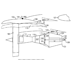
the compressor, has also increased. As a result of the increase in the bypass
ratio, negative
aerodynamic effects have been identified in the overall propulsion system that
includes the
nacelle and the engine. Accordingly, what is needed is an improved propulsion
system that
does not experience these negative aerodynamic effects.
SUMMARY
[0005] In a featured embodiment a propulsion system has a fan and a
gear. A
turbine is configured to drive the gear to drive the fan. The turbine has an
exit point. A
1
CA 2898207 2018-08-09
CA 02898207 2015-07-14
WO 2014/123796
PCMJS2014/014367
diameter (Di) is defined at the exit point. A nacelle surrounds a core engine
housing. The fan
is configured to deliver air into a bypass duct defined between the nacelle
and the core engine
housing. A core engine exhaust nozzle is downstream of the exit point. A
downstream most
point of the core engine exhaust nozzle is defined at a distance (Le or I)
from the exit point.
A ratio of the distance (Lc or Ln) to the diameter (Di) is greater than or
equal to about 0.90.
[0006] In another
embodiment according to the previous embodiment, the core
engine exhaust nozzle includes a plug. The downstream most point of the core
engine
exhaust nozzle is defined by a downstream end of the plug. The ratio is
greater than or equal
to about 1.06.
[0007] In another
embodiment according to any of the previous embodiments, the
ratio is greater than or equal to about 1.20.
[0008] In another
embodiment according to any of the previous embodiments, a
plug is received within the core engine exhaust nozzle. A downstream end of
the core engine
exhaust nozzle extends downstream of a downstream most end of the plug. The
distance (La)
is defined to a downstream most end of the core engine exhaust nozzle. The
ratio is greater
than or equal to about 1.02.
[0009] In another
embodiment according to any of the previous embodiments, the
ratio is greater than or equal to about 1.17.
[0010] In another
embodiment according to any of the previous embodiments, a
bypass ratio is greater than about 6.
[0011] In another
embodiment according to any of the previous embodiments, the
bypass ratio is greater than about 10.
[0012] In another
embodiment according to any of the previous embodiments, an
exhaust case is positioned between the turbine and the core engine exhaust
nozzle.
[0013] In another
featured embodiment, a propulsion system has a fan and a gear.
A turbine is configured to drive the gear to drive the fan. The turbine has an
exit point. A
diameter (Di) is defined at the exit point. A nacelle surrounds a core engine
housing. The fan
is configured to deliver air into a bypass duct defined between the nacelle
and the core engine
housing. A core engine exhaust nozzle is downstream of the exit point. The
core engine
exhaust nozzle has a plug. A downstream most point of the core engine nozzle
is defined by
a downstream end of the plug at a distance (Lc) from the exit point. A ratio
of the distance
(Lc) to the diameter (Dr) is greater than or equal to about 1.06.
2
CA 02898207 2015-07-14
WO 2014/123796
PCT/US2014/014367
[0014] In another
embodiment according to the previous embodiment, the ratio is
greater than or equal to about 1.20.
[0015] In another
embodiment according to any of the previous embodiments, an
exhaust case is positioned between the exit of the turbine and an entrance to
the engine
exhaust nozzle.
[0016] In another
embodiment according to any of the previous embodiments, a
bypass ratio is greater than about 6.
[0017] In another
embodiment according to any of the previous embodiments, the
bypass ratio is greater than about 10.
[0018] In another
featured embodiment, a propulsion system has a fan and a gear.
A turbine is configured to drive the gear to drive the fan. The turbine has an
exit point. A
diameter (DO is defined at the exit point. A nacelle surrounds a core engine
housing. The fan
is configured to deliver air into a bypass duct defined between the nacelle
and the core engine
housing. A core engine exhaust nozzle is downstream of the exit point. A
downstream most
point of the core engine exhaust nozzle is downstream of an internal plug
received within the
core engine exhaust nozzle. The downstream most point is defined at a distance
(4) from
the exit point. A ratio of the distance (La) to the diameter (Di) is greater
than or equal to
about 0.90.
[0019] In another
embodiment according to the previous embodiment, the ratio is
greater than or equal to about 1.02.
[0020] In another
embodiment according to any of the previous embodiments, the
ratio is greater than or equal to about 1.17.
[0021] In another
embodiment according to any of the previous embodiments, an
exhaust case is positioned between the exit of the turbine and an entrance to
the engine
exhaust nozzle.
[0022] In another
embodiment according to any of the previous embodiments, a
bypass ratio is greater than about 6.
[0023] In another
embodiment according to any of the previous embodiments, the
bypass ratio is greater than about 10.
[0024] In another
embodiment according to any of the previous embodiments, a
gear ratio of the gear is greater than or equal to about 2.3.
3
CA 02898207 2015-07-14
WO 2014/123796
PCT/US2014/014367
[0025] These and other features may be best understood from the
following
drawings and specification.
BRIEF DESCRIPTION OF THE DRAWINGS
[0026] Figure I schematically shows a gas turbine engine.
[0027] Figure 2 shows a first embodiment of an improved propulsion
system
according to the present invention.
[0028] Figure 3 shows a second embodiment of an improved propulsion
system
according to the present invention.
DETAILED DESCRIPTION
[0029] Figure 1 schematically illustrates a gas turbine engine 20. The
gas turbine
engine 20 of Figure 1 is a two-spool turbofan that generally incorporates a
fan section 22, a
compressor section 24, a combustor section 26 and a turbine section 28.
Alternative engines
might include an augmentor section (not shown) among other systems or
features. The fan
section 22 drives air along a bypass flow path B in a bypass duct defined
within a nacelle 15,
while the compressor section 24 drives air along a core flow path C for
compression and
communication into the combustor section 26 then expansion through the turbine
section 28.
Although depicted as a two-spool turbofan gas turbine engine in the disclosed
non-limiting
embodiment, it should be understood that the concepts described herein are not
limited to use
with two-spool turbofans as the teachings may be applied to other types of
turbine engines
including three-spool architectures.
[0030] The exemplary engine 20 generally includes a low speed spool 30
and a
high speed spool 32 mounted for rotation about an engine central longitudinal
axis A relative
to an engine static structure 36 via several bearing systems 38. It should be
understood that
various hearing systems 38 at various locations may alternatively or
additionally be provided,
and the location of bearing systems 31 may be varied as appropriate to the
application.
[0031] The low speed spool 30 generally includes an inner shaft 40 that
interconnects a fan 42, a low pressure compressor 44 and a low pressure
turbine 46. The
inner shaft 40 is connected to the fan 42 through a speed change mechanism,
which in the
exemplary gas turbine engine 20 is illustrated as a geared architecture 48 to
drive the fan 42
at a lower speed than the low speed spool 30. The high speed spool 32 includes
an outer
4
CA 02898207 2015-07-14
WO 2014/123796
PCT/US2014/014367
shaft 50 that interconnects a high pressure compressor 52 and high pressure
turbine 54. A
combustor 56 is arranged in the exemplary gas turbine 20 between the high
pressure
compressor 52 and the high pressure turbine 54. A mid-turbine frame 57 of the
engine static
structure 36 is arranged generally between the high pressure turbine 54 and
the low pressure
turbine 46. The mid-turbine frame 57 further supports bearing systems 38 in
the turbine
section 28. The inner shaft 40 and the outer shaft 50 are concentric and
rotate via bearing
systems 38 about the engine central longitudinal axis A which is collinear
with their
longitudinal axes.
[0032] The core
airflow is compressed by the low pressure compressor 44 then
the high pressure compressor 52, mixed and burned with fuel in the combustor
56, then
expanded over the high pressure turbine 54 and low pressure turbine 46. The
mid-turbine
frame 57 includes airfoils 59 which are in the core airflow path C. The
turbines 46, 54
rotationally drive the respective low speed spool 30 and high speed spool 32
in response to
the expansion. It will be appreciated that each of the positions of the fan
section 22,
compressor section 24, combustor section 26, turbine section 28, and fan drive
gear system
50 may be varied. For example, gear architecture 48 may be located aft of
combustor section
26 or even aft of turbine section 28, and fan section 22 may be positioned
forward or aft of
the location of gear system 48.
[0033] The engine
20 in one example is a high-bypass geared aircraft engine. In a
further example, the engine 20 bypass ratio is greater than about six (6:1),
with an example
embodiment being greater than about ten (10:1), the geared architecture 48 is
an epicyclic
gear train, such as a planetary gear system or other gear system, with a gear
reduction ratio of
greater than about 2.3 (2.3:1) and the low pressure turbine 46 has a pressure
ratio that is
greater than about five (5:1). In one disclosed embodiment, the engine 20
bypass ratio is
greater than about ten (10:1), the fan diameter is significantly larger than
that of the low
pressure compressor 44, and the low pressure turbine 46 has a pressure ratio
that is greater
than about five (5:1). Low pressure turbine 46 pressure ratio is pressure
measured prior to
inlet of low pressure turbine 46 as related to the pressure at the outlet of
the low pressure
turbine 46 prior to an exhaust nozzle. It should be understood, however, that
the above
parameters are only exemplary of one embodiment of a geared architecture
engine and that
the present invention is applicable to other gas turbine engines including
direct drive
turbofans.
CA 02898207 2015-07-14
WO 2014/123796
PCT/US2014/014367
[0034] A
significant amount of thrust is provided by the bypass flow B due to the
high bypass ratio. The fan section 22 of the engine 20 is designed for a
particular flight
condition -- typically cruise at about 0.8 Mach and about 35,000 feet. The
flight condition of
0.8 Mach and 35,000 ft, with the engine at its best fuel consumption - also
known as "bucket
cruise Thrust Specific Fuel Consumption (`TSFC ')" - is the industry standard
parameter of
lbm of fuel being burned divided by lbf of thrust the engine produces at that
minimum point.
"Low fan pressure ratio" is the pressure ratio across the fan blade alone,
without a Fan Exit
Guide Vane ("FEGV") system. The low fan pressure ratio as disclosed herein
according to
one non-limiting embodiment is less than about 1.45. "Low corrected fan tip
speed" is the
actual fan tip speed in ft/sec divided by an industry standard temperature
correction of [(Tram
R) / (518.7 R)[". The "Low corrected fan tip speed" as disclosed herein
according to one
non-limiting embodiment is less than about 1150 ft / second.
[0035] In high
bypass ratio engines, a nacelle 102 as shown in Figure 2 will have
a relatively great diameter. A fan 100 is shown within the nacelle 102,
somewhat
schematically. The fan is driven by a gear drive 112, and driven by a fan
drive turbine 146 in
a turbine section 116. Turbine section 116 may include a higher pressure
turbine 147
upstream of the fan drive turbine 146. A compressor 114 is also illustrated. A
diameter Dt is
defined as the diameter of the last blade airfoil stage 117 in the fan drive
turbine section 146.
[0036] A core
engine exhaust nozzle 122 has an inner periphery 124 which tapers
downwardly to define a nozzle at an end point 125. The angle at which the
nozzle tapers has
a maximum defined by balancing aerodynamic characteristics and core engine
exhaust nozzle
weight. As an example, the maximum angle may be approximately greater than
twelve
degrees or less than seventeen degrees, and preferably between fourteen and
sixteen degrees,
and most preferably at fifteen degrees, all measured relative to the
horizontal.
[0037] A plug 126
is shown to extend beyond an end point 125 of a housing of the
core engine exhaust nozzle 122. The plug has a downstream most end 128.
[0038] The use of a
gear drive 112 reduces the overall length of the turbine
section 116 as compared to conventional direct drive turbofan engines. As an
example, a
direct drive turbofan engine capable of producing a similar amount of thrust
as the engine
embodiment shown in Figure 2, may have its last turbine airfoil stage at the
point 120
(schematically shown). Further, such a conventional direct drive turbofan
engine typically
6
CA 02898207 2015-07-14
WO 2014/123796
PCT/US2014/014367
would have a nacelle 110 (schematically shown) with a much smaller diameter as
compared
to the nacelle 102 of the engine embodiment shown in Figure 2.
[0039] The nacelle
102 has a maximum diameter at point 104. To eliminate (or at
least reduce) negative aerodynamic effects, an outer surface 106 of the
nacelle 102, which is
downstream of the point 104, also has a limitation on a maximum inwardly
extending angle
to prevent separation of air, balancing aerodynamic characteristics and
nacelle weight.
Thus, in one embodiment, the maximum angle for the surface 106 may be on the
order of
about fourteen degrees, again measured relative to a horizontal axis. Of
course, in other
embodiments, the angle may he less than fourteen degrees.
[0040] An inner
surface 108 of the nacelle 102 forms a nozzle at its downstream
end 109 with an outer surface 111 of a core housing. In accordance with,
conventional gas
turbine design principles, manufacturers would typically try to reduce weight,
and thus
increase fuel efficiency. Under such conventional design strategy, one of
ordinary skill
would typically seek to minimize the length of the core engine exhaust nozzle
122 and any
exhaust case 118. That is, one might seek to minimize the length downstream of
the
downstream end 117 of the turbine section 116 illustrated in Figure 2.
However, Applicant
has discovered that given the maximum angle for the surface 124, this would
raise challenges
with regard to creating an effective nozzle at point 109. To overcome this
detriment, the
shown embodiment increases the length of the combined exhaust case 118 and
core engine
exhaust nozzle 122. While the core engine exhaust nozzle 122 is illustrated
starting at the
point 120 at which the last turbine airfoil stage of a non-geared engine would
be expected to
be, this is merely for illustration simplicity. The two points need not be
related. The same is
true with the illustration that point 120 coincides with the downstream end of
a exhaust case
118.
[0041] As a result,
whereas the overall length of the turbine section 116 of the
embodiment shown in Figure 2 is shorter than the corresponding length of the
turbine of a
non-geared counterpart engine, the overall length of the combined exhaust case
118 and
nozzle 122 of the embodiment shown in Figure 2 is longer than would be
expected.
[0042] To define
the length of the nozzle 122 and exhaust case 118 (if used), a
dimension Lc is defined from the point 117 to the point 128.
[0043] As an
example, in one engine, Dt was 27.6 in., and Le was 33.5 in. This
results in a ratio of about 1.21. In another engine example, where Dt was 33.5
in. and Lc was
7
CA 02898207 2015-07-14
WO 2014/123796
PCT/US2014/014367
43.7 in., the ratio was about 1.30. In a third engine example, where Dt was
35.9 in. and Lc
was 50.0 in., the ratio was about 1.39. In another proposed engine example,
where Dt was
53.6 in. and Lc was 88.0 in., the ratio was as high as about 1.64.
[0044] In general,
this disclosure extends to geared turbofan engines with a ratio
of Lc to D, of equal to or above about 1.06, and more narrowly equal to or
above about 1.20.
[0045] Figure 3
shows another embodiment, which is generally the same as the
Figure 2 embodiment, other than the plug 226 does not extend beyond the
downstream end
225 of a housing of the core engine exhaust nozzle 222. Again, in the shown
embodiment,
the inward movement of the surface 224 in the nozzle is limited to a maximum
angle of about
fifteen degrees measured relative to the horizontal, and thus an exhaust case
118 is also
utilized in this embodiment. A dimension Lõ is defined between the point 117
at the
downstream end of the fan drive turbine section 146 of the turbine section 116
and the point
225 at the downstream end of the nozzle 222.
[0046] In one such
engine example, where D, was 27.6 in. and Lõ was 28.2 in., the
ratio was about 1.02. In another engine example, where D, was 33.5 in. and Ln
was 34.6 in.,
the ratio was about 1.03. In another engine example, wherein D, was 35.9 in.
and Lõ was
38.8 in., the ratio was about 1.08. In another proposed engine, where D, was
53.6 in. and Ln
was 69.2 in., the ratio was about 1.29.
[0047] In general,
this disclosure extends to geared turbofan engines with a ratio
of Ln to D, equal to or above about 0.90, more narrowly above about 1.02, and
more
narrowly above about 1.17.
[0048] For purposes
of this application, the plug and housing are collectively part
of a core engine exhaust nozzle, such that points 128 and 225 are the
respective downstream
most points of the core engine exhaust nozzle.
[0049] The core
engine exhaust nozzle itself should have sufficient stiffness, and
should be formed of a material that would have appropriate strength
characteristics at
1,200 F. A material with a density of about .3 lbslin.3 may be utilized to
reduce the overall
weight. In one embodiment, the core engine exhaust nozzle 122/222 may be
formed of rolled
sheet stock, with a thickness less than 2.5 percent of a diameter of an inner
flow path of a
turbine. In another embodiment, the core nozzle may be formed of a sandwich
structure, or
may be formed to have a corrugated shape to reduce weight. In another
embodiment, the core
engine exhaust nozzle may be formed of ceramic matrix composites. Of course,
other
8
CA 02898207 2015-07-14
WO 2014/123796
PCT/US2014/014367
materials for the core exhaust nozzle are possible and are fully within the
scope of this
disclosure.
[0050] Although
various embodiments of this invention have been disclosed, a
worker of ordinary skill in this art would recognize that certain
modifications would come
within the scope of this invention. For that reason, the following claims
should be studied to
determine the true scope and content of this invention.
9