Note: Descriptions are shown in the official language in which they were submitted.
13~240
PNEUMATIC HYDRAULIC SIDE LIF$ING JACK
FIELD OF THE INVENTION
The invention relates to vehicle jacks
and vehicle repair equipment, and more particularly to
jack assemblies used in raising one side of a vehicle.
BACKGROUND PRIOR ART
An example of a prior art side lifting
jack is illustrated in the U.S. Gray et al. Patent
4,379,545, issued April 12, 1983. Attention i8 also
directed to the U.S. Nielsen Patent 3,252,590, i~sued
May 24, 1966; the U.S. Gray Patent 3,302,927, issued
February 7, 1967 and Australian Patent Specification
143,755.
Attention is also directed to British
Patent 1 556 608; Russian Publication 753785; Russian
Publication 753786; the U.S. Wooding Patent 4,127,255,
issued November 28, 1978; and the U.S. Feilbach et al.
Patent 3,268,208, issued August 23, 1966. Attention is
further directed to the U.S. Arnes Patent 3,014,698,
issued December 26, 1961; the U.S. Trautman et al.
Patent 2,730,903, issued January 17, 1956~ the U.S.
Forster Patent 2,588,509, issued March 11, 1952; the
U.S. Mandelko et al. Patent 2,494,099, issued
January 10, 1950; the U.S. Johnson Patent 2,400,235,
issued May 14, 1946; the U.S. Bentley Patent 867,549,
issued October 1, 1907; the U.S. Stark Patent 815,757,
issued March 20, 1906; Swiss Patent 405 664; and the
U.S. Jackson Patent 2,404,577, issued July 23, 1946.
,,:
130~240
--2--
SUMMARY OF THE INVENTION
The pre~ent invention provides an
improved side lifting jack having a pneumatically and
hydraulically actuated lifting cylinder for raising a
lift arm of the side lifting jack. The jack includes a
hydraulic fluid reservoir and means for supplying air
pressure to the hydraulic fluid reservoir to cause
hydraulic fluid to be delivered to the lift cylinder.
The lifting jack further includes a flow restricting
device to control flow of hydraulic fluid into or out
of the hydraulic cylinder and thereby prevent sudden
movement of the jack or sudden extension of the lift
cylinder assembly in the event that the load on the
lift jack is suddenly reduced or removed from the lift
jack. The jacX further includes a ratch and pawl
arrangement to selectively prevent retraction of the
piston of the hydraulic cylinder and lowering of the
vehicle in the event of failure of the hydraulic
cylinder.
More particularly, the invention
include~ a side lifting jack for lifting a vehicle and
including a lift arm having one end supported by at
least one wheel and the other end adapted to extend
under a vehicle, and jack means for supporting the
other end of the lift arm, the jack means including a
hydraulic cylinder and an extensible piston housed in
the hydraulic cylinder, and one of-the cylinder and the
piston being connected to the other end of the lift arm
for raising the other end of the lift arm in response
to extension of-the hydraulic cylinder. In one
embodiment of the invention the lift arm includes a
hydraulic fluid reservoir, and means are also provided
for connecting a source of air pressure to the-
hydraulic fluid reservoir. Means are also provided for
connecting the hydraulic fluid reservoir in the lift
~306240
--3--
arm to the hydraulic cylinder such that hydraulic fluid
can be supplied from the fluid reservoir to the
hydraulic cylinder when air pressure is applied to the
hydraulic fluid reservoir.
In a preferred embodiment of the
invention means are further provided for selectively
locking the piston in a selected extended position,
this locking means including a plurality of stop
members fixed to the piston and spaced apart along the
length of the piston, and a pawl supported by the
cylinder and selectively engageable with a selected one
of the stop members, the pawl being supported for
movement between an engaging position wherein the pawl
prevents retraction of the piston into the cylinder and
a pawl retracted position wherein the pawl is spaced
from the stop members, and the piston is freely movable
with respect to the cylinder.
In one embodiment of the invention the
hydraulic cylinder is supported by the piston for
vertical movement in response to extension of the
piston, and means are further provided for pivotally
joining the other end of the lift arm to the lower end
of the cylinder to permit relative pivotal movement of
the cylinder with respect to the lift arm as the
cylinder extends and retracts. This relative pivotal
movement eliminates side loading on the components of
the lifting jack and also permits the lifting jack
components to follow the arc of the side of the vehicle
during the lifting and retracting operations.
Various other features and advantages
of the invention will be apparent by reference to the
~ollowing description of a preferred embodiment, from
the drawings and from the claims.
1306240
--4--
BRIEF DESCRIPTION OF TNE DRAWINGS
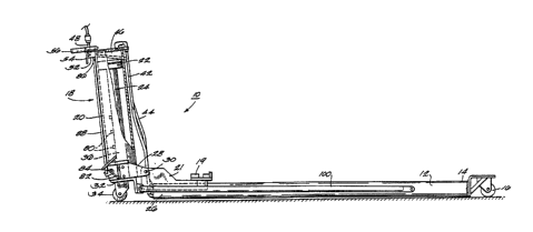
Fig. 1 i8 a side elevation view of a
side lift jack embodying the invention and with
portions broken away.
Fig. 2 is an elevation view of the side
lift jack illustrated in Fig. 1.
Fig. 3 is a view similar to Fig. 1 and
showing the side lift jack in elevated condition.
Fig. 4 is an enlarged partial end
elevation view of the side lift jack illustrated in
Figs. 1 through 3.
Fig. 5 is an enlarged partial view of a
portion of the side lift jack illustrated in Fig. 1.
Fig. 6 i5 a schematic view of the
hydraulic and pneumatic circuit of the side lift jack
shown in Figs. 1-5.
Before describing a preferred
embodiment of the invention in detail, it i5 to be
understood that the invention is not limited to the
details of construction and to the arrangement of the
components set forth in the following deqcription or
illustrated in the drawings. The invention is capable
of other embodiments and of being practiced and carried
out in various ways. Also, it is to be understood that
the phraseology and terminology employed herein is for
the purpose of description and should not be regarded
as limiting.
DESCRIPTION OF A PREFERRED EMBODIMENT
Illustrated in Fig. 1 is a side lifting
jack 10 embodying the invention and for use in lifting
one side of a vehicle (not shown) to permit repair or
maintenance work on the vehicle. The side lifting jack
includes a lift arm 12 having opposite ends, one end 14
1306240
--5--
being supported by a caster or wheel 16 and adapted to
extend under a vehicle. In a preferred form of the
invention, the lift arm 12 will have a length of at
least approximately two-thirds the width of the vehicle
to be lifted. The opposite end of the lift arm 12
includes a transversely extending vehicle support
member 19 adapted to be positioned beneath a side of a
vehicle or beneath a side portion of a vehicle frame to
engage the vehicle and for lifting the side of the
vehicle. The vehicle support member 19 is supported by
a pair of parallel, spaced apart, generally vertical
plates 21 projecting upwardly from the end of the lift
arm and fixed to the lift arm. While the saddle 19
could have other construction in the specific
arrangement illustrated in the drawings, the saddle 19
has a configuration adapted to house and retain the
pinch weld of an automobile.
The opposite end o the lift arm 12 is
~upported by a piston and cylinder assembly 18
including a generally vertically oriented cylinder 20
and piston 22 having a downwardly extending piston rod
24. In the illustrated arrangement, the hydraulic
cylinder 20 is supported by the downwardly extending
piston 22 for generally vertical movement, and the
cylinder 20 includes a lower end pivotally joined to
the opposite end 26 of the lift arm 12. More
particularly, a bracket 28 is fixed to the lower end of
the cylinder 20, and the vertical plates 21 fixed to
the end 26 of the lift arm 12 are connected to the
bracket 28 by a hinge pin or connecting pin 30.
The ~ide lifting jack 10 also includes
a base 32 which in the particular arrangement
illustrated in the drawings is comprised of an
elongated bar or angle having opposite ends supported
by spaced apart casters 34.
13062~Q
The piston rod 24 of the piston and
cylinder assembly 18 includes a lower end 36 fixed to
the bar 32 intermediate its opposite ends and such that
the lower end 36 of the piston rod 24 is supported by
the bar 32.
In a preferred form of the invention
the lift arm 12 comprises an elongated tank defining a
hydraulic fluid reservoir 40 of sufficient volume that
the tank can house sufficient hydraulic fluid to be
supplied to the hydraulic cylinder 20. In a preferred
form of the invention the fluid reservoir 40 is
operably connected to the upper end of the hydraulic
cylinder through hydraulic fluid line 42. Fluid line
42 comprises a supply line for delivering hydraulic
fluid from the reservoir 40 to a chamber 46 defined by
the upper end of the cylinder 20. Means are also
provided for supplying air under pressure to the
hydraul~c fluid reqervoir 40. In the illustrated
arrangement this means for supplying air to the
hydraulic fluid re~ervoir includes a coupling 48 and an
air hose 44 extending from the coupling 48 to the
hydraulic fluid re~ervoir. In one form of the
invention the coupling 48 can comprise a conventional
quick disconnect coupling for an air hose of the type
commonly included in auto repair facilities and service
areas.
In a preferred form of the invention,
the hydraulic fluid used in the side lifting jack of
the invention will be synthetic hydraulic fluid or oil
which will not mix with air in the system. One
hydraulic fluid which can be used is synthetic
hydraulic fluid manufactured by Ams/Oil, Inc.,
Superior, Wisconsin.
As illustrated in Fig. 1, means are
further provided for restricting the rate of flow of
hydraulic fluid between the reservoir 40 and the
'
:, ,
-` 130624C~
hydraulic cylinder 20. While in other embodiments,
other flow restricting means could be provided, in the
illustrated arrangement the flow restricting means
comprises and elongated tube 41 having a small diameter
interior bore, the elongated tube being housed in the
reservoir and having an open end 43. In the
illustrated arrangement the tube has a length of
approximately 58 inches and an internal bore diameter
of .493 inches. This arrangement is effective to limit
the flow of hydraulic fluid through the fluid line 42
and thereby limits the rate of flow of hydraulic fluid
from the reservoir 40 to the cylinder 20 and thereby
controlling the rate of vertical lift of the cylinder
20.
Also included is a manually operable
control valve 52 for controlling the air pressure
supplied by line 44 to the hydraulic fluid reservoir to
provide ~or rai~ing and lowering of the ~ide lifting
jack. In the illustrated arrangement, the manually
operable valve 52 i~ controlled by a control lever 54.
The control lever 54 and valve 52 are operable to
permit the operator to increase the air pressure in the
hydraulic fluid reservoir 40 thereby forcing hydraulic
fluid into the cylinder to raise cylinder 20 or venting
air pressure from the reservoir 40 permitting flow of
hydraulic fluid out of the cylinder to the reservoir
and lowering of the lift jack.
Means are also provided for selectively
mechanically supporting the cylinder 20 in a raised
position, this means including a plurality of
mechanical stops 80 fixed to the piston rod 24 and
spaced along its length. A pawl 82 is supported by the
lower end of the cylinder 20 and selectively engages a
selected one of the stops 80 when the piston 22 is
extended and the cylinder 20 is raised. The pawl 82 is
supported by a pivot pin 84 and pivots between a
- ~ 306240 `
disengaged position and a stop or engaging position. A
handle 86 is connected to the pawl by a connecting rod
88 and a bracket 90. In the illustrated arrangement
the pawl 82 is mounted eccentrically with respect to
the pivot pin 84, and the weight of the pawl 82, the
connecting rod 88 and handle 86 tend to bias the pawl
toward a stop engaging position.
During operation of the lift jack 10,
the pawl 82 and stop members 80 selectively prevent
downward movement of the cylinder 20 and lift arm 12.
Lowering of the lift jack requires the operator to grip
the handle 86 to disengage the pawl 82 and also actuate
the valve 52 to first raise the cylinder slightly to
permit disengagement with the pawl with the stop member
and then actuation of the valve to lower the lift arm.
The side lifting jack also includes a
pair of elongated braces 100, each of the braces 100
having one end pivotally connected to the inwardly
extending end 14 of the lift arm 12 and an opposite end
pivotally connected to an end of the base member 32 to
provide support between the inwardly extending end 14
of the lift arm 12 and the ends of the base 32.
, Various features of the invention are
set forth in the following claims.