Note: Descriptions are shown in the official language in which they were submitted.
CA 02327226 2000-i2-of Atty. Dkt. No.; 27438/118
VEHICLE INTERCHANGEABLE REPAIR SYSTEM
RELATED APPLICATIONS
This application claims the benefit of U.S. Provisional
Application No. 60/168, 521, filed D~cember 2, 1999.
~~ELD of THE ~NV~NTIOIu
The present invention relates to the vehicle repair field and
more particularly to a system for moving, positioning and manipulating a
vehicle and vehicle parts on an interchangeable repair system utilizing a
variety of devices coupled to the repair system.
'° BACKGROUND OF THE INVENTION
In the vehicle repair business, a damaged or in-need-of-repair
vehicle is usually brought to a vehicle body shop or the like for corrective
procedures. Vehicle bodies and frames come in different shapes and
sizes, from the smallest foreign made vehicles to pick-up trucks. To
as repair such vehicles, the vehicle repair facility must have available a
repair
system, usually called a "rack" or a "frame pulling" bench or an "in-floor,
system." During the repair procedure, there are a variety of tools that are
utilized by an operator to effect a proper repair of a vehicle. In addition to
the repair system rack or bench having a force applying device mounted
Zo thereon, an operator might also require a cutting device, or a welding
device or a winch or a measuring system, etc. Each of these individual
devices, are typically mounted on its own carriage or set of wheels or
some such other manipulating system that must be moved from one side
of the vehicle repair system to another side depending on the work
zs required. An operator must maneuver such devices from one position to
another position typically over the floor of the vehicle repair facility which
001.673383.2
CA 02327226 2000-i2-of Atty. Dkt. No.: X74381118
requires movement of other tools or apparatus which is inefficient and
time consuming.
Thus there is a need for a vehicle repair system that provides
for easy maneuvering of various tools and apparatus utilized during a
vehicle repair procedure. There is a further need for an interchangeable
repair system that allows for the interchangeability of tools and apparatus
mountable on a vehicle repair rack or bench that can be moved anywhere
around th$ circumference of the vehicle being repaired, i.e., have a 380
35 degree maneuver capability.
SUMMARY OF THE INVENTION
The present invention provides a vehicle interchangeable
repair system and a method for using the same in a vehicle repair facility.
The vehicle interchangeable repair system comprises a repair platform
4o having a carriage mounted thereon and configured to move along the
periphery of the repair platform, An accessory platftirrn is removably
coupled to the carriage and an interchangeable tool is removably mounted
on the accessory platform. The vehicle interchangeable repair system
allows an operator to modify the vehicle repair system to accommodate
as the type of vehicle and type of vehicle repair that has to bs affected on
such vehicle. The vehicle repair system can receive interchangeable tools
as selected by an operator of the system. The carriage is configured to
move along the periphery of the repair platform a full 380 degrees to a
position as selected by th~a operator. Additional carriages can be mounted
so on the repair platform and support the same type of interchangeable tool
or different interchangeable tools as selected and determined by the
operator.
The present invention also provides the method for repairing
a vehicle with a vehicle interchangeable repair system. The method
5s comprises the steps of securing a vehicle to a repair platform of the
001.679383.2 -3-
- CA 02327226 2000-i2-of Atty. Dkt. No.: 2743$1118
vehicle interchangeable repair system and selecting an interchangeable
tool to perform a procedure on the vehicle. The method also includes
mounting the interchangeable tool on an accessory platform and coupling
the accessory platform to a carriage mounted on the repair platform. The
so operator moves the carriage along the periphery of the repair platform to a
selected position, locks the carriage in the selected position and uses the
interchangeable tool on the vehicle to affect a repair procedure. A repair
procedure can include the moving, positioning, manipulating, removing
and measuring the vehicle and vehicle parts. The method can also include
Bs the steps of selecting a second interchangeable tool and mounting the
second interchangeable tool into a second carriage. The operator can
then use the second tool on the vehicle during the repair procedure. A
third and additional tool can be mounted on additional carriages or
interchanging a third tool for either the first or second tool and using the
~o third tool on the vehicle.
The present invention also provides a vehicle interchangeable
repair system comprising a means for supporting and securing the vehicle,
a means for carrying mounted on the means for supporting and configured
to move along the periphery of the means for supporting, a means for
7s accessorizing, removably coupled to the means for carrying and an
interchangeable tool removably mounted on the means fdr accessorizing.
The vehicle interchangeable repair system can also include a means for
locking to fix the position of the means for carrying on the means for
supporting. The means for carrying can also be provided with a means
eo for positioning to fix the position of the means for accessorizing. The
vehicle interchangeable repair system can al$o include at least one
additional means for carrying mounted on the means for supporting with
an additional means for aacessorizing having another interchangeable tool
removably mounted thereon removably coupled to such additional means
es for carrying,
OQ1.6733A3.2 -4-
CA 02327226 2000- 12-O1 Atty. UKt. IHO.: L /4~tf17 'I ti
BRIEF DESCRIPTION OF THE DRAWINGS
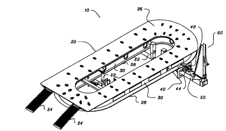
Fig. 1 is a prospective view illustrating a vehicle
interchangeable repair system (rack type) having a carriage coupled to the
s periphery of the repair rack and having an interchangeable tool, of the pull
tower type, mounted on an accessory platform coupled to the carriage.
Fig. 2 is a prospective view illustrating the vehicle
interchangeable repair system with two embodiments of an
interchangeable tool mounted respectively on an accessory platform
yo which are coupled to two carriages mountable to the repair platform.
Fig. 3 is a prospective view illustrating a variety of
interchangeabl~ tools that are mountable on ar~ accessory platform which
engages a carriage of the present vehicle interchangeable repair system.
DETAILED DESCRIPTION OF THE PREFERRED EMBODIMENTS
~s Referring to Fig. 1, there is illustrated a vehicle
interchangeable repair system (10). It's principal parts include a repair
platform (20), a carriage (40) mounted on the perimeter of the repair
platform for maneuvering along said perimeter, an accessory platform (50)
removably coupled to the carriage (40) and an interchangeable tool (60)
2o mounted an the accessory platform (50). The present vehicle
interchangeable repair system (10) is structured to allow an operator to
customize or build a specific vehicle repair system especially far a .
particular procedure on a specitic vehicle. The present vehicle
interchangeable repair system (10) receives different devices that can be
z6 interchangeably connected into the carriage (40) attached to the work
repair platform (20) and structur~d to maneuver completely around the
repair platform (20) circumference. In other words, when a vehicle is
secured to the work surface (26) of the repair platform (20) the carriage
oot _er3sas.z -5-
CA 02327226 2000-12-O1 Hlty. uKl. IVV.: tl'f,?QI ~ m
(401 supporting the accessory platform (50) and an interchangeable tool
30 (fi0) can be maneuvered entirely around the vehicle and be positioned in
the most advantageous and convenient location around the repair
platform (20) as determined by the operator.
The repair platform (20) is provided with one or more leg
sets (22) for adjusting the height of the repair platform (20) above the
as floor surface of the vehicle repair facility. The leg set (22) can be a
fixed
height assembly, or a variable height assembly utilizing hydraulic or
pneumatic cylinders to raise or Power the repair platform (20) as
determined by the operator. Ramps (24) are removably attached to the
repair platform (20) to facilitate the movement of the vehicle on and off
4o the repair platform (20). The ramps (24) can be placed on one end or the
other end of the repair platform (20) or they can be placed on both ends
of the repair platform (20) to provide a drive-through capability to the
vehicle interchangeable repair system 1101. The repair platform (20) is
also provided with a bottom plate (28) and an intermediate web (30)
as which provides the structural integrity of the repair platform (20).
Typically, the hydraulic or pneumatic plumbing fnot shown) is routed in
the interior space formed by the work surface (26), the bottom plate (28)
and the intermediate web i30) of the repair platform (20). A plurality of
openings are provided in the intermediate web (30) to allow access to the
6o plumbing and such other procedur~s as are deemed necessary by the
operator of the system. The work surface (26) of the repair platform (20)
can be provided with a plurality of openings to facilitate the procedures
utilized to service a vehicle placed on the repair platform (20).
Referring now to digs. 1 and 2, the vehicle interchangeable
ss repair system (10) is provided with at least one carriage i4~) which is
coupled to the repair platform (20). The carriage (40) is provided with
traverse rollers (42) which engage the bottom plate t2$) of the repair
platform (201 to facilitate the movement of the carriage (40) around the
001.873383.2 -6-
ca o232~226 2ooo-i2-of Atty. Dkt. No.: ~/4~ts1~1 ~It3
circumference of the repair platform (20) and thereby having a 360
av degree maneuverability capability. The carriage (40) is also provided with
a carriage lock (44) and a carriage lock pin (46) which is used to set and
lock the position of the carriage (40) at a given location around the
periphery of the repair platform (20) as determined by an operator. The
carriage (40) is also provided with a lateral position assembly (48) which
8s facilitates the side to side positioning of the accessory platform (50) as
will be described below. It should be understood that the carriage (40)
can be coupled to the repair platform (20) in any convenient and
conventional manner such as rails that are attached to the work surface
(26) or the bottom plate (2$) of the repair platform (20).
~o The interchangeability feature of the present vehicle
intgrchang~aable repair system (7 0) is the accessory platform (50) which is
coupled and locked to the carriage (40). The accessory platform (501 i$
provided with a hole at one end which receives a pivot pin (52) mountable
in the carriage (40), A pivot lock (54) manipulated by a pivot lock handle
~s (56) is provided on the accessory platform (50) with the pivot lock (54)
engaging the lateral position assembly (413) of the carriage (40) to position
the accessory platform (50) in a side to side orientation within the
carriage (40) is determined by the operator. The accessory platform (50)
pivots about the pivot pin (52) which allows the positioning of the
eo accessory platform (50) and the interchangeable tool (60) mounted
thereon as determined by the operator. The accessory platform (50) can
be of any convenient length and cross-section, however the preferred
embodiment is a square cross-section hollow tube. The hollow tube
facilitates and receives the hydraulic and pneumatic plumbing and
e5 electrical wiring to accommodate the interchangeable tools (60) mounted
on the platform.
Fig. 2 illustrates two embodiments of the interchangeable
tool (60) that is mounted on the accessory platform (50). One
Op1.673393.2 7
' CA 02327226 2000-i2-of Atty. Dkt. No.: 2743$/'118
embodiment is a pull tower (6$) and the other embodiment is a tube type
so pull tower (fib) both of which are force applying devices utilized in a
vehicle repair procedure. It should be understood that tha interchangeable
tool (60) can be of the same type mounted in a separate carriage (40)
during the repair procedure or they may be of different types (as
illustrated in Fig, 2) during a repair procedure.
as Fig. 3 illustrates a variety of interchangeable tools (60) that
can be mounted on the accessory platform 150) and coupled to the
carriage (40) of the present vehicle interchangeable repair system (10).
The type of tools illustrated are a crane (621, a dent pullet (fi4), a pull
tower (66), a tube type pull tower (6$), a measuring system (70), a part
holding assembly (72), a doorlbumper holding assembly (74), a pushlpull
assembly (76), a winch (7$), a welder (80), a plasma cutter ($2), a
vacuum recovery system (84), a video system (86), and a tool (88).
The measuring system (70) can be any coordinate
determining system. For example, the measuring system (70) can be
mechanical, such as a tram gauge, or an electro-mechanical system. The
measuring system (~0) can utilize lasers, or audio waves, or use any
device that can transmit and/or receive electro-magnetic energy. The
measuring system can also utilize an optical-camera system, such as a
combination of light emitting diodes and charge-coupled devices. The
> >o welder (80) can be any suitable welding system, such as a shielded metal-
arc, gas metal-arc (MIG), gas tungsten-arc, or axyacetylen~e system. It is
contemplated by the present vehicle interchangeable repair system (10)
that any one of such interchangeable tools (60) can be mount~rd on an
accessory platform (501 and coupled to the carriage (40) mounted on the
~ ~ s repair platform (20). It is also contemplated that two or more carriages
(40) can be mounted on the repair platform (20) with the same or
alternative interchangeable tools (60) mounted in the respective carriages
(40) as determined by an operator to perform the given procedure in the
001.673383.2 -a-
ca o232~226 2ooo-i2-of Atty. Dkt. No.: Z74;~~i177ti
most efficient and convenient manner, It is contemplated that any type
~zo of tool X88) that can be mounted on the accessory platform (50) can be
utilized in the present vehicle interchangeable repair system (t0).
Thus, there is provided a vehicle interchangeable repair
system for us~ in a vehicle repair facility. While several embodiments of
the present invention have been disclosed in detail herein, various
~z6 modifications may be made. For example, the carriage may be mounted
on a mobile platform that is anchored to a Boor of a repair facility utilizing
an in-floor track system or anchor pots. By way of further modification,
the interchangeable tool may be mounted on the accessory platform such
that the interchangeable tool can be pivoted independently of the lateral
~aa movement of the accessory platform within the carriage. Such
modifications and variations in use are intended to fall within the scope of
the appended claims.
oo~.smea.z -9'